EP0617218B1 - Leitungsanschluss, insbesondere für mindestens eine Kapillarrohr-Leitung - Google Patents
Leitungsanschluss, insbesondere für mindestens eine Kapillarrohr-Leitung Download PDFInfo
- Publication number
- EP0617218B1 EP0617218B1 EP94103461A EP94103461A EP0617218B1 EP 0617218 B1 EP0617218 B1 EP 0617218B1 EP 94103461 A EP94103461 A EP 94103461A EP 94103461 A EP94103461 A EP 94103461A EP 0617218 B1 EP0617218 B1 EP 0617218B1
- Authority
- EP
- European Patent Office
- Prior art keywords
- terminal
- flange
- sections
- conduit
- section
- Prior art date
- Legal status (The legal status is an assumption and is not a legal conclusion. Google has not performed a legal analysis and makes no representation as to the accuracy of the status listed.)
- Expired - Lifetime
Links
Images
Classifications
-
- F—MECHANICAL ENGINEERING; LIGHTING; HEATING; WEAPONS; BLASTING
- F16—ENGINEERING ELEMENTS AND UNITS; GENERAL MEASURES FOR PRODUCING AND MAINTAINING EFFECTIVE FUNCTIONING OF MACHINES OR INSTALLATIONS; THERMAL INSULATION IN GENERAL
- F16L—PIPES; JOINTS OR FITTINGS FOR PIPES; SUPPORTS FOR PIPES, CABLES OR PROTECTIVE TUBING; MEANS FOR THERMAL INSULATION IN GENERAL
- F16L5/00—Devices for use where pipes, cables or protective tubing pass through walls or partitions
- F16L5/02—Sealing
- F16L5/14—Sealing for double-walled or multi-channel pipes
Definitions
- the invention relates to a line connection according to the Preamble of claim 1.
- a line connection according to the Preamble of claim 1.
- Such lines can signal lines, supply lines, Alignment lines and similar connecting lines be, with at least one to all lines appropriately in essential not to the electrical line or to the line provided by energy waves but such lines are which are essentially spaced within the outer circumference of the actual line, the medium to be conducted record like that e.g. is the case with pipelines.
- the line connection is preferred for very fine lines with an outside width of less than 50, 20, 10 or even 5 mm provided, which can also be at most 2 or 1 mm, their wall thickness is less than 1 mm or of the order of magnitude of a few tenths of a millimeter.
- Such line connections are also in temperature sensor arrangements provided that according to EP-A-0 578 096 a hydraulic closed expansion system with two end units, namely form a temperature sensor and an actuator, which can move flexibly and / or elastically against each other only connected to one another via at least one of the lines are so that a signal picked up by an end unit over the trunk to one from the other end unit influenced control unit, e.g. one manually on different Temperature-adjustable operating controls, can be forwarded.
- a hydraulic closed expansion system with two end units namely form a temperature sensor and an actuator, which can move flexibly and / or elastically against each other only connected to one another via at least one of the lines are so that a signal picked up by an end unit over the trunk to one from the other end unit influenced control unit, e.g. one manually on different Temperature-adjustable operating controls, can be forwarded.
- Connecting lines e.g. to separate end units to connect to a common end unit or to only provide connections required for the manufacture, which are then closed as blind connections after manufacture are.
- E.g. is in a fluid system in addition to the functional or.
- Signal line expediently a filling connection, via which the system is filled or adjusted and then pressure-tight to the outside can be locked.
- the invention has for its object a line connection of the type mentioned, with which disadvantages known training or the type described avoided are and especially with compact training and high Connection quality ensures simplified production.
- connection opening is required in the area of the base body essentially centric symmetrical or circular or can be cylindrical.
- the connecting flange and / or connecting section as a line branching off from another line or two connection sections lying approximately coaxially one inside the other to provide, there are expediently at least two connection sections closely adjacent to each other, being in separate Intervene in connection openings that are separated into a axially adjoining common or enlarged connection opening pass over.
- the lines can be in one Connection flange associated longitudinal area through intermediate elements be completely separate and in at least a subsequent longitudinal area with a gap distance face each other freely and without further intermediate limitation. From this longitudinal section, the connecting sections project freely.
- connection sections expediently essentially separate, sleeve-like and dimensionally stable receptacles are provided, but they are useful instead of one piece as separate components with each other and / or with the base body or as a solid Unit are formed and from the body instead of in opposite directions essentially only in one project freely in one direction.
- connection section opposite the connection opening with a securing member, e.g. an adhesive, secured
- a securing member e.g. an adhesive
- the adhesive can thereby in this and / or in all other areas essentially only in capillary-fine Micro gaps can be provided in a very small amount.
- the respective Connection section an internal mold for shaping the connecting means, in particular the connecting flange or the securing member, so that this is not a separate one Tool is needed, but only on the outside of the counter-tools attacking the rigidly rigid connection flange are required, which the connection flange around the respective connection section around or between adjacent Form the connection sections.
- This will then between the connection sections a dimensionally stable and compacted in the structure Intermediate or spacer created that the Connects web-like connecting sections and opposite the Jacket sections of the respective connection sleeve about double Has thickness because it is two-ply.
- an approximately centric-symmetrical one or cylindrical sleeve section at least over part of its length due to only minor Parts of its outer circumference attacking, radially inwards directed pressure under plastic cold deformation along about axial surface lines deformed or crushed and thereby possibly in almost radial play or frictional connection with the associated connection section brought.
- An adhesive can already be in the form a thin layer, e.g. a paste, like a solder paste on Have been attached to the inner circumference of the connecting flange, so that there is a very fine, film-like and even distribution this plastic adhesive, which afterwards, e.g. through previous warming, solidified and completely closed or pressure-tight sealing not only in the area the outer circumference of the respective connection section, but also forms between adjacent connection sections.
- a line and a bracket wear the line at a distance from the associated end of the Connecting flange supports and e.g. sticking out freely. This results in a very small transverse distance between Line and bracket so that the line is already immediate following the connection flange due to the very close location to the Keep well shielded or protected from damage is.
- the bracket in one piece with the connecting flange training, it can also be done by a separate component, namely e.g. by one opposite the supported line thicker rod.
- connection flange is a fuse for one only outside the main body or the main body wear non-penetrating component, e.g. a position securing, centering, shielding, sealing or the like, which over the tight or sealed End of the connecting flange protrudes and / or opposite
- This safety link can also connected to the connecting flange as a separate component, e.g. by plugging on the outer circumference and / or by plugging in between the layers of the spacer on the inner circumference of the connecting flange.
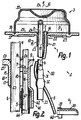
- the line connection 1 is on a closed assembly or Assembly 2 provided the two head-like units 3, 4, which has a single, in contrast essential slimmer capillary tube 5 connected together and also to a substantially slimmer filling line 6 are connected, the filling ends of which are freely accessible at the Outside of the unit 3 is, but from the filling process is kept tightly closed.
- Unit 3 forms one housing or button-shaped temperature sensor, which consists of only is composed of two one-piece components and to which the respective line 5 or 6 with an essentially straight line Connection section 7 or 8 is connected so that it opens or projects freely into the interior of the housing, the Connection is made through line connection 1.
- a base plate 9 in the form of an annular plate, which is at least partially sleeve-shaped Connection flange 10 carries in one piece.
- a central axis 11 this connecting flange 10 coincides approximately with the central axis of the base body 9 or the unit 3 together, while the two axes 12, 13 of the connecting sections 7, 8 on both sides are adjacent to the axis 11, namely the axis 12 of the Connection section 7 at a greater distance than that other axis 13, so that the axis 11 approximately in a generatrix of the connecting section 8 is located or its outer circumference in contrast, protrudes slightly to the axis 12.
- the components 9, 10 consist of a material that under such pressures or temperatures that can be formed during operation occur so that the components under all operating conditions are essentially dimensionally stable.
- the flange jacket 15 also forms a sleeve 16, 17th intermediate or connecting connecting sections 7, 8 Spacer 18, which is made in that the Flange jacket 15 to form axial notches 19 on the Outside is shaped inward over its entire thickness. All axes 11 to 13 are approximately like the spacer 18 in a common axial plane 20, in which the two each other opposite jacket parts of the spacer 18th essentially almost all over one another apply, and in each case continuously up to the outer circumference of the respective connection section 7 or 8. This is the Inner area of the flange jacket 15 in the area of the sleeves 16, 17 and the spacer 18 of cavities essentially completely free and the gap between the adjacent curved or flat surfaces are with an intimate filled with solder.
- Each of the components mentioned expediently consists of one metallic material, e.g. Steel, like stainless steel.
- the the sleeves 16, 17 forming longitudinal section 21 of the connecting flange 10 extends like these sleeves to the associated one outer end 23 or the end face formed thereby, the over the circumference of the respective sleeve 16, 17 approximately in one Level or perpendicular to the respective axis 11 to 13 can.
- the axes 11 to 13 can also not be parallel to each other or lie in separate axial planes.
- the flange jacket 15 is essentially only about the outer end face 25 of the base body 9 by an amount that about its largest, to be measured parallel to the axial plane 20 External width corresponds.
- the longitudinal section 21 and the sleeves 16, 17 lie in one Distance from the outer end face 25, however, can be opposite half of the total length of the connecting flange 10 or be longer than the subsequent longitudinal section 22.
- This longitudinal section 22 adjoining the base body 9 has an essentially cylindrical outer or inner circumference, its outer or inner width corresponding to that largest width of the longitudinal section 21 is approximately the same.
- the connection to the longitudinal section 22 approximately in the plane of the end face 25 can lie so that the constant cross sections of the longitudinal section 22 are provided on a length that is only about corresponds to the plate thickness of the base body 9.
- the outer circumferences of the two connection sections 7, 8 are in a gap distance from each other, which is of the order of magnitude the outer diameter or the radius of the connecting section 7 and / or two to four times the thickness of the Flange jacket 15 may lie, so that there is a distance in the Order of magnitude of 1 mm or less.
- the width of the bottom surfaces of the notches 19 can be in the
- the magnitude of the thickness of the flange jacket 15 are in turn in the order of the wall thickness of the connecting section 7 or less than the wall thickness of the connecting section 8 can be.
- the longitudinal section is formed by the described design 21 of the flange jacket 15 approximately on both sides of the axial plane 20 two double-shell sections each with two over an axially connected half shells, which in the area of outside of the connection sections 7 facing away from one another, 8 merge into one piece and between the connection sections 7, 8 abutting one another via an adhesive, such as a Solder means are interconnected.
- an adhesive such as a Solder means
- Depending on the requirements can also be glued, welded or a frictional press connection may be provided. It is also conceivable for at least one of the lines, in particular the line 6 in one piece with the connecting flange 10 form, so that this with an over the end surface 23rd protruding connection forms the filling opening.
- the narrowest, through the bottom surfaces of the notches 19 formed constriction region has a thickness that smaller than the outer width of the thinnest connection section 7 is.
- the directly to the outer circumference of the longitudinal section 22 connects and about compared to its wall thickness has the same minimum width.
- On their from the connecting flange 10 distal side is the recess 27 from one protruding from the end face 25, possibly annular Flank limited by the inner circumference an arcuate or annular rib 28 is formed, of its outer circumference approximately evenly about the axis 11 distributed ribs 29 go outward in a star shape.
- a bracket 30 is provided which the line 5th at an axial distance from the end 23 of the connecting flange 10 secure.
- the line 6 In about 30 to 70 times, in particular 50 to 60 times the outside width of line 5 Distance from the base body 9 is the line 6 with a closed in one piece with the closure 31 formed thereby, that your pipe jacket about a 5 to 10 times its longitudinal section corresponding to its outer width is flattened out that it is spaced between the ends this longitudinal section by spot welding widened flat head 32 with convex curved outer edges forms the approximately straight longitudinal edges of the flattened Pass over the longitudinal section.
- This longitudinal section extends to the free end 33 of line 6.
- the line 5 is with at least one, two, three or more steep turns the between the closure 31 or the head 32 and the Flange 10 lying longitudinal section of the approximately straight rod-shaped line 6 relatively tight wound, the winding pitch about the 5 to 30 times or 10 to 20 times the outer width of the Line 5 or the corresponding half of the outside width of the Line 6 can correspond.
- Outside the bracket 30 am free longitudinal section of the line 6 attacking tensile forces lead to an elastic narrowing of the turns 34 and / or to stop the last turn 34 on the through the extended outer edges of the head 32 formed shoulders, so that it is a very effective form-fitting but elastic compliant and self-reinforcing train protection for the Line 5 and therefore also for line connection 1 results.
- the unit 3 only has here apart from the base body 9 a one-piece cap 35 which with the cap edge 36 of her Coat in one within the outer circumference in the end face 26 provided annular groove 37 and by a of the types of attachment mentioned is attached sealed.
- the wall thickness of the cap 35 is smaller than that of the base body 9, its connection to the base body 9 radially far outside the outer circumference of the connecting flange 10 can lie.
- the unit 4 forms a membrane box or Actuator, the gap-like narrow membrane chamber 38 via a Connection nipple 40 to the associated end of line 5 is connected and sealed pressure-tight to the outside Space of the printing system belongs.
- the diaphragm box has a control cam on the opposite end 39 on which the axial curvature movements of the associated Front wall via a resilient switching arm or the like or on a switching device, such as a snap switch, transmits.
- the connecting flange 10 has a otherwise end surface lying essentially in a transverse plane 23 protruding fuse 41, which over the Protects sleeve 16 protruding area of line 5, shields, centered, secures against kinking or the like and / or corresponding functions for a further component 24, e.g. a flexible and flexible network electrically insulating protective tube 44 takes on the the line 5 is pushed on and from the line connection 1 to enough to connect to the unit 4 so that it is opposite the line 5 against positive displacement essentially is secured.
- the fuse 41 has one the end 23 protruding projection or arm 42 which e.g.
- the line connection 1 is according to the invention first e.g. in the manner of a coinage from a plate-shaped Blank for the basic body by producing the Breakthrough of the ribs, grooves or the like of the flange jacket 15 pulled out to its initial state. Then the two connection sections 7, 8 from the outside in the inserted through cylindrical flange jacket, whereby A radial securing of the position is not absolutely necessary. With two opposite and against each other The profile jacket then becomes movable profile stamping tools to form the constriction or notches 19 of the spacer 18 deformed.
- connection sections 7, 8 pressed apart and under pressure against the areas of the inside facing away from each other Flange jacket pressed because its in the area of the constriction opposite circumferential areas in cross section form oblique flanks like funnels. At the same time the inner circumference of the flange jacket is close to the outer circumference the connection sections 7, 8 created.
- solder paste then becomes liquid by heating in the soldering furnace or made creepable and then solidifies by cooling, so that there is a completely pressure-tight line connection.
- line 5 can also be connected to unit 4 are connected, after which all cavities of the printing system complete with thermal expansion active hydraulic fluid are filled and fluid expansions in the dimensionally stable Unit 3 for membrane deformations of unit 4 to lead.
Landscapes
- Engineering & Computer Science (AREA)
- General Engineering & Computer Science (AREA)
- Mechanical Engineering (AREA)
- Non-Disconnectible Joints And Screw-Threaded Joints (AREA)
- Quick-Acting Or Multi-Walled Pipe Joints (AREA)
- Endoscopes (AREA)
- Measuring Temperature Or Quantity Of Heat (AREA)
- Fire-Detection Mechanisms (AREA)
- Measuring Fluid Pressure (AREA)
Description
- Figur 1
- eine mit einem erfindungsgemäßen Leitungsanschluß versehene Baugruppe, teilweise im Schnitt.
- Figur 2
- einen Ausschnitt der Figur 1 in wesentlich vergrößerter und abgewandelter Ausbildung und
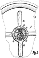
- Figur 3
- einen Ausschnitt der Figur 1 in geschnittener Ansicht von unten.
Claims (15)
- Leitungsanschluß mit einer Leitungsanordnung (5, 6), die mindestens einen Anschlußabschnitt (7) einer Kapillarrohr-Leitung (5), insbesondere eines im wesentlichen geschlossenen Drucksystems, und einen weiteren Anschlußabschnitt (8) aufweist sowie mit wenigstens einem Grundkörper (9), der in einer gemeinsamen Anschlußzone mindestens einen Anschlußflansch (10) mit einem Flanschmantel (15) und einem von diesem begrenzten Durchbruch (14) durch den Grundkörper (9) bildet, wobei an dem Flanschmantel (15) die Anschlußabschnitte (7, 8) befestigt sind, dadurch gekennzeichnet, daß zwischen den Anschlußabschnitten (7, 8) der Leitungsanordnung (5, 6) ein Zwischenglied (18) vorgesehen ist.
- Leitungsanschluß nach Anspruch 1, dadurch gekennzeichnet, daß der Anschlußflansch (10) gesonderte Anschlußöffnungen für wenigstens zwei Anschlußabschnitte (7, 8) der Leitungsanordnung (5, 6) bildet, zwischen den Anschlußöffnungen das Zwischenglied (18) vorgesehen ist und dieses Zwischenglied (18) zwei nahezu aneinander liegende Zwischengliedflächen aufweist, daß insbesondere der Flanschmantel im wesentlichen konstante Manteldicke aufweist, mindestens einen der Anschlußabschnitte (7, 8) am Außenumfang umfaßt und unter Bildung des Zwischengliedes (18) im Querschnitt einteilig über die Anschlußabschnitte (7, 8) im wesentlichen geschlossen durchgeht und daß vorzugsweise die Anschlußabschnitte (7, 8) im Abstand voneinander bzw. parallel zueinander liegen.
- Leitungsanschluß nach Anspruch 1 oder 2, dadurch gekennzeichnet, daß mindestens ein bis alle Anschlußabschnitte (7, 8) in einem Vormontage-Zustand über eine in wenigstens einer Richtung im wesentlichen radialspielfreie Zentrierverbindung in den Anschlußflansch (10) eingreifen, daß insbesondere mindestens ein Anschlußabschnitt (7, 8) mit einem Sicherungs- bzw. Dichtungsmaterial axial gegenüber dem Anschlußflansch (10) gesichert ist und daß vorzugsweise zwischen benachbarten Anschlußabschnitten (7, 8) eine Verbindung aus einem Sicherungs-bzw. Dichtmaterial vorgesehen ist.
- Leitungsanschluß nach einem der vorhergehenden Ansprüche, dadurch gekennzeichnet, daß mindestens ein Anschlußabschnitt (7, 8) haftend mit dem Anschlußflansch (10) verbunden ist, daß insbesondere wenigstens ein Anschlußabschnitt (7, 8) über einen vom Anschlußflansch (10) bzw. vom Anschlußabschnitt (7, 8) gesonderten Haftstoff befestigt ist und daß vorzugsweise mindestens ein Anschlußabschnitt (7, 8) über eine erstarrte Schmelzverbindung mit einem Anschlußflansch verbunden ist.
- Leitungsanschluß nach einem der vorhergehenden Ansprüche, dadurch gekennzeichnet, daß benachbarte Anschlußabschnitte (7, 8) einen lichten Abstand voneinander haben, der etwa in der Größenordnung der inneren Weite eines Anschlußabschnittes (7), der Wandungsdicke eines Anschlußabschnittes (8) und/oder des doppelten einer Wandungsdicke des Anschlußflansches (10) liegt, daß insbesondere benachbarte Anschlußabschnitte (7, 8) im Querschnitt jeweils auf Teilumfängen von wenigstens einem Schellenabschnitt umfaßt sind, der für zwei Anschlußabschnitte (7, 8) im Abstand zueinander liegende Schalenabschnitte bildet bzw. zwischen zwei Anschlußabschnitte (7, 8) eingreift und daß vorzugsweise zwei einander gegenüberliegende Schellenabschnitte im Querschnitt im Bereich des Zwischengliedes (18) sowie einer zwischen ihnen liegenden Ebene (20) geteilt sind und einteilig ineinander übergehen.
- Leitungsanschluß nach einem der vorhergehenden Ansprüche, dadurch gekennzeichnet, daß im Querschnitt ein zwischen benachbarten Anschlußabschnitten (7, 8) im Bereich des Zwischengliedes (18) liegender Raumbereich im wesentlichen lückenfrei mit einem Feststoff ausgefüllt ist, daß insbesondere das vom Anschlußabschnitt (7, 8) gesonderte Zwischenglied (18) 2- bis 3-schichtig ist und daß vorzugsweise einander gegenüberliegende Mantelabschnitte des Anschlußflansches (10) zwischen den benachbarten Anschlußabschnitten (7, 8) im wesentlichen ganzflächig annähernd aneinander anliegen bzw. unmittelbar aneinander befestigt sind.
- Leitungsanschluß nach einem der vorhergehenden Ansprüche, dadurch gekennzeichnet, daß der Anschlußflansch (10) zwischen benachbarten Anschlußabschnitten (7, 8) eine Kerbe (19) mit einer minimalen Kerbenweite bildet, die kleiner als die Wandungsdicke eines der Anschlußabschnitte (7, 8) bzw. des Anschlußflansches (10) ist, daß insbesondere der gegenseitige Bodenabstand zweier einander gegenüberliegender Kerben (19) kleiner als die Außenweite eines der Anschlußabschnitte (7) ist und daß vorzugsweise das Materialgefüge des Anschlußflansches (10) zwischen den benachbarten Anschlußabschnitten (7, 8) gegenüber im Abstand davon liegenden Bereichen verdichet ist.
- Leitungsanschluß nach einem der vorhergehenden Ansprüche, dadurch gekennzeichnet, daß der Anschlußflansch (10) Längsabschnitte (21, 22) unterschiedlicher Querschnitte aufweist, daß insbesondere unterschiedliche Längsabschnitte (21, 22) des Anschlußflansches (10) stetig gekrümmt ineinander übergehen und die Zwischengliedflächen im Übergangsbereich divergieren und daß vorzugsweise ein an den Grundkörper (9) anschließender Längsabschnitt (22) des Anschlußflansches (10) im wesentlichen zentrisch-symmetrische Querschnitte aufweist.
- Leitungsanschluß nach einer der vorhergehenden Ansprüche, dadurch gekennzeichnet, daß ein im wesentlichen zentrisch symmetrischer bzw. erweiterter Ausgangsquerschnitt des Anschlußflansches (10) eine lichte Weite hat, die der Summe der Außenweiten der zugehörigen Anschlußabschnitte (7, 8) zuzüglich deren Zwischenabstand entspricht, daß insbesondere ein Ende (24) des Anschlußflansches (10) im Querschnitt im wesentlichen zylindrisch und ein davon abgekehrtes Ende (23) im wesentlichen brillenförmig ist und daß vorzugsweise der Anschlußflansch (10) eine gegenüber dem doppelten einer Außenweite eines der Anschlußabschnitte (8) bzw. gegenüber seiner größten Außenweite etwa gleich große Länge hat.
- Leitungsanschluß nach einem der vorhergehenden Ansprüche, dadurch gekennzeichnet, daß der Anschlußflansch (10) Anschlußabschnitte (7, 8) unterschiedlicher Außen- bzw. Innenweite aufnimmt, daß insbesondere die Innenweite eines der Anschlußabschnitte (8) etwa der Außenweite eines weiteren Anschlußabschnittes (7) bzw. die Außenweite eines der Anschlußabschnitte (8) etwa dem doppelten der Außenweite eines weiteren Anschlußabschnittes (7) entspricht und daß vorzugsweise einer der Anschlußabschnitte (7) durch das Ende der eine Fernleitung bildenden Kapillarrohr-Leitung (5) bzw. einer der Anschlußabschnitte (8) durch das Ende einer frei vorstehenden Füllrohr-Leitung (6) gebildet ist, die außerhalb des Anschlußflansches (10) mit einem Verschluß (31) versehen ist.
- Leitungsanschluß nach einem der vorhergehenden Ansprüche, dadurch gekennzeichnet, daß mindestens einer der Anschlußabschnitte (7, 8) eine innere Prägeform für den Anschlußflansch (10) bildet, daß insbesondere der Anschlußflansch (10) asymmetrisch um die Anschlußabschnitte (7, 8) gebogen ist und daß vorzugsweise der Anschlußflansch (10) aus einer im wesentlichen nur in Mantellinienberührung mit dem jeweiligen Anschlußabschnitt (7, 8) stehenden Vormontage-Lage im wesentlichen durch Kraftangriff radial benachbart zum Anschlußabschnitt (7, 8) um diesen verformt ist.
- Leitungsanschluß nach einem der vorhergehenden Ansprüche, dadurch gekennzeichnet, daß der Anschlußflansch (10) an eine quer zu mindestens einer Flanschachse (11 bis 13) liegende Wandung (9) anschließt, daß insbesondere der Anschlußflansch (10) wenigstens teilweise einteilig mit der plattenförmigen Wandung (9) ausgebildet ist und daß vorzugsweise der Anschlußflansch (10) eine gegenüber der Wandung (9) kleinere Wandungsdicke aufweist bzw. an einer Wandungs-Stirnseite (25) von einer unmittelbar entlang seines Außenumfanges anschließenden Vertiefung (27) bzw. von einer Ringrippe (28) umgeben ist.
- Leitungsanschluß nach einem der vorhergehenden Ansprüche, dadurch gekennzeichnet, daß der Grundkörper (9) mindestens eine im Abstand vom Anschlußflansch (10) liegende Halterung (30) für wenigstens eine Leitung der Leitungsanordnung (5, 6) trägt, daß insbesondere die Halterung (30) vom Anschlußflansch (10) stabförmig nach außen vorstehend ausgeht und daß vorzugsweise eine Leitung (5) im Abstand vom Anschlußflansch (10) durch steilwendelförmige Umwicklung oder dergleichen gegenüber einer weiteren Leitung (6) festgelegt ist bzw. mindestens ein Anschlußabschnitt (7, 8) über beide Enden (23, 24) des Anschlußflansches (10) vorsteht.
- Leitungsanschluß nach einem der vorhergehenden Ansprüche, dadurch gekennzeichnet, daß der Grundkörper (9) mindestens eine Sicherung (41) für wenigstens einen von den Anschlußabschnitten (7, 8) gesonderten Bauteil (44) bzw. für eine freiliegende Leitung (5) trägt, daß insbesondere eine Sicherung (41) eine Abschirmung für ein Ende eines auf die Leitung (5) aufgeschobenen Schutzgliedes (44) bildet und daß vorzugsweise an eine äußere Endfläche (23) des Anschlußflansches (10) ein frei vorstehendes Sicherungsglied einteilig anschließt, dessen Innenfläche wenigstens teilweise im Abstand vom Außenumfang mindestens einer zugehörigen Leitung (5) liegt bzw. eine Steckaufnahme für das als Schutzmantel ausgebildete Schutzglied (44) trägt.
- Leitungsanschluß nach einem der vorhergehenden Ansprüche, dadurch gekennzeichnet, daß der Grundkörper (9) mindestens eine Wandung einer Druckdose oder dergleichen bildet, daß insbesondere die Wandung für mindestens zwei Leitungseingänge nur mit dem einen Durchbruch (14) versehen sowie ringförmig und durchgehend einteilig ausgebildet ist und daß vorzugsweise mit dem Grundkörper (9) ein Stellglied des geschlossenen Drucksystemes im wesentlichen ausschließlich über mindestens eine Leitung (5) verbunden ist.
Priority Applications (1)
| Application Number | Priority Date | Filing Date | Title |
|---|---|---|---|
| SI9430313T SI0617218T1 (en) | 1993-03-23 | 1994-03-08 | Pipe connection, in particular for at least one capillary tube |
Applications Claiming Priority (2)
| Application Number | Priority Date | Filing Date | Title |
|---|---|---|---|
| DE4309238A DE4309238A1 (de) | 1993-03-23 | 1993-03-23 | Leitungsanschluß, insbesondere für mindestens eine Kapillarrohr-Leitung |
| DE4309238 | 1993-03-23 |
Publications (3)
| Publication Number | Publication Date |
|---|---|
| EP0617218A2 EP0617218A2 (de) | 1994-09-28 |
| EP0617218A3 EP0617218A3 (de) | 1995-02-15 |
| EP0617218B1 true EP0617218B1 (de) | 2000-05-24 |
Family
ID=6483514
Family Applications (1)
| Application Number | Title | Priority Date | Filing Date |
|---|---|---|---|
| EP94103461A Expired - Lifetime EP0617218B1 (de) | 1993-03-23 | 1994-03-08 | Leitungsanschluss, insbesondere für mindestens eine Kapillarrohr-Leitung |
Country Status (5)
| Country | Link |
|---|---|
| EP (1) | EP0617218B1 (de) |
| AT (1) | ATE193363T1 (de) |
| DE (2) | DE4309238A1 (de) |
| ES (1) | ES2148250T3 (de) |
| SI (1) | SI0617218T1 (de) |
Families Citing this family (1)
| Publication number | Priority date | Publication date | Assignee | Title |
|---|---|---|---|---|
| DE102013200279A1 (de) | 2013-01-10 | 2014-07-10 | E.G.O. Elektro-Gerätebau GmbH | Verfahren zum Betrieb eines Backofens und Backofen |
Family Cites Families (4)
| Publication number | Priority date | Publication date | Assignee | Title |
|---|---|---|---|---|
| US3654965A (en) * | 1967-06-23 | 1972-04-11 | Pneumatiques Caoutchouc Mfg | Closure members for pipe sections |
| US4181330A (en) * | 1977-03-22 | 1980-01-01 | Noriatsu Kojima | Horn shaped multi-inlet pipe fitting |
| SU1651008A1 (ru) * | 1989-11-24 | 1991-05-23 | Организация П/Я Х-5498 | Узел герметизации проходки пучка трубопроводов |
| DE4005978A1 (de) * | 1990-02-26 | 1991-08-29 | Porsche Ag | Leitungsdurchfuehrung fuer durch eine tragwand hindurchzufuehrende leitungen, insbesondere schlauch- und/oder rohrleitungen |
-
1993
- 1993-03-23 DE DE4309238A patent/DE4309238A1/de not_active Withdrawn
-
1994
- 1994-03-08 SI SI9430313T patent/SI0617218T1/xx unknown
- 1994-03-08 EP EP94103461A patent/EP0617218B1/de not_active Expired - Lifetime
- 1994-03-08 DE DE59409369T patent/DE59409369D1/de not_active Expired - Fee Related
- 1994-03-08 ES ES94103461T patent/ES2148250T3/es not_active Expired - Lifetime
- 1994-03-08 AT AT94103461T patent/ATE193363T1/de not_active IP Right Cessation
Also Published As
| Publication number | Publication date |
|---|---|
| ATE193363T1 (de) | 2000-06-15 |
| EP0617218A3 (de) | 1995-02-15 |
| DE4309238A1 (de) | 1994-09-29 |
| SI0617218T1 (en) | 2000-08-31 |
| ES2148250T3 (es) | 2000-10-16 |
| DE59409369D1 (de) | 2000-06-29 |
| EP0617218A2 (de) | 1994-09-28 |
Similar Documents
| Publication | Publication Date | Title |
|---|---|---|
| EP1171731B1 (de) | Fitting oder armatur zur herstellung einer pressverbindung mit einem eingesteckten rohrende | |
| EP1333219B1 (de) | Schnellverschlusskupplung | |
| DE2724793C2 (de) | ||
| DE2802937A1 (de) | Anordnung zur schubsicherung fuer eine muffenrohrverbindung | |
| DE3009436A1 (de) | Fluid-verbindungsstueck | |
| EP0902226A1 (de) | Verbindung eines Metallrohres mit einer Metallhülse | |
| DE69606602T2 (de) | Gesockelte elektrische lampe | |
| DE69002026T2 (de) | Biegsame nichtmetallische Verbindung. | |
| EP0214395B1 (de) | Elastische Rohrverbindung, insbesondere flexible Rohrkupplung | |
| DE3533318A1 (de) | Entloetgeraet und damit verwendbare entloetspitze | |
| EP0759120B1 (de) | Abgaskrümmer für einen mehrzylindermotor | |
| DE102012109740A1 (de) | Elektrische Heizvorrichtung und Verfahren zur Herstellung einer solchen elektrischen Heizvorrichtung | |
| DE19606003A1 (de) | Schiebesitz-Rohrverbindung | |
| EP3951228B1 (de) | Schlauchbaugruppe | |
| DE102012214480A1 (de) | Wärmetauscheranordnung | |
| EP2511685A1 (de) | Messzelle mit einem Gehäuse zur Aufnahme eines Sensors, insbesondere eines Druckmessumformers | |
| EP0202481A2 (de) | Endpartie eines Metallschlauches | |
| DE1912905B2 (de) | Korrosionsbeständiger Kegelhahn | |
| EP0529419B1 (de) | Kapillarrohr-Leitungssystem sowie Verfahren zur Herstellung eines Kapillarrohr-Leitungssystem | |
| DE19816692A1 (de) | Brennkammerdichtungsanordnung mit hohem Rückstellungsvermögen | |
| EP1265019B1 (de) | Stützrohr und Verbindungsanordnung | |
| WO2000014443A1 (de) | Rohrverbindung zum gasdichten anschluss an ein mehrschichtverbundrohr | |
| DE4309238A1 (de) | Leitungsanschluß, insbesondere für mindestens eine Kapillarrohr-Leitung | |
| DE19516830A1 (de) | Preßwerkzeuge und Verfahren zum Verbinden von rohrförmigen Elementen | |
| EP0461308B1 (de) | Übergangsstück zum Verbinden von Kunststoffrohren mit Armaturen aus metallischen Werkstoffen, insbesondere im Sanitär- und Heizungsbereich |
Legal Events
| Date | Code | Title | Description |
|---|---|---|---|
| PUAI | Public reference made under article 153(3) epc to a published international application that has entered the european phase |
Free format text: ORIGINAL CODE: 0009012 |
|
| AK | Designated contracting states |
Kind code of ref document: A2 Designated state(s): AT DE ES FR GB IT |
|
| RAX | Requested extension states of the european patent have changed |
Free format text: SI PAYMENT 940308 |
|
| PUAL | Search report despatched |
Free format text: ORIGINAL CODE: 0009013 |
|
| AK | Designated contracting states |
Kind code of ref document: A3 Designated state(s): AT DE ES FR GB IT |
|
| RHK1 | Main classification (correction) |
Ipc: F16L 5/14 |
|
| 17P | Request for examination filed |
Effective date: 19950413 |
|
| 17Q | First examination report despatched |
Effective date: 19960327 |
|
| GRAG | Despatch of communication of intention to grant |
Free format text: ORIGINAL CODE: EPIDOS AGRA |
|
| GRAG | Despatch of communication of intention to grant |
Free format text: ORIGINAL CODE: EPIDOS AGRA |
|
| GRAH | Despatch of communication of intention to grant a patent |
Free format text: ORIGINAL CODE: EPIDOS IGRA |
|
| GRAH | Despatch of communication of intention to grant a patent |
Free format text: ORIGINAL CODE: EPIDOS IGRA |
|
| GRAA | (expected) grant |
Free format text: ORIGINAL CODE: 0009210 |
|
| AK | Designated contracting states |
Kind code of ref document: B1 Designated state(s): AT DE ES FR GB IT |
|
| AX | Request for extension of the european patent |
Free format text: SI PAYMENT 19940308 |
|
| REF | Corresponds to: |
Ref document number: 193363 Country of ref document: AT Date of ref document: 20000615 Kind code of ref document: T |
|
| REF | Corresponds to: |
Ref document number: 59409369 Country of ref document: DE Date of ref document: 20000629 |
|
| ET | Fr: translation filed | ||
| GBT | Gb: translation of ep patent filed (gb section 77(6)(a)/1977) |
Effective date: 20000704 |
|
| ITF | It: translation for a ep patent filed | ||
| REG | Reference to a national code |
Ref country code: ES Ref legal event code: FG2A Ref document number: 2148250 Country of ref document: ES Kind code of ref document: T3 |
|
| PG25 | Lapsed in a contracting state [announced via postgrant information from national office to epo] |
Ref country code: GB Free format text: LAPSE BECAUSE OF NON-PAYMENT OF DUE FEES Effective date: 20010308 Ref country code: AT Free format text: LAPSE BECAUSE OF NON-PAYMENT OF DUE FEES Effective date: 20010308 |
|
| PG25 | Lapsed in a contracting state [announced via postgrant information from national office to epo] |
Ref country code: ES Free format text: LAPSE BECAUSE OF NON-PAYMENT OF DUE FEES Effective date: 20010309 |
|
| PLBE | No opposition filed within time limit |
Free format text: ORIGINAL CODE: 0009261 |
|
| STAA | Information on the status of an ep patent application or granted ep patent |
Free format text: STATUS: NO OPPOSITION FILED WITHIN TIME LIMIT |
|
| 26N | No opposition filed | ||
| GBPC | Gb: european patent ceased through non-payment of renewal fee |
Effective date: 20010308 |
|
| PG25 | Lapsed in a contracting state [announced via postgrant information from national office to epo] |
Ref country code: FR Free format text: LAPSE BECAUSE OF NON-PAYMENT OF DUE FEES Effective date: 20011130 |
|
| REG | Reference to a national code |
Ref country code: FR Ref legal event code: ST |
|
| PG25 | Lapsed in a contracting state [announced via postgrant information from national office to epo] |
Ref country code: DE Free format text: LAPSE BECAUSE OF NON-PAYMENT OF DUE FEES Effective date: 20020101 |
|
| REG | Reference to a national code |
Ref country code: ES Ref legal event code: FD2A Effective date: 20030303 |
|
| PG25 | Lapsed in a contracting state [announced via postgrant information from national office to epo] |
Ref country code: IT Free format text: LAPSE BECAUSE OF NON-PAYMENT OF DUE FEES;WARNING: LAPSES OF ITALIAN PATENTS WITH EFFECTIVE DATE BEFORE 2007 MAY HAVE OCCURRED AT ANY TIME BEFORE 2007. THE CORRECT EFFECTIVE DATE MAY BE DIFFERENT FROM THE ONE RECORDED. Effective date: 20050308 |