EP0616227A1 - Digital directional resonance magnetometer - Google Patents
Digital directional resonance magnetometer Download PDFInfo
- Publication number
- EP0616227A1 EP0616227A1 EP94400546A EP94400546A EP0616227A1 EP 0616227 A1 EP0616227 A1 EP 0616227A1 EP 94400546 A EP94400546 A EP 94400546A EP 94400546 A EP94400546 A EP 94400546A EP 0616227 A1 EP0616227 A1 EP 0616227A1
- Authority
- EP
- European Patent Office
- Prior art keywords
- field
- digital
- resonance
- value
- converter
- Prior art date
- Legal status (The legal status is an assumption and is not a legal conclusion. Google has not performed a legal analysis and makes no representation as to the accuracy of the status listed.)
- Withdrawn
Links
Images


Classifications
-
- G—PHYSICS
- G01—MEASURING; TESTING
- G01R—MEASURING ELECTRIC VARIABLES; MEASURING MAGNETIC VARIABLES
- G01R33/00—Arrangements or instruments for measuring magnetic variables
- G01R33/20—Arrangements or instruments for measuring magnetic variables involving magnetic resonance
- G01R33/24—Arrangements or instruments for measuring magnetic variables involving magnetic resonance for measuring direction or magnitude of magnetic fields or magnetic flux
Definitions
- the present invention relates to a directional magnetometer with digital resonance type. It finds an application in the measurement of weak magnetic fields, for example of a few tens of microteslas.
- the invention finds applications in geophysics, in mineral prospecting, in spatial detection, etc.
- the magnetometer of the invention is of the directional resonance type. These devices are well known and described, for example, in French patent application FR-A-2 663 751 filed by the present Applicant (this application itself containing Bibliographical references on the subject), or in the corresponding European application EP-A-463 919, or in the article by D. DURET, M. MOUSSAVI and M. BERANGER entitled “Use of High Performance Electron Spin Resonance Materials for the Design of Scalar and Vectorial Magnetometers", published in the journal IEEE Transactions on Magnetics, vol. 27, n ° 6, Nov. 1991, pp. 5405-5407.
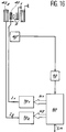
- FIG. 1 first of all, we see a sample 2 containing a material having electronic or nuclear spins; a first winding 3 creating a polarizing magnetic field noted Hb and directed in a direction D; a second winding 4 near the sample 2; a current generator 5 of adjustable intensity supplying the first winding 3; a high-frequency generator 6 connected to a measurement bridge 8, which in turn is connected to a resonant circuit 10 containing the winding 4; a low noise amplifier 16 connected to the measurement bridge 8; a balanced mixer 18 receiving, on the one hand, the voltage delivered by the amplifier 16, and, on the other hand, a reference voltage emanating from the high-frequency generator 6; and, finally, a low-pass filter 20.
- Sample 2 is subjected to the field to be measured, ie Hm, as well as to the polarization field Hb. These two fields are not generally collinear.
- the magnetic field measured by such a device is, in fact, the sum of Hb and the component of Hm projected on direction D, component denoted (Hm) D , taking into account the fact that Hb is much larger than Hm
- Hm the component of Hm projected on direction D
- the generator 6, connected to the circuit 10 and to its winding 4, is able to excite the resonance of the spins of the sample 2. Its frequency is fixed with very high precision (10 ⁇ 9 to 10 ⁇ 6). Spin resonance occurs when the frequency fo of the excitation signal is equal to the LARMOR frequency, conventionally determined by the relation (1 / (2 ⁇ )) ⁇ Ho, where ⁇ is the gyromagnetic ratio specific to the sample used (in the case of the electron ⁇ 2 ⁇ .28 GHz / T) and Ho is the value at resonance of the total magnetic field applied.
- the circuit 10 and its winding 4 are, at the same time, capable of detecting this resonance, the circuit 8 having the function of decoupling the excitation and the detection.
- FIG. 1 detects the passage through resonance when, the frequency fo being fixed, the total field H passes through the value Ho.
- FIG. 3 thus shows the variations of the voltage V1 delivered by the low-pass filter 20 when the field H varies and passes through Ho.
- This curve is of the dispersion type, that is to say antisymmetrical, with a positive part, a cancellation (for the value Ho corresponding to the resonance) and a negative part.
- the knowledge of Ho makes it possible to go back to (Hm) D if one knows Hb.
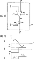
- the device of FIG. 4 is a variant in which an oscillator 22 and a winding 24 are also used to generate a magnetic field having an audio frequency denoted fm, this field, called “stirring field”, superimposed on the field of polarization Hb.
- the low-pass filter 20 of FIG. 1 is replaced by a band-pass filter 26 centered around the frequency fm.
- a phase shifter 28 receives the high frequency signal from the generator 6 and supplies the balanced mixer 18 with an appropriate phase signal.
- a circuit 30 for synchronous detection at the frequency fm receives on one of its inputs a reference signal from the generator 22.
- This reference signal has a frequency fm but its amplitude and its phase can be made different from that of the signal supplied by the oscillator 22 to the coil 24.
- the circuit 30 has another input connected to the output of the filter 26 and it finally delivers a voltage Vs.
- Linearity can be improved by a field feedback, obtained by using the voltage V1 (figure 3) or the voltage Vs (figure 5) as an error signal, by integrating this voltage and injecting, into a feedback coil, current proportional to the integrated voltage.
- the axis of this feedback coil must also be parallel to the direction D of the polarization field.
- the modulus of the vector sum (cf. fig. 2) is substantially equal to the sum of the field created by the bias current and directed in the direction D and of the projection onto this direction of the external field to be measured.
- the means 31 and 32 control the device to resonance, whatever the field applied from the outside.
- the integrator 31 can either directly deliver the feedback current, or deliver a voltage, in which case it must be associated with a voltage-current converter, in the form for example of a resistance.
- known directional resonance magnetometers generally comprise a sample with spins subjected to the field to be measured, means for applying to this sample a field magnetic polarization, means for applying a radiofrequency field to the sample and exciting the resonance of the spins, means for detecting this resonance, means for generating an asymmetric electrical signal which is canceled out when the total field applied to the sample takes the value Ho corresponding to the resonance of the spins and which is positive or negative depending on whether the total field applied is larger or smaller than this particular value (Ho). If there is no field to measure, the device is set to be at resonance. In the presence of a field to be measured, the feedback field restores the resonance and the value of the integrated error signal (or of the feedback current) constitutes the measurement of the magnetic field.
- these magnetometers Although satisfactory in certain respects, these magnetometers nevertheless have drawbacks. In particular, they are of analog character, so that if one wants to have a measurement in digital, it is necessary to associate an analog-digital converter to them.
- the precision of these converters is adapted to the very high precision required for certain magnetometers. Indeed, when it comes to measuring, for example, the Earth's magnetic field, the value of which is around 50 microteslas, the error tolerated is 10 picoteslas. This therefore requires a resolution of 0.2 per thousand. Such precision corresponds to a 22-bit analog-digital converter, which does not exist in the current state of the art.
- the object of the present invention is precisely to remedy this drawback. To this end, it offers a magnetometer which intrinsically comprises digital means such that the signal delivered by the device is not only already digital, but corresponds to an accuracy adapted to the high performance of the device.
- a field Ho defined by 2 ⁇ fo / ⁇ is applied to the sample. .
- This can be achieved by any suitable means.
- a field to be measured is applied to the sample, the resonance disappears.
- a feedback current must be established from the error signal obtained.
- this function is fulfilled by logical and digital means.
- a digital error signal is generated as a multi-digit number. From this number, a feedback current is formed which, applied to one of the conventionally provided windings, makes it possible to restore the resonance.
- the passage through resonance is detected by a logical organ which blocks the number at its corresponding value, this then being the translation of the field to be measured. We thus obtain directly the value of the magnetic field in digital.
- the polarization field Ho is created either by polarization means (in this case it is superimposed on the feedback field when it exists), or by feedback means which then generate a field corresponding to the sum of Ho and the field feedback.
- FIG. 7 is a general diagram of a magnetometer according to the invention.
- the means already used in the prior art are symbolized by a block referenced 40. It must be understood that these are the means already described with reference to FIGS. 1, 4 and 6, taken alone or in combination, and which allow d excite the resonance, detect it and supply a signal V canceling out when the total magnetic field takes the value Ho corresponding to the resonance.
- the magnetometer of the invention is characterized by a logic circuit 50, which receives the signal in question and delivers a logic signal S which can take two logic states EL1, EL2, the second indicating that the signal V has been canceled, this is that is, we have moved on to resonance.
- the magnetometer of the invention also comprises a processor (or controller) 60, which receives the logic signal S and delivers a digital signal N, in other words a number with several bits (for example 8 or 16 bits or more).
- This processor 60 also delivers, on a measurement output denoted SM, a number which has the stored value finally taken by the number N when the resonance has taken place.
- the magnetometer of the invention also comprises a digital-analog converter 70, which receives the number N and transforms it into current I (either directly or via a voltage, itself then converted into current).
- Current I feeds a winding 42 arranged near the sample 2.
- this winding 42 can be either a specific winding, added to the other windings conventionally existing in a magnetometer (as they have been represented in the figure 6 under references 3 and 24), or any one of these windings since it involves creating a feedback field to be directed in the general direction D common to all these windings.
- the bias current is adjusted so that we are at resonance. Then, the voltage V is zero and the logic signal S delivered by the circuit 50 is in its second logic state EL2.
- the processor 60 delivers a number N zero. No feedback current I is applied to the winding 42.
- the voltage V is no longer zero but takes a value which constitutes an error signal.
- the logic signal S goes into its first logic state EL1.
- the processor 60 increments the number N (positive or negative) by an appropriate algorithm, so that a current is applied to the winding 42. This results in a feedback field which modifies the total field applied to sample 2 until the projection of Hm onto direction D is exactly compensated for by the feedback field.
- the voltage V returns to zero, the logic signal S resumes its second logic state EL2 indicating to the processor 60 that the resonance has been restored.
- the processor blocks the number N at the value taken Nm and delivers this value Nm on the measurement output SM. This value Nm is the digital value of the projection of the field Hm to be measured on the direction D.
- the measured field corresponding to the final value Nm is equal to Nmbo +, where is an error term less than bo.
- the means of ensuring resonance by adjusting the polarization field are not shown explicitly and are assumed to be contained in the general means 40 which therefore contains the current source making it possible to create this polarization field via the winding 3.
- the reference current source 5 which makes it possible to create this field via the winding 42 is explicitly represented (the general means lacking this source is then referenced 40 ′).
- the reference current Iref is set to a value Io.
- the current I1 delivered by the converter 70 is added to this current, and this in an adder 76 which delivers the sum Io + I1, which is applied to the winding 42.
- FIG. 9 shows the variations of some signals appearing in the devices of FIGS. 7 and 8.
- the reference current Iref delivered by the source 5 is plotted on the abscissa and the logic signal S is on the ordinate. If, in the absence of a field to be measured, the current Iref is less than the value Io corresponding to the resonance, the signal S is in its first logic state EL1. If the current Iref crosses the value Io, the signal S switches and takes its second logic state EL2.
- the current I1 (part b) delivered by the converter 70 is zero.
- a current I1 equal to -Im is required to obtain resonance again, that is to say to switch the logic signal S from state EL1 to state EL2 (part c ).
- FIG. 8 is simple but it is dependent on the stability of the source 5.
- the accuracy of the measurement depends on the value of bo and of the capacity of the converter 70, which must correspond to the maximum value of the field Hm. An error can be introduced during the variation of bo.
- the means for forming the polarization field and those for the feedback field are separated: the first are constituted by the source 5 located in the general means 40 and the winding referenced 3 , while the second are constituted by the converter 70 and the specific winding 42.
- the digital means fulfill not only the measurement function but also that of prior calibration.
- the processor delivers a number N of value No corresponding to the resonance.
- the applied field is then Nobo + ⁇ (where ⁇ is still an error term increased by bo).
- the processor restores the resonance by forming a number Nm different from No and able to create a value feedback field (Nm-No) bo which will oppose the component of the field to be measured in direction D.
- the numerical value of the field will be given by (Nm-No). It is this which appears on the measurement output SM of processor 60.
- the error made is then less than 2bo.
- FIGS. 12 and 13 illustrate successive step and successive approximation algorithms respectively and FIG. 14 a step algorithm successive and two numbers.
- the field H incremented step by step with an amplitude bo, which corresponds to the least significant bit of the number N.
- This number N thus increases by a unit for each sampling, which is defined by a clock contained in the processor.
- the logic signal S delivered by the logic circuit 50 and shown in part (b) of FIG. 12 remains in its first logic state EL1, in this case the low state.
- the signal S switches to its second logic state EL2, in this case the high state, and the processor blocks the incrementation of the number N.
- the stop is holds for a duration D to allow the memorization of the number obtained.
- the number N is then reset to zero, which switches the logic circuit 50 back to state EL1 and the increment resumes.
- FIG. 13 is diagrammed an algorithm by successive approximations, which makes it possible to obtain the desired value more quickly.
- Figure 14 shows how we search for the two numbers N+m and N ⁇ m by successive approximations, first for the positive number N+, then for the negative number N ⁇ (part (a)) .
- Part (b) of the figure shows the shape of the logic signal S and the periods D+ and D ⁇ of memorization of the positive and negative numbers obtained.
- FIGS. 15 and 16 where the two converters bear the references 701 and 702. They respectively deliver currents I1 and I2.
- the difference between the two illustrated embodiments is that, in the first case (fig.15), the two currents I1 and I2 are added to each other in an adder 75, the sum resultant being applied to a single winding 42 whereas, in the second case (fig. 16), each current I1, I2 feeds a specific winding 421, 422 respectively.
- Hm (No. + -N1 - ) (No. + + N2 + + N3 - + N2 - -2) -2 (N2 + -N2 ⁇ ) (No. + + N1 - ) (No. + + N2 + + N+3 - + N2 - -2) -2 (N2 + + N2 - ) Ho using an average of (2) and (4) to minimize the error on the relationship between bo1 and bo2.
- FIG. 18 shows a possible embodiment of this circuit. It is a circuit comprising a comparator-inverter 80 supplied with ⁇ 5 volts and such that its output voltage is equal to -5 V when its input voltage is weakly positive and equal to + 5 V when its voltage input is weakly negative. This comparator is followed by a diode 82 charged by a resistor 84, the assembly making it possible to retain only the positive value of the output voltage of the comparator.
Abstract
Description
La présente invention a pour objet un magnétomètre directionnel à résonance de type numérique. Elle trouve une application dans la mesure des champs magnétiques faibles, par exemple de quelques dizaines de microteslas.The present invention relates to a directional magnetometer with digital resonance type. It finds an application in the measurement of weak magnetic fields, for example of a few tens of microteslas.
L'invention trouve des applications en géophysique, en prospection minière, en détection spatiale, etc...The invention finds applications in geophysics, in mineral prospecting, in spatial detection, etc.
Le magnétomètre de l'invention est du type directionnel à résonance. Ces appareils sont bien connus et décrits, par exemple, dans la demande de brevet français FR-A-2 663 751 déposée par le présent Demandeur (cette demande contenant elle-même des références bibliographiques sur le sujet), ou dans la demande européenne correspondante EP-A-463 919, ou encore dans l'article de D. DURET, M. MOUSSAVI et M. BERANGER intitulé "Use of High Performance Electron Spin Resonance Materials for the Design of Scalar and Vectorial Magnetometers", publié dans la revue IEEE Transactions on Magnetics, vol. 27, n° 6, nov. 1991, pp. 5405-5407.The magnetometer of the invention is of the directional resonance type. These devices are well known and described, for example, in French patent application FR-A-2 663 751 filed by the present Applicant (this application itself containing bibliographical references on the subject), or in the corresponding European application EP-A-463 919, or in the article by D. DURET, M. MOUSSAVI and M. BERANGER entitled "Use of High Performance Electron Spin Resonance Materials for the Design of Scalar and Vectorial Magnetometers", published in the journal IEEE Transactions on Magnetics, vol. 27, n ° 6, Nov. 1991, pp. 5405-5407.
On peut rappeler brièvement la structure et le fonctionnement de ces appareils dans quelques une de leurs variantes et ceci en référence aux figures 1 à 6 annexées.We can briefly recall the structure and operation of these devices in some of their variants and this with reference to Figures 1 to 6 attached.
Sur la figure 1, tout d'abord, on voit un échantillon 2 contenant un matériau possédant des spins électroniques ou nucléaires ; un premier enroulement 3 créant un champ magnétique de polarisation noté Hb et dirigé selon une direction D ; un second enroulement 4 à proximité de l'échantillon 2 ; un générateur de courant 5 d'intensité réglable alimentant le premier enroulement 3 ; un générateur haute-fréquence 6 relié à un pont de mesure 8, lequel est relié à son tour à un circuit résonnant 10 contenant l'enroulement 4 ; un amplificateur à faible bruit 16 relié au pont de mesure 8 ; un mélangeur équilibré 18 recevant, d'une part, la tension délivrée par l'amplificateur 16, et, d'autre part, une tension de référence émanant du générateur haute-fréquence 6 ; et, enfin, un filtre passe-bas 20.In FIG. 1, first of all, we see a
L'échantillon 2 est soumis au champ à mesurer, soit Hm, ainsi qu'au champ de polarisation Hb. Ces deux champs ne sont pas en général colinéaires. Le champ magnétique mesuré par un tel appareil est, en fait, la somme de Hb et de la composante de Hm projetée sur la direction D, composante notée (Hm)D, compte tenu du fait que Hb est beaucoup plus grand que Hm Ces divers champs ou composantes sont représentés sur la figure 2. Le champ total dans la direction D est noté H.
Le fonctionnement de cet appareil est le suivant.The operation of this device is as follows.
Le générateur 6, connecté au circuit 10 et à son enroulement 4, est apte à exciter la résonance des spins de l'échantillon 2. Sa fréquence est fixée avec une très grande précision (10⁻⁹ à 10⁻⁶). La résonance des spins se produit lorsque la fréquence fo du signal d'excitation est égale à la fréquence de LARMOR, classiquement déterminée par la relation (1/(2π)) γHo, où γ est le rapport gyromagnétique propre à l'échantillon utilisé (dans le cas de l'électron γ = 2π.28 GHz/T) et Ho est la valeur à la résonance du champ magnétique total appliqué.The
Le circuit 10 et son enroulement 4 sont, en même temps, aptes à détecter cette résonance, le circuit 8 ayant pour fonction de découpler l'excitation et la détection.The
L'appareil représenté sur la figure 1 détecte le passage par la résonance lorsque, la fréquence fo étant fixée, le champ total H passe par la valeur Ho. La figure 3 montre ainsi les variations de la tension V1 délivrée par le filtre passe-bas 20 lorsque le champ H varie et passe par Ho. Cette courbe est du type dispersion, c'est-à-dire antisymétrique, avec une partie positive, une annulation (pour la valeur Ho correspondant à la résonance) et une partie négative. La connaissance de Ho permet de remonter à (Hm)D si l'on connaît Hb.The device represented in FIG. 1 detects the passage through resonance when, the frequency fo being fixed, the total field H passes through the value Ho. FIG. 3 thus shows the variations of the voltage V1 delivered by the low-
Le dispositif de la figure 4 est une variante dans laquelle on utilise en outre un oscillateur 22 et un enroulement 24 pour engendrer un champ magnétique ayant une fréquence-audio notée fm, ce champ, appelé "champ d'agitation", se superposant au champ de polarisation Hb.The device of FIG. 4 is a variant in which an
Par ailleurs, dans la variante de la figure 4 et à la sortie du mélangeur équilibré 18, le filtre passe-bas 20 de la figure 1 est remplacé par un filtre passe-bande 26 centré autour de la fréquence fm. Un déphaseur 28 reçoit le signal de haute fréquence issu du générateur 6 et fournit au mélangeur équilibré 18 un signal de phase appropriée.Furthermore, in the variant of FIG. 4 and at the output of the
Un circuit 30 de détection synchrone à la fréquence fm reçoit sur l'une de ses entrées un signal de référence issu du générateur 22. Ce signal de référence possède une fréquence fm mais son amplitude et sa phase peuvent être rendues différentes de celles du signal fourni par l'oscillateur 22 à la bobine 24. Le circuit 30 possède une autre entrée reliée à la sortie du filtre 26 et il délivre finalement une tension Vs.A
En montant à la sortie du moyen de détection synchrone 30 un moyen d'observation approprié (non représenté), on peut observer la courbe des variations de Vs en fonction du champ total H. Cette courbe est représentée sur la figure 5. Comme celle de la figure 3, il s'agit d'une courbe antisymétrique avec annulation pour la valeur Ho du champ correspondant à la résonance des spins.By fitting an appropriate observation means (not shown) to the output of the synchronous detection means 30, the curve of the variations of Vs can be observed as a function of the total field H. This curve is shown in FIG. 5. Like that of FIG. 3, this is an antisymmetric curve with cancellation for the Ho value of the field corresponding to the resonance of the spins.
Avec de tels appareils, une variation du champ à mesurer Hm, si elle est très inférieure à la largeur des raies représentées sur les figures 3 et 5, se traduit par un écart par rapport à la valeur de résonance et par l'apparition d'une tension (V1 ou Vs) non nulle en sortie du magnétomètre. Cette tension varie sensiblement linéairement en fonction de l'écart à Ho.With such devices, a variation of the field to be measured Hm, if it is much less than the width of the lines shown in FIGS. 3 and 5, results in a deviation from the resonance value and by the appearance of a non-zero voltage (V1 or Vs) at the output of the magnetometer. This voltage varies substantially linearly as a function of the difference at Ho.
La linéarité peut être améliorée par une contre-réaction de champ, obtenue en se servant de la tension V1 (figure 3) ou de la tension Vs (figure 5) comme signal d'erreur, en intégrant cette tension et en injectant, dans une bobine de contre-réaction, un courant proportionnel à la tension intégrée. L'axe de cette bobine de contre-réaction doit encore être parallèle à la direction D du champ de polarisation.Linearity can be improved by a field feedback, obtained by using the voltage V1 (figure 3) or the voltage Vs (figure 5) as an error signal, by integrating this voltage and injecting, into a feedback coil, current proportional to the integrated voltage. The axis of this feedback coil must also be parallel to the direction D of the polarization field.
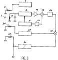
C'est ce qu'on trouve dans le schéma de la figure 6 où apparaissent, en plus des moyens déjà représentés sur la figure 4, un intégrateur 31 et un enroulement 32 de contre-réaction. Dans un tel appareil, le champ total est toujours maintenu à la valeur correspondant à la résonance et le signal d'erreur intégré constitue en fait le signal de mesure. Ce dernier apparaît sur la sortie 34 de l'appareil.This is what is found in the diagram of Figure 6 where appear, in addition to the means already shown in Figure 4, an
En d'autres termes, quel que soit le champ appliqué de l'extérieur à l'échantillon, cet échantillon voit, le long de la direction D, le même champ, à savoir celui qui assure la résonance des spins. Comme le champ correspondant à la résonance est beaucoup plus grand (plus de dix fois) que le champ d'origine extérieure à mesurer, le module de la somme vectorielle (cf. fig. 2) est sensiblement égal à la somme du champ crée par le courant de polarisation et dirigé selon la direction D et de la projection sur cette direction du champ extérieur à mesurer.In other words, whatever the field applied from the outside to the sample, this sample sees, along direction D, the same field, namely that which ensures the resonance of the spins. As the field corresponding to the resonance is much larger (more than ten times) than the field of external origin to be measured, the modulus of the vector sum (cf. fig. 2) is substantially equal to the sum of the field created by the bias current and directed in the direction D and of the projection onto this direction of the external field to be measured.
Autrement dit, les moyens 31 et 32 réalisent un asservissement de l'appareil à la résonance, quel que soit le champ appliqué de l'extérieur.In other words, the means 31 and 32 control the device to resonance, whatever the field applied from the outside.
On peut noter encore que, dans le mode de réalisation illustré sur la figure 6, les trois enroulements, respectivement de polarisation 3, d'agitation 24 et de contre-réaction 32, sont supposés distincts ; mais comme ils ont tous le même axe, ils peuvent très bien être confondus en un seul et même enroulement.It may also be noted that, in the embodiment illustrated in FIG. 6, the three windings, of
Quant à l'intégrateur 31, il peut soit délivrer directement le courant de contre-réaction, soit délivrer une tension, auquel cas il faut lui associer un convertisseur tension-courant, sous la forme par exemple d'une résistance.As for the
On retiendra de cet exposé de l'état de la technique, que les magnétomètres directionnels à résonance connus comprennent en général un échantillon à spins soumis au champ à mesurer, des moyens pour appliquer à cet échantillon un champ magnétique de polarisation, des moyens pour appliquer à l'échantillon un champ radiofréquence et exciter la résonance des spins, des moyens pour détecter cette résonance, des moyens pour engendrer un signal électrique antisymétrique qui s'annule lorsque le champ total appliqué à l'échantillon prend la valeur Ho correspondant à la résonance des spins et qui est positif ou négatif selon que le champ total appliqué est plus grand ou plus petit que cette valeur particulière (Ho). En l'absence de champ à mesurer, l'appareil est réglé pour être à la résonance. En présence d'un champ à mesurer, le champ de contre-réaction rétablit la résonance et la valeur du signal d'erreur intégré (ou du courant de contre-réaction) constitue la mesure du champ magnétique.It will be retained from this presentation of the state of the art, that known directional resonance magnetometers generally comprise a sample with spins subjected to the field to be measured, means for applying to this sample a field magnetic polarization, means for applying a radiofrequency field to the sample and exciting the resonance of the spins, means for detecting this resonance, means for generating an asymmetric electrical signal which is canceled out when the total field applied to the sample takes the value Ho corresponding to the resonance of the spins and which is positive or negative depending on whether the total field applied is larger or smaller than this particular value (Ho). If there is no field to measure, the device is set to be at resonance. In the presence of a field to be measured, the feedback field restores the resonance and the value of the integrated error signal (or of the feedback current) constitutes the measurement of the magnetic field.
Bien que donnant satisfaction à certains égards, ces magnétomètres présentent néanmoins des inconvénients. En particulier, ils sont de caractère analogique, de sorte que si l'on veut disposer d'une mesure en numérique, il faut leur associer un convertisseur analogique-numérique. Or, dans l'état actuel de ces composants, il ne semble pas que la précision de ces convertisseurs soit adaptée à la très grande précision requise pour certains magnétomètres. En effet, lorsqu'il s'agit de mesurer, par exemple, le champ magnétique terrestre, dont la valeur est d'environ 50 microteslas, l'erreur tolérée est de 10 picoteslas. Ceci impose donc une résolution de 0,2 pour mille. Une telle précision correspond à un convertisseur analogique-numérique de 22 bits, lequel n'existe pas dans l'état actuel de la technique.Although satisfactory in certain respects, these magnetometers nevertheless have drawbacks. In particular, they are of analog character, so that if one wants to have a measurement in digital, it is necessary to associate an analog-digital converter to them. However, in the current state of these components, it does not seem that the precision of these converters is adapted to the very high precision required for certain magnetometers. Indeed, when it comes to measuring, for example, the Earth's magnetic field, the value of which is around 50 microteslas, the error tolerated is 10 picoteslas. This therefore requires a resolution of 0.2 per thousand. Such precision corresponds to a 22-bit analog-digital converter, which does not exist in the current state of the art.
La présente invention a justement pour but de remédier à cet inconvénient. A cette fin, elle propose un magnétomètre qui comprend, intrinsèquement, des moyens numériques tels que le signal délivré par l'appareil soit non seulement déjà en numérique, mais corresponde à une précision adaptée aux grandes performances de l'appareil.The object of the present invention is precisely to remedy this drawback. To this end, it offers a magnetometer which intrinsically comprises digital means such that the signal delivered by the device is not only already digital, but corresponds to an accuracy adapted to the high performance of the device.
Ce résultat est obtenu, selon l'invention, par l'utilisation de moyens au moins en partie numérique pour former le signal d'erreur et établir la contre-réaction qui ramènera le magnétomètre à la résonance.This result is obtained, according to the invention, by the use of means at least partially digital to form the error signal and establish the feedback which will bring the magnetometer to resonance.
En l'absence de champ à mesurer, et comme dans l'art antérieur décrit plus haut, pour obtenir la résonance des spins à la fréquence fo du générateur d'excitation, on applique à l'échantillon un champ Ho défini par 2πfo/γ. Ceci peut être obtenu par tout moyen approprié. Lorsqu'un champ à mesurer est appliqué à l'échantillon, la résonance disparaît. Pour la retrouver, il faut établir un courant de contre-réaction à partir du signal d'erreur obtenu. Selon l'invention, cette fonction est remplie par des moyens logiques et numériques. Un signal d'erreur numérique est engendré sous forme d'un nombre à plusieurs digits. A partir de ce nombre, un courant de contre-réaction est formé qui, appliqué à l'un des enroulements prévus classiquement, permet de rétablir la résonance. Le passage par la résonance est détecté par un organe logique qui bloque le nombre à sa valeur correspondante, celle-ci étant alors la traduction du champ à mesurer. On obtient donc ainsi directement la valeur du champ magnétique en numérique.In the absence of a field to be measured, and as in the prior art described above, to obtain the resonance of the spins at the frequency fo of the excitation generator, a field Ho defined by 2πfo / γ is applied to the sample. . This can be achieved by any suitable means. When a field to be measured is applied to the sample, the resonance disappears. To find it, a feedback current must be established from the error signal obtained. According to the invention, this function is fulfilled by logical and digital means. A digital error signal is generated as a multi-digit number. From this number, a feedback current is formed which, applied to one of the conventionally provided windings, makes it possible to restore the resonance. The passage through resonance is detected by a logical organ which blocks the number at its corresponding value, this then being the translation of the field to be measured. We thus obtain directly the value of the magnetic field in digital.
Selon l'invention, le champ de polarisation Ho est créé soit par des moyens de polarisation (dans ce cas il se superpose au champ de contre-réaction lorsqu'il existe), soit par des moyens de contre-réaction qui engendrent alors un champ correspondant à la somme de Ho et du champ de contre-réaction.According to the invention, the polarization field Ho is created either by polarization means (in this case it is superimposed on the feedback field when it exists), or by feedback means which then generate a field corresponding to the sum of Ho and the field feedback.
- la figure 1 montre une variante de magnétomètre directionnel à résonance selon l'art antérieur ;FIG. 1 shows a variant of a directional resonance magnetometer according to the prior art;
- la figure 2 montre la composition des différents champs en présence ;FIG. 2 shows the composition of the different fields present;
- la figure 3 illustre une courbe de dispersion autour de la résonance ;FIG. 3 illustrates a dispersion curve around the resonance;
- la figure 4 montre une autre variante de magnétomètre selon l'art antérieur, à champ d'agitation ;FIG. 4 shows another variant of magnetometer according to the prior art, with a stirring field;
- la figure 5 illustre la courbe de dispersion obtenue avec un magnétomètre de ce dernier type ;FIG. 5 illustrates the dispersion curve obtained with a magnetometer of this latter type;
- la figure 6 montre encore une autre variante de magnétomètre selon l'art antérieur à champ d'agitation et à champ de contre-réaction ;FIG. 6 shows yet another variant of a magnetometer according to the prior art with a stirring field and a feedback field;
- la figure 7 est un schéma général d'un magnétomètre conforme à l'invention ;Figure 7 is a general diagram of a magnetometer according to the invention;
- la figure 8 illustre un premier mode de réalisation d'un magnétomètre à additionneur de courant,FIG. 8 illustrates a first embodiment of a magnetometer with current adder,
- la figure 9 est un schéma explicatif du dispositif de la figure précédente ;Figure 9 is an explanatory diagram of the device of the previous figure;
- la figure 10 illustre un deuxième mode de réalisation d'un magnétomètre à enroulement spécifique de contre-réaction ;FIG. 10 illustrates a second embodiment of a magnetometer with a specific feedback winding;
- la figure 11 illustre un autre mode de réalisation à étalonnage numérique ;FIG. 11 illustrates another embodiment with digital calibration;
- la figure 12 illustre un algorithme de formation d'un nombre par pas successifs ;FIG. 12 illustrates an algorithm for forming a number in successive steps;
- la figure 13 illutre un algorithme de formation d'un nombre par approximations successives ;FIG. 13 illustrates an algorithm for forming a number by successive approximations;
- la figure 14 illustre un algorithme à deux nombres successifs, respectivement positif et négatif ;FIG. 14 illustrates an algorithm with two successive numbers, respectively positive and negative;
- la figure 15 illustre un mode de réalisation à deux nombres et à deux convertisseurs numérique-analogique et à additionneur de courant ;FIG. 15 illustrates an embodiment with two numbers and with two digital-analog converters and with current adder;
- la figure 16 illustre encore un mode de réalisation à deux nombres et à deux convertisseurs numérique-analogique mais à deux enroulements spécifiques ;FIG. 16 also illustrates an embodiment with two numbers and two digital-analog converters but with two specific windings;
- la figure 17 illustre un algorithme de fonctionnement à deux nombres ;Figure 17 illustrates a two number operation algorithm;
- la figure 18 montre un exemple de circuit logique utilisable dans l'invention ;FIG. 18 shows an example of a logic circuit usable in the invention;
- la figure 19 est un diagramme explicatif du fonctionnement du circuit logique de la figure précédente.Figure 19 is an explanatory diagram of the operation of the logic circuit of the previous figure.
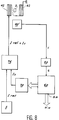
La figure 7 est un schéma général d'un magnétomètre conforme à l'invention. Les moyens déjà utilisés dans l'art antérieur sont symbolisés par un bloc référencé 40. Il faut comprendre qu'il s'agit des moyens déjà décrits à propos des figures 1, 4 et 6, pris seuls ou en combinaison, et qui permettent d'exciter la résonance, de la détecter et de fournir un signal V s'annulant lorsque le champ magnétique total prend la valeur Ho correspondant à la résonance.Figure 7 is a general diagram of a magnetometer according to the invention. The means already used in the prior art are symbolized by a block referenced 40. It must be understood that these are the means already described with reference to FIGS. 1, 4 and 6, taken alone or in combination, and which allow d excite the resonance, detect it and supply a signal V canceling out when the total magnetic field takes the value Ho corresponding to the resonance.
Le magnétomètre de l'invention est caractérisé par un circuit logique 50, qui reçoit le signal en question et délivre un signal logique S pouvant prendre deux états logiques EL1, EL2, le second indiquant que le signal V s'est annulé, c'est-à-dire qu'on est passé à la résonance.The magnetometer of the invention is characterized by a
Le magnétomètre de l'invention comprend encore un processeur (ou contrôleur) 60, qui reçoit le signal logique S et délivre un signal numérique N, autrement dit un nombre à plusieurs bits (par exemple 8 ou 16 bits ou plus).The magnetometer of the invention also comprises a processor (or controller) 60, which receives the logic signal S and delivers a digital signal N, in other words a number with several bits (for example 8 or 16 bits or more).
Ce processeur 60 délivre par ailleurs, sur une sortie de mesure notée SM, un nombre qui a la valeur mémorisée prise finalement par le nombre N lorsque la résonance a eu lieu.This
Le magnétomètre de l'invention comprend encore un convertisseur numérique-analogique 70, qui reçoit le nombre N et le transforme en courant I (soit directement, soit par l'intermédiaire d'une tension, elle-même convertie ensuite en courant). Le courant I alimente un enroulement 42 disposé à proximité de l'échantillon 2. Il faut comprendre que cet enroulement 42 peut être soit un enroulement spécifique, ajouté aux autres enroulements existant classiquement dans un magnétomètre (tels qu'ils ont été représentés sur la figure 6 sous les références 3 et 24), soit l'un quelconque de ces enroulements puisqu'il s'agit de créer un champ de contre-réaction devant être dirigé selon la direction générale D commune à tous ces enroulements.The magnetometer of the invention also comprises a digital-
Le fonctionnement général de l'appareil de la figure 7 est alors le suivant.The general operation of the apparatus of FIG. 7 is then as follows.
Lorsque le champ magnétique à mesurer est nul, le courant de polarisation est réglé pour qu'on soit à la résonance. Alors, la tension V est nulle et le signal logique S délivré par le circuit 50 est dans son second état logique EL2. Le processeur 60 délivre un nombre N nul. Aucun courant de contre-réaction I n'est appliqué à l'enroulement 42.When the magnetic field to be measured is zero, the bias current is adjusted so that we are at resonance. Then, the voltage V is zero and the logic signal S delivered by the
Lorsqu'un champ Hm est appliqué à l'échantillon, la résonance ne se produit plus, la tension V n'est plus nulle mais prend une valeur qui constitue un signal d'erreur. Le signal logique S passe dans son premier état logique EL1. Le processeur 60 incrémente alors le nombre N (en positif ou en négatif) par un algorithme approprié, de telle sorte qu'un courant soit appliqué à l'enroulement 42. Il en résulte un champ de contre-réaction qui modifie le champ total appliqué à l'échantillon 2 jusqu'à ce que la projection de Hm sur la direction D soit exactement compensée par le champ de contre-réaction. Alors, la tension V repasse par zéro, le signal logique S reprend son second état logique EL2 indiquant au processeur 60 que la résonance a été rétablie. Le processeur bloque alors le nombre N à la valeur prise Nm et délivre cette valeur Nm sur la sortie de mesure SM. Cette valeur Nm est la valeur en numérique de la projection du champ Hm à mesurer sur la direction D.When an Hm field is applied to the sample, the resonance no longer occurs, the voltage V is no longer zero but takes a value which constitutes an error signal. The logic signal S goes into its first logic state EL1. The
Si l'on désigne par bo la valeur du champ magnétique obtenue pour un nombre N égal à 1 (c'est-à-dire lorsque le bit le moins significatif de N est à 1, les autres bits étant tous à 0), le champ mesuré correspondant à la valeur finale Nm est égal à Nmbo+ , où est un terme d'erreur inférieur à bo.If we denote by bo the value of the magnetic field obtained for a number N equal to 1 (that is to say when the least significant bit of N is at 1, the other bits all being at 0), the measured field corresponding to the final value Nm is equal to Nmbo +, where is an error term less than bo.
Dans le schéma de la figure 7, les moyens d'assurer la résonance par réglage du champ de polarisation ne sont pas représentés explicitement et sont supposés contenus dans le moyen général 40 qui contient donc la source de courant permettant de créer ce champ de polarisation via l'enroulement 3.In the diagram of FIG. 7, the means of ensuring resonance by adjusting the polarization field are not shown explicitly and are assumed to be contained in the general means 40 which therefore contains the current source making it possible to create this polarization field via the winding 3.
Dans le schéma de la figure 8, au contraire, la source de courant de référence 5 qui permet de créer ce champ via l'enroulement 42 est explicitement représentée (le moyen général dépourvu de cette source est alors référencé 40'). Le courant de référence Iref est réglé à une valeur Io. On ajoute à ce courant le courant I1 délivré par le convertisseur 70 et ceci dans un additionneur 76 qui délivre la somme Io+I1, laquelle est appliquée à l'enroulement 42.In the diagram of FIG. 8, on the contrary, the reference
La figure 9 montre les variations de quelques signaux apparaissant dans les dispositifs des figures 7 et 8.FIG. 9 shows the variations of some signals appearing in the devices of FIGS. 7 and 8.
Sur la partie (a) tout d'abord, le courant de référence Iref délivré par la source 5 est porté en abscisses et le signal logique S est en ordonnées. Si, en l'absence de champ à mesurer, le courant Iref est inférieur à la valeur Io correspondant à la résonance, le signal S est dans son premier état logique EL1. Si le courant Iref franchit la valeur Io, le signal S bascule et prend son second état logique EL2.On part (a) first of all, the reference current Iref delivered by the
Toujours en l'absence de champ à mesurer, le courant I1 (partie b) délivré par le convertisseur 70, est nul.Still in the absence of a field to be measured, the current I1 (part b) delivered by the
En cas de champ à mesurer, il faut un courant I1 égal à -Im pour obtenir à nouveau la résonance, c'est-à-dire pour faire basculer le signal logique S de l'état EL1 à l'état EL2 (partie c).In the case of a field to be measured, a current I1 equal to -Im is required to obtain resonance again, that is to say to switch the logic signal S from state EL1 to state EL2 (part c ).
Le mode de réalisation de la figure 8 est simple mais il est tributaire de la stabilité de la source 5. La précision de la mesure dépend de la valeur de bo et de la capacité du convertisseur 70, laquelle doit correspondre à la valeur maximum du champ Hm. Une erreur peut s'introduire lors de la variation de bo.The embodiment of FIG. 8 is simple but it is dependent on the stability of the
Dans la variante de réalisation illustrée sur la figure 10, les moyens de formation du champ de polarisation et ceux du champ de contre-réaction sont séparés : les premiers sont constitués par la source 5 située dans le moyen général 40 et l'enroulement référencé 3, tandis que les seconds sont constitués par le convertisseur 70 et l'enroulement spécifique 42.In the variant embodiment illustrated in FIG. 10, the means for forming the polarization field and those for the feedback field are separated: the first are constituted by the
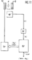
Dans la variante de la figure 11, les moyens numériques remplissent non seulement la fonction de mesure mais encore celle d'étalonnage préalable. Pour cela, lorsque le champ à mesurer Hm est absent, le processeur délivre un nombre N de valeur No correspondant à la résonance. Le champ appliqué est alors Nobo+ ε (où ε est encore un terme d'erreur majoré par bo). En présence d'un champ à mesurer Hm, le processeur rétablit la résonance en formant un nombre Nm différent de No et apte à créer un champ de contre-réaction de valeur (Nm-No)bo qui s'opposera à la composante du champ à mesurer selon la direction D. La valeur numérique du champ sera donnée par (Nm-No). C'est elle qui apparaît sur la sortie de mesure SM du processeur 60. L'erreur commise est alors inférieure à 2bo.In the variant of FIG. 11, the digital means fulfill not only the measurement function but also that of prior calibration. For this, when the field to be measured Hm is absent, the processor delivers a number N of value No corresponding to the resonance. The applied field is then Nobo + ε (where ε is still an error term increased by bo). In the presence of a field to be measured Hm, the processor restores the resonance by forming a number Nm different from No and able to create a value feedback field (Nm-No) bo which will oppose the component of the field to be measured in direction D. The numerical value of the field will be given by (Nm-No). It is this which appears on the measurement output SM of
Ce mode de réalisation présente l'inconvénient de nécessiter un nombre No beaucoup plus grand que Nm (car le champ de polarisation est, dans ce genre d'appareil et comme déjà souligné, très supérieur au champ à mesurer). Il faut donc utiliser un convertisseur 70 à grande dynamique. Pour une valeur du champ à mesurer de 100 µT et une valeur de champ de polarisation de 1 mT, on obtient, comme excursion maximale du convertisseur, 1,1 mT, ce qui donne une résolution minimale, pour un convertisseur de 16 bits :![]()
ou encore, pour un convertisseur de 20 bits, environ 1 nT.This embodiment has the disadvantage of requiring a number No much greater than Nm (because the polarization field is, in this type of device and as already pointed out, much greater than the field to be measured). It is therefore necessary to use a ![]()
or, for a 20-bit converter, about 1 nT.
Cette résolution est malheureusement supérieure à la résolution que l'on peut attendre d'un magnétomètre directionnel à résonance. On utilisera donc avantageusement des variantes à plusieurs convertisseurs comme il sera décrit plus bas.This resolution is unfortunately higher than the resolution that one would expect from a directional resonance magnetometer. Variants with several converters will therefore advantageously be used as will be described below.
Un deuxième inconvénient du mode de réalisation de la figure 11 est lié à l'étalonnage préalable effectué de manière numérique. Si bo varie, la mesure peut se trouver erronée. Ce problème peut être résolu en effectuant deux mesures successives, l'une avec un champ de polarisation dirigé dans un sens, l'autre avec un champ dirigé dans l'autre sens. On obtient alors, en sortie du processeur, successivement deux nombres, noté N⁺m et N⁻m avec les relations suivantes :![]()
![]()
ce qui donne la valeur du champ à mesurer Hm indépendamment de bo :![]()
où ε' est un terme d'erreur inférieur à 2bo.A second drawback of the embodiment of FIG. 11 is linked to the prior calibration carried out digitally. If bo varies, the measurement may be wrong. This problem can be solved by carrying out two successive measurements, one with a polarization field directed in one direction, the other with a field directed in the other direction. We then obtain, at the output of the processor, successively two numbers, noted N⁺m and N⁻m with the following relationships: ![]()
![]()
which gives the value of the field to be measured Hm independently of bo: ![]()
where ε 'is an error term less than 2bo.
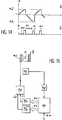
Tout algorithme convient pour incrémenter ou décrémenter le nombre N jusqu'à l'apparition de la résonance. A titre d'exemples non limitatifs, les figures 12 et 13 illustrent des algorithmes respectivement à pas successifs et à approximations successives et la figure 14 un algorithme à pas successifs et à deux nombres.Any algorithm is suitable for incrementing or decrementing the number N until the appearance of resonance. By way of nonlimiting examples, FIGS. 12 and 13 illustrate successive step and successive approximation algorithms respectively and FIG. 14 a step algorithm successive and two numbers.
Sur la figure 12, tout d'abord, on voit, sur la partie (a), le champ H incrémenté pas à pas avec une amplitude bo, qui correspond au bit le moins significatif du nombre N. Ce nombre N croît ainsi d'une unité à chaque échantillonnage, lequel est défini par une horloge contenue dans le processeur. Pendant cette incrémentation, le signal logique S délivré par le circuit logique 50 et montré sur la partie (b) de la figure 12, demeure dans son premier état logique EL1, en l'occurrence l'état bas.In FIG. 12, first of all, we see, on part (a), the field H incremented step by step with an amplitude bo, which corresponds to the least significant bit of the number N. This number N thus increases by a unit for each sampling, which is defined by a clock contained in the processor. During this incrementation, the logic signal S delivered by the
Cependant, lorsque le champ total atteint la valeur Ho correspondant à la résonance, le signal S bascule sur son deuxième état logique EL2, en l'occurrence l'état haut, et le processeur bloque l'incrémentation du nombre N. L'arrêt se maintient pendant une durée D pour permettre la mémorisation du nombre obtenu.However, when the total field reaches the value Ho corresponding to the resonance, the signal S switches to its second logic state EL2, in this case the high state, and the processor blocks the incrementation of the number N. The stop is holds for a duration D to allow the memorization of the number obtained.
Le nombre N est ensuite remis à zéro, ce qui fait rebasculer le circuit logique 50 sur l'état EL1 et l'incrémentation reprend.The number N is then reset to zero, which switches the
Sur la figure 13 est schématisé un algorithme par approximations successives, qui permet d'obtenir plus rapidement la valeur recherchée. Au lieu d'agir en premier lieu sur le bit le moins significatif de N, comme dans la variante de la figure 12, on agit sur le bit le plus significatif et on teste le signal S. Si celui-ci est passé à son second niveau logique EL2, indiquant que la résonance a été franchie, le bit le plus significatif est remis à zéro, sinon il est laissé à 1 et le bit suivant de poids plus faible est commuté de 0 à 1. A nouveau, si le signal S indique que la résonance a été dépassée, le second bit est remis à 0 sinon il est laissé à 1. La procédure se poursuit ainsi jusqu'au bit de plus faible poids. Dans le cas illustré sur la figure 13, le bit le plus significatif n'a pas permis, à lui seul, d'atteindre la résonance mais le bit suivant a permis de la dépasser. Il a donc été ramené à 0. De même pour le troisième bit (dans l'ordre des poids décroissants). Le quatrième bit, en revanche, a été maintenu à 1 ; mais le cinquième a été remis à 0 etc.In FIG. 13 is diagrammed an algorithm by successive approximations, which makes it possible to obtain the desired value more quickly. Instead of acting first on the least significant bit of N, as in the variant in FIG. 12, we act on the most significant bit and test the signal S. If this has passed to its second logic level EL2, indicating that the resonance has been crossed, the most significant bit is reset to zero, otherwise it is left at 1 and the next least significant bit is switched from 0 to 1. Again, if the signal S indicates that the resonance has been exceeded, the second bit is reset to 0 otherwise it is left at 1. The procedure thus continues until the least significant bit. In the case illustrated in FIG. 13, the most significant bit alone did not make it possible to reach the resonance but the next bit made it possible to exceed it. It has therefore been reduced to 0. Likewise for the third bit (in the order of decreasing weights). The fourth bit, on the other hand, was kept at 1; but the fifth has been reset to 0 etc.
Comme dans le cas de la figure 12, lorsque la valeur correspondant à la résonance est atteinte, la valeur de N obtenue est mémorisée et affichée sur la sortie du processeur. Le nombre N est ensuite remis à 0.As in the case of FIG. 12, when the value corresponding to the resonance is reached, the value of N obtained is memorized and displayed on the output of the processor. The number N is then reset to 0.
Lorsqu'on travaille avec deux nombres successifs de signes opposés, comme expliqué plus haut, afin d'éliminer l'étalonnage préalable sur bo, on peut utiliser les algorithmes précédents, (figs. 12 et 13) ou tout autre. A titre d'exemple, la figure 14 montre comment on recherche les deux nombres N⁺m et N⁻m par approximations successives, d'abord pour le nombre positif N⁺, ensuite pour le nombre négatif N⁻ (partie (a)). La partie (b) de la figure montre l'allure du signal logique S et les périodes D⁺ et D⁻ de mémorisation des nombres positif et négatif obtenus.When working with two successive numbers of opposite signs, as explained above, in order to eliminate the previous calibration on bo, one can use the previous algorithms, (figs. 12 and 13) or any other. For example, Figure 14 shows how we search for the two numbers N⁺m and N⁻m by successive approximations, first for the positive number N⁺, then for the negative number N⁻ (part (a)) . Part (b) of the figure shows the shape of the logic signal S and the periods D⁺ and D⁻ of memorization of the positive and negative numbers obtained.
Dans les variantes qui viennent d'être décrites un seul convertisseur numérique-analogique est utilisé. Dans une variante plus complexe, on peut utiliser deux convertisseurs de poids différents. C'est ce qui est représenté sur les figures 15 et 16 où les deux convertisseurs portent les références 70₁ et 70₂. Ils délivrent respectivement des courants I₁ et I₂. La différence entre les deux modes de réalisation illustrés tient à ce que, dans le premier cas (fig.15), les deux courants I₁ et I₂ sont ajoutés l'un à l'autre dans un additionneur 75, la somme résultante étant appliquée à un seul enroulement 42 alors que, dans le second cas (fig. 16), chaque courant I₁, I₂ alimente un enroulement spécifique respectivement 42₁, 42₂.In the variants which have just been described, only one digital-analog converter is used. In a more complex variant, two converters of different weights can be used. This is what is shown in FIGS. 15 and 16 where the two converters bear the
Un algorithme particulier valable pour les variantes à deux convertisseurs de poids différents est illustré sur la figure 17. Le deuxième convertisseur 70₂ est supposé posséder une unité bo2 telle que bo2 soit supérieure à bo1/Nm2. Cette variante permet une mesure absolue du champ avec une résolution égale à (Ho+Hmmax)/2(Nmax1+Nmax2), où Hmmax est l'amplitude maximale du champ à mesurer et Nmax1 et Nmax2 sont les valeurs maximales des nombres N1 et N2 appliqués aux deux convertisseurs. La séquence des opérations est la suivante :
- 1) incrémentation du convertisseur 70₁ de plus grand poids dans le sens positif jusqu'au delà de la résonance ; mesure de N₁⁺ et maintient de cette valeur ;
- 2) incrémentation du convertisseur de plus faible poids 70₂ dans le sens négatif (autrement dit décrémentation) jusqu'au delà de la résonance ; mesure de N₂⁺ ;
- 3) positionnement du premier convertisseur 70₁ à N₁⁺-1 ;
- 4) incrémentation du convertisseur de plus faible poids 70₂ dans le sens positif jusqu'au delà de la résonance ; mesure de N₂⁺.
- 1) incrementation of the
converter 70 convertisseur of greater weight in the positive direction until beyond the resonance; measure of N₁⁺ and maintain this value; - 2) incrementation of the converter of
least weight 70₂ in the negative direction (in other words decrementation) until beyond the resonance; measure of N₂⁺; - 3) positioning of the
first converter 70₁ to N₁⁺-1; - 4) incrementation of the converter of
least weight 70₂ in the positive direction until beyond the resonance; measure of N₂⁺.
On tire des nombres ainsi obtenus les relations :![]()
![]()
La relation (2) permet de relier bo1 à bo2. Les termes d'erreur n'ont pas été écrits, mais sont majorés par bo2.We draw from the numbers thus obtained the relations: ![]()
![]()
The relation (2) makes it possible to connect bo1 to bo2. The error terms were not written, but are increased by bo2.
Une séquence analogue dans le sens négatif permet d'obtenir :![]()
![]()
Ce qui permet de calculer Hm :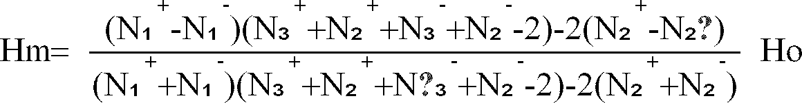
en utilisant une moyenne de (2) et (4) pour minimiser l'erreur sur la relation entre bo1 et bo2.An analogous sequence in the negative direction makes it possible to obtain: ![]()
![]()
Which allows to calculate Hm:
using an average of (2) and (4) to minimize the error on the relationship between bo1 and bo2.
D'autres algorithmes ou d'autres variantes de réalisation peuvent être utilisées. Elles peuvent être déduites d'algorithmes de conversion numérique-analogique connus.Other algorithms or other variant embodiments can be used. They can be deduced from known digital-analog conversion algorithms.
Quant au circuit logique 50 destiné à produire le signal logique S, l'homme du métier pourra aisément en concevoir la structure. A titre d'exemple, la figure 18 montre un mode de réalisation possible de ce circuit. Il s'agit d'un circuit comprenant un comparateur-inverseur 80 alimenté en ± 5 volts et tel que sa tension de sortie soit égale à -5 V lorsque sa tension d'entrée est faiblement positive et égale à+ 5 V lorsque sa tension d'entrée est faiblement négative. Ce comparateur est suivi d'une diode 82 chargée par une résistance 84, l'ensemble permettant de ne retenir que la valeur positive de la tension de sortie du comparateur.As for the
Les tensions apparaissant en différents points du circuit sont représentées sur la figure 19 : en (a) est représentée la tension d'entrée V (qui est la tension antisymétrique fournie par les moyens 40) (cf. figures 3 et 5), en (b) la tension VA au point A à la sortie du comparateur-inverseur 80, et en (c) le signal logique S délivré finalement par le circuit 50.The voltages appearing at different points of the circuit are represented in FIG. 19: in (a) is represented the input voltage V (which is the asymmetric voltage supplied by the means 40) (cf. FIGS. 3 and 5), in ( b) tension VA at point A at the output of the comparator-
Claims (14)
Applications Claiming Priority (2)
| Application Number | Priority Date | Filing Date | Title |
|---|---|---|---|
| FR9303008A FR2702844B1 (en) | 1993-03-16 | 1993-03-16 | Directional digital resonance magnetometer. |
| FR9303008 | 1993-03-16 |
Publications (1)
| Publication Number | Publication Date |
|---|---|
| EP0616227A1 true EP0616227A1 (en) | 1994-09-21 |
Family
ID=9445004
Family Applications (1)
| Application Number | Title | Priority Date | Filing Date |
|---|---|---|---|
| EP94400546A Withdrawn EP0616227A1 (en) | 1993-03-16 | 1994-03-14 | Digital directional resonance magnetometer |
Country Status (4)
| Country | Link |
|---|---|
| US (1) | US5455511A (en) |
| EP (1) | EP0616227A1 (en) |
| CA (1) | CA2117162A1 (en) |
| FR (1) | FR2702844B1 (en) |
Families Citing this family (3)
| Publication number | Priority date | Publication date | Assignee | Title |
|---|---|---|---|---|
| FR2707014B1 (en) * | 1993-06-24 | 1995-09-22 | Commissariat Energie Atomique | |
| US6239596B1 (en) | 1997-06-09 | 2001-05-29 | Joseph J. Stupak, Jr. | Total magnetic flux measuring device |
| DE102004010003A1 (en) * | 2004-03-01 | 2005-09-29 | Siemens Ag | Automation system and method for detecting and correcting connection errors |
Citations (3)
| Publication number | Priority date | Publication date | Assignee | Title |
|---|---|---|---|---|
| EP0240221A2 (en) * | 1986-03-24 | 1987-10-07 | Kabushiki Kaisha Toshiba | Measuring magnetic fields using NMR principles |
| EP0463919A1 (en) * | 1990-06-25 | 1992-01-02 | Commissariat A L'energie Atomique | Directional resonance magnetometer |
| EP0522191A1 (en) * | 1991-07-11 | 1993-01-13 | Spectrospin Ag | Method and apparatus for compensating field disturbances in magnetic fields |
Family Cites Families (3)
| Publication number | Priority date | Publication date | Assignee | Title |
|---|---|---|---|---|
| GB1165285A (en) * | 1966-02-08 | 1969-09-24 | Licentia Gmbh | Method of Measuring Very Small Differences in Field Strength by Means of a Nuclear-Resonance Magnetic-Field Measuring Instrument |
| FR2660074B1 (en) * | 1990-03-23 | 1992-06-12 | Commissariat Energie Atomique | IMPROVED SHIELDED MAGNETOMETER. |
| FR2678069A1 (en) * | 1991-06-18 | 1992-12-24 | Commissariat Energie Atomique | CURRENT SENSOR USING A DIRECTIONAL RESONANCE MAGNETOMETER. |
-
1993
- 1993-03-16 FR FR9303008A patent/FR2702844B1/en not_active Expired - Fee Related
-
1994
- 1994-02-28 US US08/202,590 patent/US5455511A/en not_active Expired - Fee Related
- 1994-03-07 CA CA002117162A patent/CA2117162A1/en not_active Abandoned
- 1994-03-14 EP EP94400546A patent/EP0616227A1/en not_active Withdrawn
Patent Citations (3)
| Publication number | Priority date | Publication date | Assignee | Title |
|---|---|---|---|---|
| EP0240221A2 (en) * | 1986-03-24 | 1987-10-07 | Kabushiki Kaisha Toshiba | Measuring magnetic fields using NMR principles |
| EP0463919A1 (en) * | 1990-06-25 | 1992-01-02 | Commissariat A L'energie Atomique | Directional resonance magnetometer |
| EP0522191A1 (en) * | 1991-07-11 | 1993-01-13 | Spectrospin Ag | Method and apparatus for compensating field disturbances in magnetic fields |
Non-Patent Citations (3)
| Title |
|---|
| A.E. PRYAKHIN: "TRACKING NUCLEAR MAGNETIC RESONANCE MAGNETOMETER WITH DIGITAL READOUT IN GAUSS", INSTRUMENTS AND EXPERIMENTAL TECHNIQUES., vol. 24, no. 6, 1 November 1981 (1981-11-01), NEW YORK US, pages 1467 - 1472 * |
| E.V. DVORNIKOV: "LARGE-SCALE AUTOMATION OF A NUCLEAR MAGNETIC RESONANCE MAGNETOMETER", INSTRUMENTS AND EXPERIMENTAL TECHNIQUES., vol. 22, no. 2, 1 March 1979 (1979-03-01), NEW YORK US, pages 504 - 508 * |
| J. KUBIAK ET AL.: "A NEW FIELD-TRACKING NMR MAGNETOMETER SYSTEM", JOURNAL OF PHYSICS E. SCIENTIFIC INSTRUMENTS, vol. 12, no. 7, 1 July 1979 (1979-07-01), BRISTOL GB, pages 640 - 643 * |
Also Published As
| Publication number | Publication date |
|---|---|
| US5455511A (en) | 1995-10-03 |
| FR2702844B1 (en) | 1995-05-12 |
| CA2117162A1 (en) | 1994-09-17 |
| FR2702844A1 (en) | 1994-09-23 |
Similar Documents
| Publication | Publication Date | Title |
|---|---|---|
| EP0455530B1 (en) | Fibre optical measuring device, gyroscope, navigation and stabilisation system, current sensor | |
| EP0430747B1 (en) | Fiber optic measuring device, gyroscope and system for navigation and stabilisation | |
| EP2426563B1 (en) | Method for calibrating a device with atomic operation | |
| EP0289414A2 (en) | Method and device for the digitization and linearization of a quasi-sinusoidal sensor | |
| FR2678069A1 (en) | CURRENT SENSOR USING A DIRECTIONAL RESONANCE MAGNETOMETER. | |
| FR2923007A1 (en) | SELF-CALIBRATION NUCLEAR MAGNETIC RESONANCE GYROSCOPE | |
| EP0293310B1 (en) | Method to calibrate an electronic dynamometric wrench | |
| EP0463919B1 (en) | Directional resonance magnetometer | |
| WO2012156016A1 (en) | Differential voltage measurement | |
| EP0750176B1 (en) | Apparatus for measuring an angular speed | |
| EP0656545B1 (en) | Magnetometer with polarized light and a coupled radiofrequency field | |
| EP0579537B1 (en) | Magnetometer with polarized light and servo-controlled radio frequency field | |
| EP0616227A1 (en) | Digital directional resonance magnetometer | |
| FR2800869A1 (en) | Hemispherical resonator gyroscope (HRG) or other vibrating sensor has analysis electronics that enable the second harmonic to be eliminated allowing more precise measurements to be made | |
| EP0614091A1 (en) | Directional resonance magnetometer | |
| CA1292278C (en) | Nuclear magnetic resonance magnetometer | |
| EP1995575A2 (en) | System for analysing the frequency of resonant devices | |
| EP1344075B1 (en) | Vector measurement of a magnetic field | |
| EP0515981B1 (en) | Apparatus for measuring an angular speed | |
| EP0324292A1 (en) | Continuous vector magnetometer with a capacitive magnetostrictive sensor, and its use as a gradient meter | |
| EP0616228A1 (en) | Multiaxial resonance magnetometer | |
| EP4075156A1 (en) | Method for using a magnetometer with zero field optical pumping operated in a non-zero ambient field | |
| FR2757951A1 (en) | Device for automatic balancing of magnetic coils used in NMR sensor | |
| EP4343281A1 (en) | Method for measuring an angular speed and/or an angular position | |
| FR2858060A1 (en) | Magnetic field intensity measuring process for electronic compass, involves plotting state change of resistivity resulting from reversal of magnetic moments of ferromagnetic layers at level of giant magnetic resistor |
Legal Events
| Date | Code | Title | Description |
|---|---|---|---|
| PUAI | Public reference made under article 153(3) epc to a published international application that has entered the european phase |
Free format text: ORIGINAL CODE: 0009012 |
|
| AK | Designated contracting states |
Kind code of ref document: A1 Designated state(s): BE CH DE DK GB LI SE |
|
| 17P | Request for examination filed |
Effective date: 19950223 |
|
| 17Q | First examination report despatched |
Effective date: 20000218 |
|
| STAA | Information on the status of an ep patent application or granted ep patent |
Free format text: STATUS: THE APPLICATION IS DEEMED TO BE WITHDRAWN |
|
| 18D | Application deemed to be withdrawn |
Effective date: 20000629 |