EP0616208A1 - Luminometer - Google Patents
Luminometer Download PDFInfo
- Publication number
- EP0616208A1 EP0616208A1 EP94301957A EP94301957A EP0616208A1 EP 0616208 A1 EP0616208 A1 EP 0616208A1 EP 94301957 A EP94301957 A EP 94301957A EP 94301957 A EP94301957 A EP 94301957A EP 0616208 A1 EP0616208 A1 EP 0616208A1
- Authority
- EP
- European Patent Office
- Prior art keywords
- reaction vessel
- disposed
- detectors
- housing
- sample
- Prior art date
- Legal status (The legal status is an assumption and is not a legal conclusion. Google has not performed a legal analysis and makes no representation as to the accuracy of the status listed.)
- Withdrawn
Links
- 238000006243 chemical reaction Methods 0.000 claims abstract description 82
- 230000003595 spectral effect Effects 0.000 claims abstract description 37
- 238000012360 testing method Methods 0.000 claims abstract description 37
- 239000003153 chemical reaction reagent Substances 0.000 claims abstract description 35
- 239000000126 substance Substances 0.000 claims abstract description 18
- 238000000034 method Methods 0.000 claims abstract description 17
- 239000000470 constituent Substances 0.000 claims abstract description 12
- 238000004020 luminiscence type Methods 0.000 claims abstract description 8
- 230000000977 initiatory effect Effects 0.000 claims abstract 2
- 239000000523 sample Substances 0.000 claims description 79
- 239000012530 fluid Substances 0.000 claims description 31
- 238000002347 injection Methods 0.000 claims description 10
- 239000007924 injection Substances 0.000 claims description 10
- 238000001514 detection method Methods 0.000 claims description 9
- 230000004044 response Effects 0.000 claims description 3
- 239000000203 mixture Substances 0.000 claims description 2
- 238000000429 assembly Methods 0.000 abstract description 33
- 230000000712 assembly Effects 0.000 abstract description 33
- 238000003556 assay Methods 0.000 description 62
- 239000012491 analyte Substances 0.000 description 25
- 102000009151 Luteinizing Hormone Human genes 0.000 description 24
- 108010073521 Luteinizing Hormone Proteins 0.000 description 24
- 150000001875 compounds Chemical class 0.000 description 24
- 229940040129 luteinizing hormone Drugs 0.000 description 24
- 239000000700 radioactive tracer Substances 0.000 description 24
- 102000012673 Follicle Stimulating Hormone Human genes 0.000 description 23
- 108010079345 Follicle Stimulating Hormone Proteins 0.000 description 23
- 229940028334 follicle stimulating hormone Drugs 0.000 description 23
- UEEJHVSXFDXPFK-UHFFFAOYSA-N N-dimethylaminoethanol Chemical class CN(C)CCO UEEJHVSXFDXPFK-UHFFFAOYSA-N 0.000 description 19
- 230000003287 optical effect Effects 0.000 description 19
- WEVYAHXRMPXWCK-UHFFFAOYSA-N Acetonitrile Chemical compound CC#N WEVYAHXRMPXWCK-UHFFFAOYSA-N 0.000 description 15
- 238000000295 emission spectrum Methods 0.000 description 13
- 239000000243 solution Substances 0.000 description 10
- 238000002834 transmittance Methods 0.000 description 10
- DZBUGLKDJFMEHC-UHFFFAOYSA-N acridine Chemical class C1=CC=CC2=CC3=CC=CC=C3N=C21 DZBUGLKDJFMEHC-UHFFFAOYSA-N 0.000 description 9
- 238000003018 immunoassay Methods 0.000 description 9
- 239000007790 solid phase Substances 0.000 description 8
- JEGZRTMZYUDVBF-UHFFFAOYSA-N Benz[a]acridine Chemical compound C1=CC=C2C3=CC4=CC=CC=C4N=C3C=CC2=C1 JEGZRTMZYUDVBF-UHFFFAOYSA-N 0.000 description 7
- 239000002253 acid Substances 0.000 description 6
- 230000009977 dual effect Effects 0.000 description 6
- 125000000217 alkyl group Chemical group 0.000 description 5
- 125000003118 aryl group Chemical group 0.000 description 5
- 230000005540 biological transmission Effects 0.000 description 5
- 125000005842 heteroatom Chemical group 0.000 description 5
- -1 amino, hydroxyl Chemical group 0.000 description 4
- 230000003321 amplification Effects 0.000 description 4
- 230000027455 binding Effects 0.000 description 4
- 239000000872 buffer Substances 0.000 description 4
- 238000012937 correction Methods 0.000 description 4
- 125000000524 functional group Chemical group 0.000 description 4
- 238000003199 nucleic acid amplification method Methods 0.000 description 4
- 239000002245 particle Substances 0.000 description 4
- 239000008363 phosphate buffer Substances 0.000 description 4
- 238000000159 protein binding assay Methods 0.000 description 4
- 125000001424 substituent group Chemical group 0.000 description 4
- XLYOFNOQVPJJNP-UHFFFAOYSA-N water Substances O XLYOFNOQVPJJNP-UHFFFAOYSA-N 0.000 description 4
- IJGRMHOSHXDMSA-UHFFFAOYSA-N Atomic nitrogen Chemical compound N#N IJGRMHOSHXDMSA-UHFFFAOYSA-N 0.000 description 3
- 102000003864 Human Follicle Stimulating Hormone Human genes 0.000 description 3
- 108010082302 Human Follicle Stimulating Hormone Proteins 0.000 description 3
- HEMHJVSKTPXQMS-UHFFFAOYSA-M Sodium hydroxide Chemical compound [OH-].[Na+] HEMHJVSKTPXQMS-UHFFFAOYSA-M 0.000 description 3
- 125000003342 alkenyl group Chemical group 0.000 description 3
- 125000000304 alkynyl group Chemical group 0.000 description 3
- 239000012736 aqueous medium Substances 0.000 description 3
- 125000003710 aryl alkyl group Chemical group 0.000 description 3
- 230000002068 genetic effect Effects 0.000 description 3
- 230000002452 interceptive effect Effects 0.000 description 3
- 239000003446 ligand Substances 0.000 description 3
- 239000007788 liquid Substances 0.000 description 3
- 125000000951 phenoxy group Chemical group [H]C1=C([H])C([H])=C(O*)C([H])=C1[H] 0.000 description 3
- 238000002360 preparation method Methods 0.000 description 3
- 239000000047 product Substances 0.000 description 3
- 238000011084 recovery Methods 0.000 description 3
- 230000035945 sensitivity Effects 0.000 description 3
- 210000002966 serum Anatomy 0.000 description 3
- 238000001228 spectrum Methods 0.000 description 3
- 208000032366 Oversensing Diseases 0.000 description 2
- PXIPVTKHYLBLMZ-UHFFFAOYSA-N Sodium azide Chemical compound [Na+].[N-]=[N+]=[N-] PXIPVTKHYLBLMZ-UHFFFAOYSA-N 0.000 description 2
- NINIDFKCEFEMDL-UHFFFAOYSA-N Sulfur Chemical compound [S] NINIDFKCEFEMDL-UHFFFAOYSA-N 0.000 description 2
- DZBUGLKDJFMEHC-UHFFFAOYSA-O acridine;hydron Chemical compound C1=CC=CC2=CC3=CC=CC=C3[NH+]=C21 DZBUGLKDJFMEHC-UHFFFAOYSA-O 0.000 description 2
- XAGFODPZIPBFFR-UHFFFAOYSA-N aluminium Chemical compound [Al] XAGFODPZIPBFFR-UHFFFAOYSA-N 0.000 description 2
- 229910052782 aluminium Inorganic materials 0.000 description 2
- 238000004458 analytical method Methods 0.000 description 2
- 239000000427 antigen Substances 0.000 description 2
- 102000036639 antigens Human genes 0.000 description 2
- 108091007433 antigens Proteins 0.000 description 2
- 238000002820 assay format Methods 0.000 description 2
- QVGXLLKOCUKJST-UHFFFAOYSA-N atomic oxygen Chemical compound [O] QVGXLLKOCUKJST-UHFFFAOYSA-N 0.000 description 2
- 230000008901 benefit Effects 0.000 description 2
- 230000008878 coupling Effects 0.000 description 2
- 238000010168 coupling process Methods 0.000 description 2
- 238000005859 coupling reaction Methods 0.000 description 2
- 239000003989 dielectric material Substances 0.000 description 2
- 239000003085 diluting agent Substances 0.000 description 2
- 239000012153 distilled water Substances 0.000 description 2
- 230000000694 effects Effects 0.000 description 2
- 238000011534 incubation Methods 0.000 description 2
- 238000003780 insertion Methods 0.000 description 2
- 230000037431 insertion Effects 0.000 description 2
- 239000000463 material Substances 0.000 description 2
- 239000011159 matrix material Substances 0.000 description 2
- 229910052757 nitrogen Inorganic materials 0.000 description 2
- 150000007523 nucleic acids Chemical group 0.000 description 2
- 229910052760 oxygen Inorganic materials 0.000 description 2
- 239000001301 oxygen Substances 0.000 description 2
- 238000003752 polymerase chain reaction Methods 0.000 description 2
- 102000004169 proteins and genes Human genes 0.000 description 2
- 108090000623 proteins and genes Proteins 0.000 description 2
- 239000010453 quartz Substances 0.000 description 2
- 239000011541 reaction mixture Substances 0.000 description 2
- 230000009467 reduction Effects 0.000 description 2
- 239000012488 sample solution Substances 0.000 description 2
- 238000000926 separation method Methods 0.000 description 2
- VYPSYNLAJGMNEJ-UHFFFAOYSA-N silicon dioxide Inorganic materials O=[Si]=O VYPSYNLAJGMNEJ-UHFFFAOYSA-N 0.000 description 2
- 238000012421 spiking Methods 0.000 description 2
- 229910052717 sulfur Inorganic materials 0.000 description 2
- 239000011593 sulfur Substances 0.000 description 2
- 239000006228 supernatant Substances 0.000 description 2
- GHCZTIFQWKKGSB-UHFFFAOYSA-N 2-hydroxypropane-1,2,3-tricarboxylic acid;phosphoric acid Chemical compound OP(O)(O)=O.OC(=O)CC(O)(C(O)=O)CC(O)=O GHCZTIFQWKKGSB-UHFFFAOYSA-N 0.000 description 1
- OKTJSMMVPCPJKN-UHFFFAOYSA-N Carbon Chemical group [C] OKTJSMMVPCPJKN-UHFFFAOYSA-N 0.000 description 1
- 208000035473 Communicable disease Diseases 0.000 description 1
- 241001137251 Corvidae Species 0.000 description 1
- 108020004414 DNA Proteins 0.000 description 1
- KDXKERNSBIXSRK-UHFFFAOYSA-N Lysine Natural products NCCCCC(N)C(O)=O KDXKERNSBIXSRK-UHFFFAOYSA-N 0.000 description 1
- 239000004472 Lysine Substances 0.000 description 1
- 206010028980 Neoplasm Diseases 0.000 description 1
- GRYLNZFGIOXLOG-UHFFFAOYSA-N Nitric acid Chemical compound O[N+]([O-])=O GRYLNZFGIOXLOG-UHFFFAOYSA-N 0.000 description 1
- 108091028043 Nucleic acid sequence Proteins 0.000 description 1
- 108091034117 Oligonucleotide Proteins 0.000 description 1
- 229910019142 PO4 Inorganic materials 0.000 description 1
- 241001494479 Pecora Species 0.000 description 1
- 229920005654 Sephadex Polymers 0.000 description 1
- 239000012507 Sephadex™ Substances 0.000 description 1
- 238000000692 Student's t-test Methods 0.000 description 1
- 239000004809 Teflon Substances 0.000 description 1
- 229920006362 Teflon® Polymers 0.000 description 1
- 230000005856 abnormality Effects 0.000 description 1
- 230000003213 activating effect Effects 0.000 description 1
- 125000003545 alkoxy group Chemical group 0.000 description 1
- 150000001356 alkyl thiols Chemical class 0.000 description 1
- 125000003368 amide group Chemical group 0.000 description 1
- 230000003466 anti-cipated effect Effects 0.000 description 1
- 210000004369 blood Anatomy 0.000 description 1
- 239000008280 blood Substances 0.000 description 1
- 238000004364 calculation method Methods 0.000 description 1
- 201000011510 cancer Diseases 0.000 description 1
- 229910052799 carbon Inorganic materials 0.000 description 1
- 125000004432 carbon atom Chemical group C* 0.000 description 1
- 125000003178 carboxy group Chemical group [H]OC(*)=O 0.000 description 1
- 239000007795 chemical reaction product Substances 0.000 description 1
- 239000003795 chemical substances by application Substances 0.000 description 1
- 210000000349 chromosome Anatomy 0.000 description 1
- 238000012875 competitive assay Methods 0.000 description 1
- 230000001268 conjugating effect Effects 0.000 description 1
- 230000021615 conjugation Effects 0.000 description 1
- 238000013461 design Methods 0.000 description 1
- 238000011161 development Methods 0.000 description 1
- 238000010586 diagram Methods 0.000 description 1
- 238000009826 distribution Methods 0.000 description 1
- 231100000673 dose–response relationship Toxicity 0.000 description 1
- 238000000226 double patterning lithography Methods 0.000 description 1
- 238000010828 elution Methods 0.000 description 1
- 230000001747 exhibiting effect Effects 0.000 description 1
- 238000002474 experimental method Methods 0.000 description 1
- 150000004820 halides Chemical class 0.000 description 1
- 230000008642 heat stress Effects 0.000 description 1
- 238000004128 high performance liquid chromatography Methods 0.000 description 1
- 238000009396 hybridization Methods 0.000 description 1
- 229910052739 hydrogen Inorganic materials 0.000 description 1
- 239000001257 hydrogen Substances 0.000 description 1
- 125000004435 hydrogen atom Chemical class [H]* 0.000 description 1
- 230000003993 interaction Effects 0.000 description 1
- 150000002500 ions Chemical class 0.000 description 1
- 238000003475 lamination Methods 0.000 description 1
- 238000007885 magnetic separation Methods 0.000 description 1
- 230000014759 maintenance of location Effects 0.000 description 1
- 238000005259 measurement Methods 0.000 description 1
- 230000007246 mechanism Effects 0.000 description 1
- 238000012961 medicinal therapy Methods 0.000 description 1
- 239000002609 medium Substances 0.000 description 1
- 229910017604 nitric acid Inorganic materials 0.000 description 1
- QJGQUHMNIGDVPM-UHFFFAOYSA-N nitrogen group Chemical group [N] QJGQUHMNIGDVPM-UHFFFAOYSA-N 0.000 description 1
- IQZPDFORWZTSKT-UHFFFAOYSA-N nitrosulphonic acid Chemical compound OS(=O)(=O)[N+]([O-])=O IQZPDFORWZTSKT-UHFFFAOYSA-N 0.000 description 1
- 108020004707 nucleic acids Proteins 0.000 description 1
- 102000039446 nucleic acids Human genes 0.000 description 1
- 230000000269 nucleophilic effect Effects 0.000 description 1
- 230000005298 paramagnetic effect Effects 0.000 description 1
- 230000036961 partial effect Effects 0.000 description 1
- RXNXLAHQOVLMIE-UHFFFAOYSA-N phenyl 10-methylacridin-10-ium-9-carboxylate Chemical class C12=CC=CC=C2[N+](C)=C2C=CC=CC2=C1C(=O)OC1=CC=CC=C1 RXNXLAHQOVLMIE-UHFFFAOYSA-N 0.000 description 1
- NBIIXXVUZAFLBC-UHFFFAOYSA-K phosphate Chemical compound [O-]P([O-])([O-])=O NBIIXXVUZAFLBC-UHFFFAOYSA-K 0.000 description 1
- 239000010452 phosphate Substances 0.000 description 1
- 235000015108 pies Nutrition 0.000 description 1
- 239000004033 plastic Substances 0.000 description 1
- 108091033319 polynucleotide Proteins 0.000 description 1
- 102000040430 polynucleotide Human genes 0.000 description 1
- 239000002157 polynucleotide Substances 0.000 description 1
- 230000002035 prolonged effect Effects 0.000 description 1
- 230000010076 replication Effects 0.000 description 1
- 238000011160 research Methods 0.000 description 1
- 230000000717 retained effect Effects 0.000 description 1
- 230000011664 signaling Effects 0.000 description 1
- 238000002764 solid phase assay Methods 0.000 description 1
- 239000002904 solvent Substances 0.000 description 1
- 125000006850 spacer group Chemical group 0.000 description 1
- 230000009870 specific binding Effects 0.000 description 1
- 230000000087 stabilizing effect Effects 0.000 description 1
- 229910001220 stainless steel Inorganic materials 0.000 description 1
- 239000010935 stainless steel Substances 0.000 description 1
- 230000003335 steric effect Effects 0.000 description 1
- 238000006467 substitution reaction Methods 0.000 description 1
- 238000012353 t test Methods 0.000 description 1
- 238000010998 test method Methods 0.000 description 1
- 238000012546 transfer Methods 0.000 description 1
- 230000007704 transition Effects 0.000 description 1
- 239000011800 void material Substances 0.000 description 1
- 238000003260 vortexing Methods 0.000 description 1
Images


Classifications
-
- G—PHYSICS
- G01—MEASURING; TESTING
- G01N—INVESTIGATING OR ANALYSING MATERIALS BY DETERMINING THEIR CHEMICAL OR PHYSICAL PROPERTIES
- G01N1/00—Sampling; Preparing specimens for investigation
-
- G—PHYSICS
- G01—MEASURING; TESTING
- G01N—INVESTIGATING OR ANALYSING MATERIALS BY DETERMINING THEIR CHEMICAL OR PHYSICAL PROPERTIES
- G01N21/00—Investigating or analysing materials by the use of optical means, i.e. using sub-millimetre waves, infrared, visible or ultraviolet light
- G01N21/75—Systems in which material is subjected to a chemical reaction, the progress or the result of the reaction being investigated
- G01N21/76—Chemiluminescence; Bioluminescence
-
- C—CHEMISTRY; METALLURGY
- C12—BIOCHEMISTRY; BEER; SPIRITS; WINE; VINEGAR; MICROBIOLOGY; ENZYMOLOGY; MUTATION OR GENETIC ENGINEERING
- C12Q—MEASURING OR TESTING PROCESSES INVOLVING ENZYMES, NUCLEIC ACIDS OR MICROORGANISMS; COMPOSITIONS OR TEST PAPERS THEREFOR; PROCESSES OF PREPARING SUCH COMPOSITIONS; CONDITION-RESPONSIVE CONTROL IN MICROBIOLOGICAL OR ENZYMOLOGICAL PROCESSES
- C12Q1/00—Measuring or testing processes involving enzymes, nucleic acids or microorganisms; Compositions therefor; Processes of preparing such compositions
- C12Q1/68—Measuring or testing processes involving enzymes, nucleic acids or microorganisms; Compositions therefor; Processes of preparing such compositions involving nucleic acids
- C12Q1/6813—Hybridisation assays
- C12Q1/6816—Hybridisation assays characterised by the detection means
Definitions
- This invention relates to specimen testing apparatus and more particularly to luminometers.
- systems which may be used to test specimen samples such as blood samples add a single reagent to the sample in a chamber.
- the reagent reacts with the sample and cause the sample to emit light or to form a detectable product which, on further treatment, will emit light.
- a corresponding spectral distribution of the emitted light is provided.
- the light emissions may be fed through a spectral filter and subsequently coupled to a photomultiplier tube and detector.
- specimen analysis is enhanced by applying at least two reagents to the same specimen sample in a specially adapted chamber and using a plurality of detectors to simultaneously detect the chemiluminescence in separate spectral ranges caused by the reaction with one or more substances of the specimen.
- the reagents react with the sample substances and are further treated to provide substantially non-overlapping luminescence signals which may be sensed by the detectors and separately processed to determine the constituents or substances of the specimen sample.
- a testing apparatus includes a housing having a chamber.
- a reaction vessel is disposed through a bore in a top wall region of the housing and retained in a predetermined location in the chamber.
- a plurality of detector assemblies are disposed about the housing with each one of such detector assemblies disposed through a corresponding bore provided in corresponding side wall regions of the housing such that the reaction vessel is exposed to the detector assemblies.
- a luminometer capable of detecting one or more substances of a specimen sample having a resultant luminescence in a plurality of separate spectral ranges is provided.
- the reaction vessel may be provided, for example, as a cuvette or a test tube.
- the reaction vessel may be added a specimen sample and a plurality of luminescent reagents or conjugates reagents.
- the reagents are selected such that they interact with the sample but not with each other.
- the reagents react with the sample to provide, from the sample, a product which, upon further treatment, results in light emissions in a plurality of different spectral ranges.
- the detector assemblies may include, for example, photomultiplier tubes (PMTs). Each of the plurality of PMTs may provide a response to a chemiluminescent flash produced in the reaction vessel.
- a first one of the PMTs may respond to light emissions in a first spectral range and a second one of the plurality of PMTs may substantially simultaneously respond to light emissions in a second spectral range.
- the luminometer may detect, in a single test, light emissions in at least two different spectral ranges.
- the testing apparatus may also be provided having a fluid injection system coupled to the housing through a dispense tube to thus provide the testing apparatus having fluid control capabilities.
- the fluid injection system may be used to add acid and/or base fluid to the reaction vessel.
- vessels which are prepared to have acid and/or base fluids added thereto may be disposed in the housing and the fluid injection system may be used to add the requisite type and amount of fluid to the reaction vessel.
- a processor may be coupled to the fluid injection system to control the timing and amount of fluid introduced into the reaction vessel via the fluid injection system. Moreover, the processor may also control the timing with which tests are conducted in the testing apparatus.
- the testing apparatus may also be provided with an automated means for advancing vessels to the detector assemblies and following the luminescent flash, removal from the apparatus.
- a luminometer assembly 10 includes a main housing 12 having a base region 12a, side wall regions 12b, 12c, 12d, 12e and a top region 12f.
- the base, side wall and top regions are provided having continuous portions such that the housing 12 provides a chamber 13 in which a reaction may take place.
- a plurality of photomultiplier tube assemblies may be disposed in the sidewall regions of the housing 12, a pair of such photomultiplier tube assemblies 14a, 14b here being shown disposed in opposing side wall regions 12b, 12d of the housing 12.
- Each of the photomultiplier tube assemblies 14a, 14b includes an aluminum housing 15 in which may be disposed a conventional photo-multiplier tube and a conventional amplifier/discriminator board.
- the photomultiplier tubes (PMTs) may be provided as, but are not limited to, the types having side-on photocathodes, end-on photocathodes or a combination of both side-on and end-on photocathodes. Suffice it to say that PMTs disposed in the photomultiplier tube assemblies 14a, 14b may preferably be selected having optimum spectral sensitivity in the wavelength range of emissions of the chemiluminescent compound(s) to be detected and/or quantitated.
- the aluminum housing 15 includes a nosepiece 15a having a quartz window 15b disposed therein.
- the nosepiece 15a may be provided having a filter (not shown) disposed therein in addition to or in place of the quartz window to thus optimize the performance of the corresponding PMT assembly.
- filters may preferably be disposed between the photocathode and the reaction vessel and such filters may preferably be provided having filter characteristics which selectively allow chemiluminescent emissions in predetermined spectral ranges to pass therethrough.
- the filters may preferably be provided having bandpass filter characteristics.
- the f i lters may alternatively be provided having lowpass, highpass, stopband, or any other filter characteristics well known to those of ordinary skill in the art.
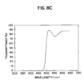
- Such filters may be provided having filter characteristics which provide a relatively low insertion loss to light having wavelengths less than 500 nanometers (nm). Filters having such fitter characteristics may be provided, for example, as one of the types manufactured by Corion corporation and identified as part number P70-450 or part number LS-500.
- filters may also be provided having filter characteristics which provide a relatively low insertion loss to light having wavelengths greater than 500 nanometers (nm).
- filters may be provided, for example, as the type manufactured by Corion corporation and identified as part number LL-500. Thus simultaneous emission of two distinct spectra may be separately detected by distinct, appropriately filtered PMT's.
- the filters should generally be provided having filter characteristics selected to minimize any spectral overlap in spectral transmittance . It is, however, most desirable to have a pair of chemiluminescent compounds with no spectral overlap in spectral transmittance to thus provide a system having a minimum amount of crosstalk, or to appropriately correct for spectral overlap.
- a reaction vessel 16 is disposed through the top region 12d of the housing 12 and extends into the chamber 13 such that opposite sides of the vessel 16 are exposed to a corresponding one of the photomultiplier tube assemblies 14a, 14b.
- the reaction vessel 16 may be provided for example as a cuvette or test tube or any other vessel well known to those of ordinary skill in the art.
- reagents which may be of the type described in commonly assigned co-pending patent application USSN 08/035.130, filed on even date herewith and incorporated herein by reference.
- the side wall regions 12b, 12d of the main housing 12 are provided having counterbores therethrough.
- An O-ring 18 is disposed at the bottom of each of the counter bores and the PMT assemblies 14a, 14b are disposed with a predetermined force in the counterbores against a corresponding one of the O-rings 18a, 18b such that the nosepiece 15a extends into the housing 12.
- the O-rings 18 prevent light from passing through the interface between the PMT assemblies 14a, 14b and the housing 12 and thus minimize the amount of external light provided to the chamber cavity 13.
- Each of the PMT assemblies 14a, 14b may be held in place by a corresponding clamp 20.
- Each of the clamps 20 are disposed and tightened about the circumference of a corresponding one of the PMT assemblies 14a, 14b.
- a top cover assembly 22 is disposed on the main housing 12 over a first end of the reaction vessel 16.
- the top cover assembly 22 is coupled to and aligns a probe assembly 28 in a predetermined location of the reaction vessel 16 and provides an opening through which the reaction vessel 16 may be inserted and removed from the main chamber 13.
- the probe assembly 28 will be described more fully below in conjunction with FIG. 2. Suffice it here to say that the top cover assembly 22 is connected to the probe assembly 28 and the probe assembly 28 may be disposed in the reaction vessel 16 to position at least one dispense probe 30 at a predetermined height above a final liquid height in the reaction vessel 16.
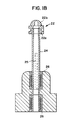
- the top cover assembly 22 (shown in Fig. 1 in the closed position and Fig. 1A in the open position) includes a cover body 22a and a cover plate 22b.
- the cover assembly 22 is connected to a shaft 24 (Fig. 1A) through a pin, and thus securely connects the cover assembly 22 to the shaft 24.
- the shaft 24 operates along two linear bearings 26 (Fig. 1 B), thus allowing the shaft 24 to move in both the radial and rotational directions.
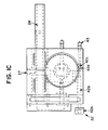
- the shaft 24 has here been provided having on a surface thereof an axial groove 25 having a predetermined length and a predetermined width. At one end of the shaft 24 the groove 25 rotates 90 degrees and follows a path in a direction along the circumference of the shaft 24 for a predetermined distance, here the distance corresponds to 90 degrees of rotation.
- a pin (not shown) may be connected to the main housing 12 at location 27 (FIG. 1C). The pin is disposed in the groove 25 to thus limit the mechanical travel of the shaft in an axial direction as determined by the groove length. The pin also limits the mechanical travel of the shaft 24 in a circumferential direction as determined by the circumferential length of the groove 25.
- the groove/pin combination provides the probe assembly 28 and top cover assembly 22 having a predetermined amount of movement selected such that the reaction vessel 16 may easily be inserted and removed from the chamber 13.
- the main housing 12 is here provided having a first surface with a groove therein, such groove being provided in a surface of the housing in a region and pattern which substantially circumscribes the reaction chamber 13.
- Acorresponding lip 23 may be provided in the top cover assembly 22, such that the lip 23 may be disposed in the groove to provide a region in which light may be trapped when the cover 22 is placed in its closed position.
- the assembly 22 provides a light tight seal against the main housing 12.
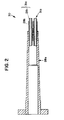
- the probe assembly 28 includes a probe body 28a which may preferably be lightly press fit into an opening of the top cover body 22a (FIG. 1) and held in place by the cover plate 22b (FIG. 1).
- the probe body 28a locates into a shouldered area of the top cover body 22c (FIG. 1) thus assuring proper orientation and positioning of the probes 30.
- the probe assembly 28 further includes a plurality of dispense probes 30.
- Each of the dispense probes 30 is provided from a guide tube 28b and a dispense tube 28c.
- the guide tube 28b may be provided, for example, as stainless steel tube press fit into the probe body 28a to secure the tube 28c in a predetermined location.
- the tube 28c provides a dispense port for acid and base solutions and thus may be provided from any dielectric material such as plastic, Teflon (TM) or any other dielectric or non-dielectric material well know to those of ordinary skill in the art.
- the tube 28c is provided having an outside diameter which is slightly larger than the inside diameter of the corresponding guide tube 28b, to provide a slight interference fit between tubes 28b and 28c to thus securely hold the tube 28c in the predetermined location.
- the system 10 further includes a reaction vessel sensor assembly 31 and a cover sensor assembly 32 which are coupled to the main housing 12 and operate to maintain the chamber 13 as a light-tight environment and to prevent damage to the PMT assemblies 14a, 14b during operation of the system 10.
- the reaction vessel sensor assembly 31 provides an indication to confirm that a vessel is disposed in the chamber 13.
- the reaction vessel sensor assembly 31 includes a sensor 34, a reaction vessel sensor flag 36, and a spring 38.
- the reaction vessel sensor flag 36 provides two functions.
- the first function is to assist in centrally locating the reaction vessel 16 in the chamber 13. It is desirable to centrally locate the reaction vessel 16 within the chamber 13 to provide an equal distance from each PMT 14, 14b to the corresponding side of the reaction vessel 16.
- the reaction vessel 16 may be centrally located, for example, by providing the reaction vessel sensor flag 36 having a first end in which a spherical socket is provided. The spherical radius of the socket may be selected to correspond to the spherical radius of a second end 16b of the reaction vessel 16.
- the second function of the flag 36 is to interrupt the sensor 34 when the reaction vessel 16 is inserted into the chamber 13 and the top cover 22 is properly closed.
- the flag 36 interrupts the sensor when the vessel 16 is properly located on the sensor flag 36.
- the sensor flag 36 is disposed over the spring 38 which exerts a spring force in the up direction on the vessel 16. This causes the reaction vessel 16 to protrude out of the main body 12.
- the top cover assembly 22 When the top cover assembly 22 is lowered onto the main body 12 the top cover assembly 22 exerts a force in the down direction upon the reaction vessel 16.
- the reaction vessel 16 forces the sensor flag 36 down against the spring force.
- the bottom of the sensor flag 36 is forced into the path of the optical sensor 34 and interrupts the optical path of the sensor. Consequently the optical sensor 34 provides a signal that the reaction vessel 16 is properly loaded into the chamber 13.
- the cover sensor assembly 32 is coupled to a spring loaded latch 40 disposed on the front of the housing 12 and senses whether the cover 22 is securely closed.
- the cover sensor 32 assembly includes a spring loaded flag activated by an optical switch when a vessel 16 is present in the chamber 13. When the sensor 32 is activated, a first LED will turn on. This sensor may help to prevent dispensing acid or base into the chamber when no vessel is present.
- the latch 40 is here implemented via a recess in the front of the housing in which a shaft 42 is disposed.
- the latch 40 provides two functions; first, it holds the top cover 22 in the closed position, thus pushing the vessel 16 down and activating the reaction vessel sensor 31 and second, the latch 40 provides a mechanism to activate the cover sensor 32 only after the cover 22 is in its closed position to provide a light tight seal.
- the cover sensor 32 may be coupled to the LED 42 and to an electrical logic circuit relay (not shown) which controls power to the PMT assemblies 14a, 14b.
- an electrical logic circuit relay not shown
- the sensors therefore, assist in preventing the PMT assemblies 14a, 14b from being exposed to excessive light.
- the sensor assemblies 31 and 32 protect the PMT assemblies 14a, 14b against inadvertent exposure to light while power is applied thereto. This reduces the settling time of the assemblies 14a, 14b.
- the cover sensor assembly 32 includes a knob 42c disposed over a first end of a cover sensor shaft 42b.
- the knob 42a may be secured to the cover sensor shaft 42b with, for example, a set screw or any other like means and provides an easy grip with which an operator may use the sensor assembly 32.
- a pair of ball bearings 42c having grooves of a predetermined depth provided in an outer surface thereof are coupled to a cover sensor swing shaft 42d.
- the cover sensor assembly 32 further includes an optical sensor 43 disposed about a second end of the cover sensor shaft 42b.
- the cover sensor shaft 42b is press fit into the cover sensor swing shaft 42d.
- the cover sensor swing shaft 42d may thus rotate about the axis of the cover sensor swing shaft 42d.
- the knob 42 prevents the cover 22 from being opened and exposing the cavity 13 and thus the reactor vessel 16 and powered up PMT assemblies 14a, 14b to ambient light. Furthermore, when the shaft 42b is engaged in a vertical position, the second end of the cover sensor shaft 42b interrupts the optical sensor 43, thus signaling that the top cover 22 is properly closed. When the sensor 43 is interrupted, power may be applied to the PMT assemblies 14a, 14b. When the cover sensor shaft 42b is rotated such that the knob 42a moves away from the cover 22, the knob 42a releases the top cover assembly 22, thus allowing the top cover assembly 22 to be opened.
- the optical sensor 43 is provided in an unblocked condition. That is, the optical sensor 43 does not detect any interruptions. When this occurs, power is removed from the PMT's 14a, 14b thus preventing operation of the system 10.
- LED 46a Disposed on the housing 12 are three light emitting diodes (LEDs) 46a, 46b and 46c, generally referred to as 46.
- LED 46a is coupled to the reaction vessel sensor 34.
- the LED 46c When the vessel 16 is disposed into the chamber 13 and the cover 22 is placed in its closed position, power is fed to the LED 46c and the LED 46c thus emits a light to indicate that the reaction vessel is in the chamber 13.
- the second LED 46b is coupled to the cover sensor 32.
- the spring loaded latch 40 When the spring loaded latch 40 is positioned in the vertical position, thus closing the latch 40, power is fed to the LED 46b which thus emits a light to thus indicate the cover 22 has been placed in its closed position.
- the LED 46c When both the reaction vessel and the cover sensor LED's 46a, 46b are activated, the LED 46c emits a light to thus indicate that the system 10 is properly prepared to perform a test.
- the vessel 16 should be removed from the chamber 13.
- a protection circuit prevents the system 10 from operating.
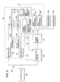
- a testing apparatus 48 includes a luminometer assembly 10,' which may be similar to the luminometer assembly 10 described above in conjunction with FIGS. 1-1C, and a protection circuit 49 which may be provided as a processor, an analog logic circuit, a digital logic circuit or by any other means well known to those of ordinary skill in the art.
- the protection circuit is coupled to a power supply 51 which provides power to the PMT assemblies 14a', 14b'.
- the protection circuit 49 is also coupled to sensors 32', 34' and prevents operation of the testing apparatus 48 unless predetermined conditions have been met.
- Each sensor 32', 34' provides a sensor signal (i.e. cover 22 opened and reaction vessel 16 removed from chamber 13) on a corresponding one of the signal paths 50, 51 to the protection circuit 49.
- the protection circuit 49 analyzes the sensor signals and provides a protection signal in response thereto. If the sensors 32', 34' indicate either that the cover 22 (FIG. 1A) has not been opened or that the vessel 16 (FIG. 1) has not been removed from the chamber 13 (FIG. 1) then the protection signal prevents operation of the system 10'. This is necessary to prevent fluid (e.g. a base fluid) from being twice added to a single vessel 16. The protection circuit may thus prevent two tests from being run in the same vessel 16.
- fluid e.g. a base fluid
- the testing apparatus 48 further includes a fluid injection system 50.
- the fluid injection system 50 may include a plurality of pumps, here two pumps 52, 54 being shown.
- each of the pumps may aspirate from a corresponding one of a like plurality of fluid containers 60, 62 for the first 180 degrees of rotation and will then dispense the aspirated fluid through a corresponding one of a like plurality of probes 64, 66 and into the reaction vessel 16 for the remaining 180 degrees of rotation.
- the pumps may aspirate fluid such as liquid acid and base solutions from respective ones of the containers 60, 62 and dispense the fluid through the probes 60, 62 (FIG. 1).
- the probes 60, 62 may be provided as uninterrupted tubes which allow the fluid to contact only the inside diameter of the tube with no transitions and only slight diametric variations.
- the probes 60, 62 may be coupled to like ones of the probes 30 (FIG. 1) which are preferably disposed such that the probes 30 provide fluid substantially into the center of the reaction vessel 16.
- the pumps 52, 54 may be provided as fixed stroke pumps which deliver on the order of 300 microliter (ul) of fluid per stroke.
- Such pumps may be provided, for example, as the type described in United States Patent 4,539,854 and EP-A-502 638, both assigned to the assignee of the present invention and incorporated herein by reference.
- any type of pump well known to those of ordinary skill in the art may also of course be used.
- Each of the pumps 52, 54 may be coupled to and driven by a corresponding motor 56, 57 which may be provided for example as a stepper motors.
- the speed at which the motors 56, 57 operates may be user programmable via a controller 68 and thus an operator may select an appropriate speed at which to operate each of the motors 56, 57 and consequently the pumps 52, 54.
- the controller may be provided for example as a processor and may also be used to provide a preselected time delay between the acid dispense and base dispense operations.
- the PMT assemblies 14a', 14b' are coupled to respective processors 70a, 70b which utilize the luminescence to provide constituent concentration information as is known in the art for single PMT systems.
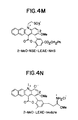
- FIGS. 4A-4N Representative compounds that may be reacted with a binding partner to form a conjugate or luminescent reagent and utilized in the practive of the present are shown in FIGS. 4A-4N.
- the following compound is utilized as a luminescent reagent: where W is carbon;
- the AFAC label can be reacted directly with the specific binding partner, ligand, or hapten either in an aqueous or an organic medium.
- chemiluminescent compound may have a coupling moiety to be reacted with a binding partner to form a conjugate.
- the chemi luminescent labels can include an appropriate leaving group or an electrophilic functional group attached with a leaving group or functional groups which can be readily converted into such reactive groups, directly attached or connected via a spacer for attaching a substance to form a conjugate to be utilized in a test assay.
- An example of preparing the LEAE-anti-TSH conjugate is provided below.
- a solution of a monoclonal anti-TSH antibody (2 mg, 0.013 umol) in 1.36 ml of 0.1 M phosphate buffer, pH 8.0 was treated with a solution of LEAE-NHS (43 ug, 0.067 umole) in 240 ul of acetonitrile at room temperature for one hour.
- the conjugation reaction was stopped by adding a solution of lysine (10 mg) in 0.5 ml of 0.1 M phosphate buffer, pH 8.
- the LEAE-conjugated anti-TSH was purified by passing the reaction mixture through a Sephadex G-25 column (1 x 20 cm) packed and eluted with 10 mM Phosphate, pH 8. The elution was monitored at 280 nm with a ISCO UV detector. The desired conjugate was collected when the first void volume peak was eluted out.
- the light emission spectra of LBAC's and the reference acridinium esters were determined by a Fast Spectral Scanning System (FSSS) of Photo Research (a division of Kollmorgen Corp) of Burbank, CA, U.S.A. The experiment was carried out in a dark room. Each sample was dissolved in HPLC grade acetonitrile at the concentration of 1 mg/ml or higher and diluted with the same solvent to obtain the sample solution in the concentration specified. A typical determination utilized 10 to 100 ug of each compound, with the exception of the angular benz[a]acridinium ester (2 mg), separately or mixed together in 0.5 ml acetonitrile contained in 13 x 100 mm borosilicate test tube.
- FSSS Fast Spectral Scanning System
- the tube was placed on a tube rack raised to a proper height.
- the FSSS optical head was placed in front of the tube at close distance and with its lense focused on the liquid in the tube.
- the sample solution was first treated with 0.35 ml of the Flashing Reagent#1 (Ciba Corning Diagnostics) containing 0.1 N HNO 3 and 0.1% H 2 0 2 .
- the room was then darkened, and 0.35 ml of the Flashing Reagent #2 (Ciba Corning Diagnostics) containing 0.25 N NaOH and 0.2% ARQUAD was added to the reaction mixture immediately, see U.S. Patent 4,927,769 which is commonly assigned and incorporated herein by reference.
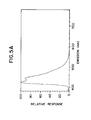
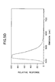
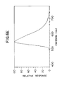
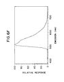
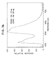
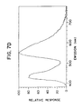
- FIGS. 5 A-5E, 6A-6J, and 7A-7D Recorded emission spectra are shown in FIGS. 5 A-5E, 6A-6J, and 7A-7D.
- FIGS. 5A-5E and 6A-6J show individual emission spectra of chemiluminiscent compounds including an acridinium ring system and compounds including a benzacridinium ring system. The difference of the emission maxima between acridinium esters and LBAC's were found to range between 80-128 nm, while that between acridinium esters and the ABAC was about 8-14 nm. As shown in FIGS.
- LBAC's, ABAC, and DMAE-Bz were determined on a Berthold luminometer (MLA-I) (Ciba Corning Diagnostics Corp.) fitted with a BG-38 filterwith wavelength transmission range of about 320 to 650 nm at transmission efficiency of 20 to 97%. (FIG. 5, Panel A). Alternate filters may be incorporated in luminometers to expand the range of transmission efficiency.
- Each sample was prepared in acetonitrile solution at 1 mg/ml, serially diluted to 10 ug/ml in acetonitrile and further on to 1 ng/ml, 0.1 ng/ml and 0.01 ng/ml in 10 mM phosphate buffer iwht 0.15 M NaCI, 0.1% BSA. 0.05% NaN 3 , pH8.
- the light emitting efficiency of the LBAC's was comparable to that of DMAE-Bz within the range of 0.21 to 1.39 fold, depending on the substitutents on the benzacridinium nucleus and the phenoxy group. It should be noted these determinations were based on 2-second signal collection and have not taken into account the flashing kinetics of the individual compounds, e.g. some compounds may take greater thatn 2 seconds to release most of their signals, the sensitivity of the photomultiplying tube, and the transmission efficiency of the optical filter(s) at different points of the spectral range. These findings, however, were totally unexpected in view of the much lower light emitting efficiency of the isomeric ABAC. This level of light emitting efficiency renders LEAC's useful in sensitive binding assays, including multi-analyte assays.
- DMAE and LEAE in the form of protein conjugates also demonstrated no mutual interactions in their light emissions during flashing as shown by no decrease or increase of the combined Relative Light Units (RLU) registered.
- RLU Relative Light Unit
- the results in Table IV show that the two tracers of different emission spectra were absolutely non-interfering between each other in their light emission. This characteristic further ensures their utility in multi- analyte binding assays.
- the LEAE of the preferred method is a N-alkylated benzacridinium compound.
- LBAC-Anti-TSH conjugates were prepared and tested for their stability in aqueous media. DMAE-anti-TSH conjugate was also tested side by side. The retention of chemi luminescent activity as a function of temperature at various pH's (using citrate-phosphate buffer containing 0.1 % BSA) was monitored over 7 day period. Proper concentrations of the above conjugates (0.8 - 1.4 x 10 6 RLU's/25 ul) were placed in two sets of different buffers (pH 7.4, 8.0, 8.5, and 9.0). One set was kept at 4-8°C as a control, while the other was subjected to 37°C. The buffered samples (25 ul) were flashed periodically as described above. The results are summarized in Table V.
- LEAE-anti-TSH was employed as tracer in a TSH assay. Performance was assessed by determining signal-to-noise (S/N) ratio. The performance of DMAE-antiTSH was also compared side by side.
- the assay was configured as follows:
- Awash was done first by magnetically separating the particles from the solution, decanting the solution, then adding 500 ul of water, followed by another magnetic separation. The washed particles were resuspended in 100 ul of water. Flashing and counting were done according to the above-described procedures. The results are provided in Table VI using ratios of the counts with a TSH standard containing TSH versus the zero TSH standard.
- Dual-PMT Luminometer utilized to demonstrate the hardware of DPL includes at least two photo multiplyer tube (PMT) assemblies, an injection pump for Flashing Reagent #2, and a cube- shape light tight chamber designed for holding a disposable cuvette.
- PMT photo multiplyer tube
- injection pump for Flashing Reagent #2 an injection pump for Flashing Reagent #2
- cube- shape light tight chamber designed for holding a disposable cuvette.
- the top of the cuvette- holding chamber is hinged to allow the cuvette to be manually inserted and removed.
- the top also has a fixed probe attached for the purpose of injecting the Flashing Reagent #2 into the cuvette.
- Within each PMT assembly an optical filter selected for particular spectral range, and is inserted between the cuvette and the PMT tube.
- DPLs may be designed for semi-automated and automated detection of two or more chemiluminescent compounds or conjugates in a test sample.
- a luminometer as a component on an automated analyzer is described in EP-A-0 502 638 noted above.
- Essential to the discrimination or discernability of two or more emitted light spectra are the choices of a plurality of optical filters with proper wavelength cutoffs.
- Filters of this type are widely available from commercial vendors and may be modified, i.e. by lamination or specifically manufactured to be incorporated in a PMT assembly for detection and/or quantitation of spectral signals of the conjugates. Careful selection of filters will enhance the ability to discern emission signals and with appropriate correction may allow multiple signals with the emission overlap to be discerned.
- a long pass filter P/N LL-500 of Corion, Holliston, MA
- a short pass filter P/N P70-450 also of Corion
- Optical filters with more desirable transmittance profile and cut-off may be selected to maximize the transmission of light emitted from the tracers and/or to fit better with the emission spectral ranges of particular chemiluminescent compounds so as to improve the Percent Cross Talk (PCT) as described below.
- PCT Percent Cross Talk
- Corion's laminated CS550/CS600 filter (FIG. 5, panel D) was found to be a better replacement for filter P70-450 as the short pass filter matching with the long pass filter LL-500 for the determination of the pair of DMAE and LEAE tracers.
- a personal computer unit containing proper software is utilized and connected to the DPL.
- the two optical filters installed in two separate PMT assemblies on the DPL were intended to gate the emitted lights of two different spectral ranges: the long pass filter is to match with the longer emission from LEAE tracer and the short pass filter with the shorter emission from DMAE tracer.
- the long pass filter is to match with the longer emission from LEAE tracer and the short pass filter with the shorter emission from DMAE tracer.
- FIGS. 6 and 7 because of the minor overlap between the transmittance curves and the emission spectra of the cross-matching pairs, light signals generated by one tracer can be picked up by the primary PMT intended for it but also in small percentage by the secondary PMT intended for the other tracer, and vice versa.
- Table VIl shows the determined PCT's of several pairs of tracers.
- Anti-FSH-DMAE and anti-LH-LEAE were used in the simultaneous LH/FSH dual-analyte assay described below.
- Other pairs of tracers were included to demonstrate that through the selection of acridinium and benzacridinium compounds of wider separation in their emission maxima and proper choice of optical filters, minimal PCT's ideal for multi-analyte assay can be realized.
- the PCT's were obtained by dividing the minor signal from the secondary PMT by the major signal from the primary PMT in each .case, and multiplying the results by 100%.
- the concentrations of the samples were randomly selected such that the primary signals fell in the range of 100,000 to 1,500,000 RLU's per 25 ul sample. Each determination was made by sequencially pipeting 25 ul of one tracer solution, 300 ul of Flashing Reagent #1 into the cuvette, vortexing the resulting solution briefly, inserting the cuvette into the PMT housing, and performing the flashing by injecting 300 ul of Flashing Reagent #2 through the key-board control.
- S(s) and S(I) are the observed short and long pass signals, respectively;
- S(DMAE) and S(LEAE) are the portions of signals due to DMAE and LEAE in the observed short and long pass signals, respectively. They will also be referred to as the corrected DMAE and LEAE signals;
- S'(DMAE) and S'(LEAE) are portions of the long and short pass signals due to DMAE and LEAE cross-talking, respectively;
- b1 and b2 are the combined signals due to assay components and system noise in the absence of DMAE and LEAE tracers, respectively.
- Equations (5) and (6) will yield the corrected.short pass signal due to DMAE tracer and long pass signal due to LEAE tracer, respectively.
- the determination of the combined matrix and system noises, b1 and b2 was found not to be significant. They were therefore both assigned a 0 value in the signal corrections for the following examples of the dual-analyte assays.
- LH Luteinizing Hormone
- FSH Follicle Stimulating Hormone
- One objective of the invention is to provide a method for simultaneously detecting and/or quantitating two or more substances or analytes in a single sample through the utilization of two different chemiluminescent labels or conjugates.
- the assay system utilizes a DMAE labelled FSH antibody and a LEAE labelled LH antibody.
- the following examples demonstrate that LH and FSH standard curves and sample recovery are identical within the limits of experimental error when each analyte is assayed as a single analyte by introduction of one chemiluminescent tracer into the assay system, or in a dual analyte system which employs two chemi luminescent tracers.
- the examples further show that tracers prepared from a pair of a DMAE and a LEAC can be utilized in a simultaneous assay of two substances for which a corresponding binding partner, e.g. antibody, is available.
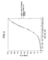
- the Magic Lite FSH kit components and protocol were modified such that the assay could be performed as a single or dual analyte assay depending on the tracer selection.
- a solid phase consisting of paramagnetic particles (PMP) coupled to anti-FSH antibodies and PMP coupled to anti-LH antibodies was prepared by removing the buffer diluent from the Magic Lite FSH kit solid phase and resuspending these particles in Magic Lite LH kit solid phase (Ciba Corning Diagnostics Corp.).
- the kit tracer, anti-FSH-DMAE was diluted 1:2 in Magic Lite LH kit tracer buffer. Standards for calibration contained both FSH and LH.
- Example 15 The solid phase reagent, standards, and samples described in Example 15 were used to perform an LH assay.
- the anti-FSH-DMAE tracer was replaced with an anti-LH-LEAE tracer which was diluted 1:2 in Magic Lite FSH kit tracer diluent.
- the assay methodology described in Example 13 was applied to this assay, except that the RLU results obtained from the Long pass (LEAE) channel were used to calculate LH sample concentrations.
- the assay was calibrated using nine of the standards described in Example 15, excluding the 1.0 mlu/ml LH standard. Results for this assay are shown in Table XI and Table XII under the heading LH single-analyte assay. The standard curve is shown in Figure 9 labelled as LH single-analyte assay.
- Example 15 and 16 Solid phase reagent, standards, and samples described in Example 15 and 16 were used to perform a dual label LH/FSH assay in a single tube.
- the tracer consisted of the Magic Lite FSH kit tracer, anti-FSH-DMAE diluted 1:2 in the anti-LH-LEAE tracer.
- the assay methodology was the same as that described in Example 15.
- the raw RLU's from each channel was mathematically corrected for cross-talk prior to concentration calculations. Corrected RLU's and concentrations resulting from these corrected RLU's are shown in Tables IX-XII, and are labelled as dual-analyte assay. Mean sample recovery for single analyte vs.
- the present invention relates to chemiluminescent compounds and more particularly, the use of two or more chemiluminescent conjugates to simultaneously detect two or more substances in a test sample.
- the disclosure teaches the use of benzacridinium compounds and preferably N-alkylated benzacridinium compounds in such assays.
- a test substance includes any component(s) or analytes sought to be detected and/or quantitated in a test sample, including but not limited to, more than one component of a single structure, e.g. more than one portion of a nucleic acid sequence or different loci of a chromosome, genome or molecule, where the components or analytes may be of biological or industrial origin, such as nucleic acids, proteins, ligands, haptens or other materials or compounds to which an appropriate assay method can be formatted. It is understood that the test sample and/or substance may need to be pretreated to render it assayable by a test method.
- test substances and quantities thereof sought to be detected may limit the types of assays which can be performed because of, for example, sensitivity concerns, but not the use of chemi luminescent labels for detection.
- Various internal standards or controls may be added to a test sample for detection and/or quantitation to asess the performance of the assay.
- Diagnostic assays exemplified by immunoassays, hybridization assays and amplification assays have increasingly incorporated chemiluminescent labels in their formats. Designs and formats of such assays are well known by those skilled in the art and extensively published in the technical and patent literature, for example, an assay format may require the seperation of a reaction product or unreacted agent to a transfer tube for detection and/or quantitation. Such separation techniques may be useful for competitive assays, solid phase assays or to limit interferents.
- two or more chemiluminescent conjugates are utilized as labels in an amplification assay.
- Representative amplification assays include but should not be limited to polymerase chain reaction (PCR), autocatalytic replication of recombinant RNA and amplification of midivariant DNA or RNA. See EP-A- 481 704.
- Such methods may be made adaptable to incorporate chemiluminescent labels, and particularly two or more chemi luminescent labels for detection of target sequences of interest.
- the advantage of using a multi-label method is to detect and/or quantitate a plurality of target sequences or one or more target sequences and an internal standard.
- An example of such a method includes providing a test sample suspected of containing one or more target sequences, amplifying the target sequences, providing at least two chemiluminescent conjugates, each chemiluminescent conjugate being associated with a target sequence(s) and simultaneously detecting and/or quantifying amplified target sequences by emissions of at least two chemiluminescent conjugates.
- an internal reference, control or control system may be added to the assay to insure assay performance and results.
- the internal reference may be amplified as well as the target sequences.
- the chemiluminescent compounds of this invention are adapted to be packaged in kit form for commercial sale.
- the chemiluminescent labels of these kits may be conjugated to appropriate substances or materials which are specific to the substances sought to be detected in the test samples. Appropriate functional groups may be added to the chemiluminescent compounds for use in various assays and other applications.
- assays for which the methods of the present invention may be utilized include but should not be limited to: assays including at least two antibodies of different specifities; assays including at least two antigens; assays including at least one antigen and at least one antibody; and assays for molecules indicative of cancer, infectious diseases, genetic abnormalities, genetic disposition, genetic assessment and to monitor medicinal therapy.
Abstract
A method and apparatus for determining a plurality of substances or constituents of a specimen sample includes the steps of placing a single specimen sample in a reaction vessel or test tube and adding at least two reagents to the reaction vessel to form a detectable product and then initiating a reaction within the vessel and provide an emission of light energy in a predetermined spectral range. The reaction vessel is disposed in a chamber of a housing and a plurality of detector assemblies are disposed about the housing with portions of the detector assemblies disposed through the housing and exposed to the reaction vessel. Each of the detector assemblies receives a portion of the light emission and feeds such portion to a detector. Each of the detectors detect the existence of light emissions in one of a plurality of spectral ranges and feeds that information to processing circuitry to provide data for determining the presence of a specific specimen substance(s) or constituent(s) based upon the detected luminescence.
Description
- This invention relates to specimen testing apparatus and more particularly to luminometers.
- As is known in the art, systems which may be used to test specimen samples such as blood samples, for example, add a single reagent to the sample in a chamber. The reagent reacts with the sample and cause the sample to emit light or to form a detectable product which, on further treatment, will emit light. Depending upon the presence of the constituent(s) of the sample a corresponding spectral distribution of the emitted light is provided. Furthermore, depending upon the specimen sample and the reagent added thereto the resultant luminescence occurs in a predetermined spectral range. The light emissions may be fed through a spectral filter and subsequently coupled to a photomultiplier tube and detector. Thus, with knowledge of the type of specimen sample, the type of reagent and the resultant spectral representation it is possible to determine the presence of certain substances in the specimen sample. Separate tests may be run with different reagents in the separate chambers to test for other constituents in the specimen.
- It may in some applications, however, be desirable to provide a system in which a plurality of reagents may be added to a single chamber and a detection system simultaneously detects light emission in a plurality of different spectral ranges. Thus according to the present invention, specimen analysis is enhanced by applying at least two reagents to the same specimen sample in a specially adapted chamber and using a plurality of detectors to simultaneously detect the chemiluminescence in separate spectral ranges caused by the reaction with one or more substances of the specimen. The reagents react with the sample substances and are further treated to provide substantially non-overlapping luminescence signals which may be sensed by the detectors and separately processed to determine the constituents or substances of the specimen sample.
- Thus in accordance with the present invention, a testing apparatus includes a housing having a chamber. A reaction vessel is disposed through a bore in a top wall region of the housing and retained in a predetermined location in the chamber. A plurality of detector assemblies are disposed about the housing with each one of such detector assemblies disposed through a corresponding bore provided in corresponding side wall regions of the housing such that the reaction vessel is exposed to the detector assemblies. In accordance with this particular arrangement, a luminometer capable of detecting one or more substances of a specimen sample having a resultant luminescence in a plurality of separate spectral ranges is provided. The reaction vessel may be provided, for example, as a cuvette or a test tube. Into the reaction vessel may be added a specimen sample and a plurality of luminescent reagents or conjugates reagents. The reagents are selected such that they interact with the sample but not with each other. The reagents react with the sample to provide, from the sample, a product which, upon further treatment, results in light emissions in a plurality of different spectral ranges. The detector assemblies may include, for example, photomultiplier tubes (PMTs). Each of the plurality of PMTs may provide a response to a chemiluminescent flash produced in the reaction vessel. A first one of the PMTs may respond to light emissions in a first spectral range and a second one of the plurality of PMTs may substantially simultaneously respond to light emissions in a second spectral range. Thus, the luminometer may detect, in a single test, light emissions in at least two different spectral ranges. The testing apparatus may also be provided having a fluid injection system coupled to the housing through a dispense tube to thus provide the testing apparatus having fluid control capabilities. The fluid injection system may be used to add acid and/or base fluid to the reaction vessel. Thus, vessels which are prepared to have acid and/or base fluids added thereto may be disposed in the housing and the fluid injection system may be used to add the requisite type and amount of fluid to the reaction vessel. Furthermore a processor may be coupled to the fluid injection system to control the timing and amount of fluid introduced into the reaction vessel via the fluid injection system. Moreover, the processor may also control the timing with which tests are conducted in the testing apparatus.
- The testing apparatus may also be provided with an automated means for advancing vessels to the detector assemblies and following the luminescent flash, removal from the apparatus.
- The foregoing features of this invention as well as the invention itself may be more fully understood from the following detailed description of the drawings in which:
- FIG. 1 is a top view of a luminometer assembly;
- FIG. 1A is a cross sectional view of the luminometer assembly taken along lines 1A-1A of FIG. 1;
- FIG. 1 B is a cross sectional view of the luminometer assembly taken along lines 1 B-1 B of FIG. 1;
- FIG. 1C is a side view of the luminometer assembly taken along lines 1 C-1 C of FIG. 1;
- FIG. 2 is a partial cross sectional view of a probe assembly which may be of the type used in the luminometer of FIG. 1; and
- FIG. 3 is a block diagram of a luminometer assembly having a fluid injection system.
- FIGS. 4A-4N illustrate the structures of representative acridinium esters, ABAC, and LBAC's.
- FIGS. 5A-5E illustrate emission spectra of acridinium esters and ABAC.
- FIGS. 6A-6J illustrate emission spectra of LBAC.
- FIGS. 7A-7D illustrate emission spectra of mixed acridinium esters and LBAC.
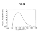
- FIGS. 8A-8E illustrate transmittance curves. of various optical filters.
- FIG. 9 illustrates the area of overlap between the transmittance curve of an optical filter (Corion LL500) and the emission spectra of DMAE-Bz.
- FIG. 10 illustrates the area of overlap between the transmittance curve of an optical filter (Corion P70-450) and the emission spectra of LEAE-Bz.
- FIG. 11 illustrates FSH standard curve assays read on a dual PMT luminometer.
- FIG. 12 illustrates LH standard curve assays read on a dual PMT luminometer.
- Referring now to FIGS. 1 - 1C in which like elements are provided having like reference designations throughout the several views, a
luminometer assembly 10 includes amain housing 12 having abase region 12a,side wall regions top region 12f. The base, side wall and top regions are provided having continuous portions such that thehousing 12 provides achamber 13 in which a reaction may take place. A plurality of photomultiplier tube assemblies may be disposed in the sidewall regions of thehousing 12, a pair of suchphotomultiplier tube assemblies side wall regions housing 12. - Each of the
photomultiplier tube assemblies aluminum housing 15 in which may be disposed a conventional photo-multiplier tube and a conventional amplifier/discriminator board. The photomultiplier tubes (PMTs) may be provided as, but are not limited to, the types having side-on photocathodes, end-on photocathodes or a combination of both side-on and end-on photocathodes. Suffice it to say that PMTs disposed in thephotomultiplier tube assemblies - The
aluminum housing 15 includes anosepiece 15a having aquartz window 15b disposed therein. Alternatively, thenosepiece 15a may be provided having a filter (not shown) disposed therein in addition to or in place of the quartz window to thus optimize the performance of the corresponding PMT assembly. Such filters may preferably be disposed between the photocathode and the reaction vessel and such filters may preferably be provided having filter characteristics which selectively allow chemiluminescent emissions in predetermined spectral ranges to pass therethrough. Thus the filters may preferably be provided having bandpass filter characteristics. However, the f i lters may alternatively be provided having lowpass, highpass, stopband, or any other filter characteristics well known to those of ordinary skill in the art. - Such filters may be provided having filter characteristics which provide a relatively low insertion loss to light having wavelengths less than 500 nanometers (nm). Filters having such fitter characteristics may be provided, for example, as one of the types manufactured by Corion corporation and identified as part number P70-450 or part number LS-500.
- Alternatively such filters may also be provided having filter characteristics which provide a relatively low insertion loss to light having wavelengths greater than 500 nanometers (nm). Such filters may be provided, for example, as the type manufactured by Corion corporation and identified as part number LL-500. Thus simultaneous emission of two distinct spectra may be separately detected by distinct, appropriately filtered PMT's.
- Since spectral transmittance overlap is a source of "crosstalk" between the detectors and corresponding chemiluminescent compounds, the filters should generally be provided having filter characteristics selected to minimize any spectral overlap in spectral transmittance . It is, however, most desirable to have a pair of chemiluminescent compounds with no spectral overlap in spectral transmittance to thus provide a system having a minimum amount of crosstalk, or to appropriately correct for spectral overlap.
- A
reaction vessel 16 is disposed through thetop region 12d of thehousing 12 and extends into thechamber 13 such that opposite sides of thevessel 16 are exposed to a corresponding one of thephotomultiplier tube assemblies reaction vessel 16 may be provided for example as a cuvette or test tube or any other vessel well known to those of ordinary skill in the art. Into thereaction vessel 16 will be added reagents which may be of the type described in commonly assigned co-pending patent application USSN 08/035.130, filed on even date herewith and incorporated herein by reference. - The
side wall regions main housing 12 are provided having counterbores therethrough. An O-ring 18 is disposed at the bottom of each of the counter bores and thePMT assemblies nosepiece 15a extends into thehousing 12. The O-rings 18 prevent light from passing through the interface between thePMT assemblies housing 12 and thus minimize the amount of external light provided to thechamber cavity 13. Each of thePMT assemblies clamp 20. Each of theclamps 20 are disposed and tightened about the circumference of a corresponding one of thePMT assemblies - A
top cover assembly 22 is disposed on themain housing 12 over a first end of thereaction vessel 16. Thetop cover assembly 22 is coupled to and aligns aprobe assembly 28 in a predetermined location of thereaction vessel 16 and provides an opening through which thereaction vessel 16 may be inserted and removed from themain chamber 13. - The
probe assembly 28 will be described more fully below in conjunction with FIG. 2. Suffice it here to say that thetop cover assembly 22 is connected to theprobe assembly 28 and theprobe assembly 28 may be disposed in thereaction vessel 16 to position at least one dispenseprobe 30 at a predetermined height above a final liquid height in thereaction vessel 16. - The top cover assembly 22 (shown in Fig. 1 in the closed position and Fig. 1A in the open position) includes a
cover body 22a and acover plate 22b. Thecover assembly 22 is connected to a shaft 24 (Fig. 1A) through a pin, and thus securely connects thecover assembly 22 to theshaft 24. Theshaft 24 operates along two linear bearings 26 (Fig. 1 B), thus allowing theshaft 24 to move in both the radial and rotational directions. - The
shaft 24 has here been provided having on a surface thereof anaxial groove 25 having a predetermined length and a predetermined width. At one end of theshaft 24 thegroove 25 rotates 90 degrees and follows a path in a direction along the circumference of theshaft 24 for a predetermined distance, here the distance corresponds to 90 degrees of rotation. A pin (not shown) may be connected to themain housing 12 at location 27 (FIG. 1C). The pin is disposed in thegroove 25 to thus limit the mechanical travel of the shaft in an axial direction as determined by the groove length. The pin also limits the mechanical travel of theshaft 24 in a circumferential direction as determined by the circumferential length of thegroove 25. Thus the groove/pin combination provides theprobe assembly 28 andtop cover assembly 22 having a predetermined amount of movement selected such that thereaction vessel 16 may easily be inserted and removed from thechamber 13. - To reduce measurement errors, it is desirable to shield the reaction and thus the reaction vessel from ambient light. It is thus desirable to provide the
chamber 13 as a lighttight chamber 13. - To provide a light seal between the
top cover 22 and themain housing 12, themain housing 12 is here provided having a first surface with a groove therein, such groove being provided in a surface of the housing in a region and pattern which substantially circumscribes thereaction chamber 13.Acorresponding lip 23 may be provided in thetop cover assembly 22, such that thelip 23 may be disposed in the groove to provide a region in which light may be trapped when thecover 22 is placed in its closed position. When thetop cover assembly 22 is placed in its closed position, theassembly 22 provides a light tight seal against themain housing 12. When thePMT assemblies rings 18 and thetop cover assembly 22 is disposed on thehousing 12 and placed in its closed position, light is prevented from entering thechamber 13 and thechamber 13 is thus provided as a light tight chamber. - Referring briefly to FIG. 2, the
probe assembly 28 includes a probe body 28a which may preferably be lightly press fit into an opening of thetop cover body 22a (FIG. 1) and held in place by thecover plate 22b (FIG. 1). The probe body 28a locates into a shouldered area of the top cover body 22c (FIG. 1) thus assuring proper orientation and positioning of theprobes 30. - Portions of the probe body 28a have here been removed to reveal that the
probe assembly 28 further includes a plurality of dispense probes 30. Each of the dispense probes 30 is provided from aguide tube 28b and a dispensetube 28c. Theguide tube 28b may be provided, for example, as stainless steel tube press fit into the probe body 28a to secure thetube 28c in a predetermined location. Thetube 28c provides a dispense port for acid and base solutions and thus may be provided from any dielectric material such as plastic, Teflon (TM) or any other dielectric or non-dielectric material well know to those of ordinary skill in the art. Thetube 28c is provided having an outside diameter which is slightly larger than the inside diameter of thecorresponding guide tube 28b, to provide a slight interference fit betweentubes tube 28c in the predetermined location. - Referring again to FIGS. 1 - 1 C, the
system 10 further includes a reactionvessel sensor assembly 31 and acover sensor assembly 32 which are coupled to themain housing 12 and operate to maintain thechamber 13 as a light-tight environment and to prevent damage to thePMT assemblies system 10. - The reaction
vessel sensor assembly 31 provides an indication to confirm that a vessel is disposed in thechamber 13. The reactionvessel sensor assembly 31 includes asensor 34, a reactionvessel sensor flag 36, and aspring 38. The reactionvessel sensor flag 36 provides two functions. - The first function is to assist in centrally locating the
reaction vessel 16 in thechamber 13. It is desirable to centrally locate thereaction vessel 16 within thechamber 13 to provide an equal distance from eachPMT 14, 14b to the corresponding side of thereaction vessel 16. Thereaction vessel 16 may be centrally located, for example, by providing the reactionvessel sensor flag 36 having a first end in which a spherical socket is provided. The spherical radius of the socket may be selected to correspond to the spherical radius of asecond end 16b of thereaction vessel 16. - The second function of the
flag 36 is to interrupt thesensor 34 when thereaction vessel 16 is inserted into thechamber 13 and thetop cover 22 is properly closed. Theflag 36 interrupts the sensor when thevessel 16 is properly located on thesensor flag 36. Thesensor flag 36 is disposed over thespring 38 which exerts a spring force in the up direction on thevessel 16. This causes thereaction vessel 16 to protrude out of themain body 12. When thetop cover assembly 22 is lowered onto themain body 12 thetop cover assembly 22 exerts a force in the down direction upon thereaction vessel 16. Likewise, thereaction vessel 16 forces thesensor flag 36 down against the spring force. The bottom of thesensor flag 36 is forced into the path of theoptical sensor 34 and interrupts the optical path of the sensor. Consequently theoptical sensor 34 provides a signal that thereaction vessel 16 is properly loaded into thechamber 13. - The
cover sensor assembly 32 is coupled to a spring loadedlatch 40 disposed on the front of thehousing 12 and senses whether thecover 22 is securely closed. Thecover sensor 32 assembly includes a spring loaded flag activated by an optical switch when avessel 16 is present in thechamber 13. When thesensor 32 is activated, a first LED will turn on. This sensor may help to prevent dispensing acid or base into the chamber when no vessel is present. - The
latch 40 is here implemented via a recess in the front of the housing in which a shaft 42 is disposed. Thelatch 40 provides two functions; first, it holds thetop cover 22 in the closed position, thus pushing thevessel 16 down and activating thereaction vessel sensor 31 and second, thelatch 40 provides a mechanism to activate thecover sensor 32 only after thecover 22 is in its closed position to provide a light tight seal. Thecover sensor 32 may be coupled to the LED 42 and to an electrical logic circuit relay (not shown) which controls power to thePMT assemblies sensor 32 is placed in its open position, no voltage is provided to thePMT assemblies PMT assemblies sensor assemblies PMT assemblies assemblies - The
cover sensor assembly 32 includes aknob 42c disposed over a first end of acover sensor shaft 42b. Theknob 42a may be secured to thecover sensor shaft 42b with, for example, a set screw or any other like means and provides an easy grip with which an operator may use thesensor assembly 32. A pair ofball bearings 42c having grooves of a predetermined depth provided in an outer surface thereof are coupled to a coversensor swing shaft 42d. Thecover sensor assembly 32 further includes anoptical sensor 43 disposed about a second end of thecover sensor shaft 42b. Thecover sensor shaft 42b is press fit into the coversensor swing shaft 42d. The coversensor swing shaft 42d may thus rotate about the axis of the coversensor swing shaft 42d. - As may be most clearly seen in FIG. 1C when the
cover sensor shaft 42b is placed in a vertical position (that is having a longitudinal axis parallel to the longitudinal axis of probe 30), the knob 42 prevents thecover 22 from being opened and exposing thecavity 13 and thus thereactor vessel 16 and powered upPMT assemblies shaft 42b is engaged in a vertical position, the second end of thecover sensor shaft 42b interrupts theoptical sensor 43, thus signaling that thetop cover 22 is properly closed. When thesensor 43 is interrupted, power may be applied to thePMT assemblies cover sensor shaft 42b is rotated such that theknob 42a moves away from thecover 22, theknob 42a releases thetop cover assembly 22, thus allowing thetop cover assembly 22 to be opened. - Once the
cover sensor shaft 42b andknob 42a have moved a distance such that theshaft 42b has sufficiently cleared thetop cover assembly 22, theoptical sensor 43 is provided in an unblocked condition. That is, theoptical sensor 43 does not detect any interruptions. When this occurs, power is removed from the PMT's 14a, 14b thus preventing operation of thesystem 10. - Disposed on the
housing 12 are three light emitting diodes (LEDs) 46a, 46b and 46c, generally referred to as 46. LED 46a is coupled to thereaction vessel sensor 34. Thus when thevessel 16 is disposed into thechamber 13 and thecover 22 is placed in its closed position, power is fed to the LED 46c and the LED 46c thus emits a light to indicate that the reaction vessel is in thechamber 13. - The second LED 46b is coupled to the
cover sensor 32. When the spring loadedlatch 40 is positioned in the vertical position, thus closing thelatch 40, power is fed to the LED 46b which thus emits a light to thus indicate thecover 22 has been placed in its closed position. - When both the reaction vessel and the cover sensor LED's 46a, 46b are activated, the LED 46c emits a light to thus indicate that the
system 10 is properly prepared to perform a test. - As will be described further below in conjunction with FIG. 3, once a test has been completed, the
vessel 16 should be removed from thechamber 13. Upon completion of a test, if thecover 22 has not been opened and or thevessel 16 has not been removed from thechamber 13, a protection circuit prevents thesystem 10 from operating. - Referring now to FIG. 3, a
testing apparatus 48 includes aluminometer assembly 10,' which may be similar to theluminometer assembly 10 described above in conjunction with FIGS. 1-1C, and aprotection circuit 49 which may be provided as a processor, an analog logic circuit, a digital logic circuit or by any other means well known to those of ordinary skill in the art. The protection circuit is coupled to apower supply 51 which provides power to thePMT assemblies 14a', 14b'. Theprotection circuit 49 is also coupled to sensors 32', 34' and prevents operation of thetesting apparatus 48 unless predetermined conditions have been met. - Each sensor 32', 34' provides a sensor signal (i.e.
cover 22 opened andreaction vessel 16 removed from chamber 13) on a corresponding one of thesignal paths protection circuit 49. To test for the requisite conditions, theprotection circuit 49 analyzes the sensor signals and provides a protection signal in response thereto. If the sensors 32', 34' indicate either that the cover 22 (FIG. 1A) has not been opened or that the vessel 16 (FIG. 1) has not been removed from the chamber 13 (FIG. 1) then the protection signal prevents operation of the system 10'. This is necessary to prevent fluid (e.g. a base fluid) from being twice added to asingle vessel 16. The protection circuit may thus prevent two tests from being run in thesame vessel 16. - The
testing apparatus 48 further includes afluid injection system 50. Thefluid injection system 50 may include a plurality of pumps, here twopumps fluid containers probes reaction vessel 16 for the remaining 180 degrees of rotation. The pumps may aspirate fluid such as liquid acid and base solutions from respective ones of thecontainers probes 60, 62 (FIG. 1). Theprobes probes probes 30 provide fluid substantially into the center of thereaction vessel 16. - The
pumps - Each of the
pumps motor motors controller 68 and thus an operator may select an appropriate speed at which to operate each of themotors pumps - The
PMT assemblies 14a', 14b' are coupled torespective processors - Representative compounds that may be reacted with a binding partner to form a conjugate or luminescent reagent and utilized in the practive of the present are shown in FIGS. 4A-4N.
- The following abreviations are utilized in the disclosure:

- In one embodiment of the invention, the following compound is utilized as a luminescent reagent:

where W is carbon; - alternatively, C7, W, C9 or C10 can be -N=;
- or W can be omitted and C7 connected to Cg, and C7, C9 of C10, can be -O-, -S-, -NH-, or -NR-;
- Y includes a branched or straight chained alkyl containing optionally up to 20 carbon atoms, halogenated or unhalogenated, or a polysubstituted aryl moiety of the formula:

R1 includes alkyl, alkenyl, alkynyl or aralkyl containing optionally up to 20 heteroatoms; - R2, R3, R9 and R10 are identical or different groups selected from hydrogen, substituted or unsubstituted aryl (ArR or Ar), halide, amino, hydroxyl, nitro, sulfonate, -R -CN, -COOH, -SCN, -R, -OR, -SR, -SSR, -C(O)R, -C(O)OR, -C(O)NHR, or NHC(O)R;
- R2 includes a single or multiple substituent at C1-4;
- R3 includes a single or multiple substituent at C7, W, Cg or C10;
- R2 can also be a fused aromatic ring with or without heteroatoms;
- A- is a counter ion;
- X is a heteroatom including nitrogen, oxygen or sulfur, such that when X is oxygen or sulfur Z is omitted, when X is nitrogen then Z is -S02-Y', and Y' is equal to Y and where the substituents to Y and Y' do not have to be the same,
- R4 and R8 include alkyl, alkenyl, alkynyl, alkoxyl, alkylthiol or amido,
- R5 and R7 are any of R3, Rg and R10 defined above;
- R6 = -R11-R12,
- where R11 is not required but optionally includes branched or straight-chained alkyl, substituted or unsubstituted aryl or aralkyl containing optionally up to 20 heteroatoms;
- and R12 includes a leaving group or an electrophilic functional group attached with a leaving group or
- -Q-R-Nu, -Q-R(I)nNu, -Q-Nu, -R-Nu or -Nu, where n is a number of at least 1, Nu is a nucleophilic group, Q is a functional linkage, I is an ionic or ionizable group;
- R5 and Rs, and R6 and R7 are interchangeable; and
- R includes alkyl, alkenyl, alkynyl, aryl or aralkyl containing optionally up to 20 heteroatoms.
- In the chemiluminescent compounds of the present invention, preferably at the R6 position, depending on which coupling moiety is selected, the AFAC label can be reacted directly with the specific binding partner, ligand, or hapten either in an aqueous or an organic medium.
- It is understood that alternate positions of the chemiluminescent compound may have a coupling moiety to be reacted with a binding partner to form a conjugate.
- The chemi luminescent labels can include an appropriate leaving group or an electrophilic functional group attached with a leaving group or functional groups which can be readily converted into such reactive groups, directly attached or connected via a spacer for attaching a substance to form a conjugate to be utilized in a test assay. An example of preparing the LEAE-anti-TSH conjugate is provided below.
- A solution of a monoclonal anti-TSH antibody (2 mg, 0.013 umol) in 1.36 ml of 0.1 M phosphate buffer, pH 8.0 was treated with a solution of LEAE-NHS (43 ug, 0.067 umole) in 240 ul of acetonitrile at room temperature for one hour. The conjugation reaction was stopped by adding a solution of lysine (10 mg) in 0.5 ml of 0.1 M phosphate buffer,
pH 8. The LEAE-conjugated anti-TSH was purified by passing the reaction mixture through a Sephadex G-25 column (1 x 20 cm) packed and eluted with 10 mM Phosphate,pH 8. The elution was monitored at 280 nm with a ISCO UV detector. The desired conjugate was collected when the first void volume peak was eluted out. - A method for conjugating binding parties, haptens, or ligands of luminescent labels to polynucleotides is described in EP-A-537 994
- The light emission spectra of LBAC's and the reference acridinium esters were determined by a Fast Spectral Scanning System (FSSS) of Photo Research (a division of Kollmorgen Corp) of Burbank, CA, U.S.A. The experiment was carried out in a dark room. Each sample was dissolved in HPLC grade acetonitrile at the concentration of 1 mg/ml or higher and diluted with the same solvent to obtain the sample solution in the concentration specified. A typical determination utilized 10 to 100 ug of each compound, with the exception of the angular benz[a]acridinium ester (2 mg), separately or mixed together in 0.5 ml acetonitrile contained in 13 x 100 mm borosilicate test tube. The tube was placed on a tube rack raised to a proper height. The FSSS optical head was placed in front of the tube at close distance and with its lense focused on the liquid in the tube. The sample solution was first treated with 0.35 ml of the Flashing Reagent#1 (Ciba Corning Diagnostics) containing 0.1 N HNO3 and 0.1
% H 202. The room was then darkened, and 0.35 ml of the Flashing Reagent #2 (Ciba Corning Diagnostics) containing 0.25 N NaOH and 0.2% ARQUAD was added to the reaction mixture immediately, see U.S. Patent 4,927,769 which is commonly assigned and incorporated herein by reference. The light which was generated instantaneously following the addition of theReagent # 2 was recorded by FSSS for 4 seconds except for 2-MeO-LEAE-lmidate which was recorded for 30 seconds starting from split second before theReagent # 2 was added. The results of the various determinations are summarized in Table I.
- Recorded emission spectra are shown in FIGS. 5 A-5E, 6A-6J, and 7A-7D. FIGS. 5A-5E and 6A-6J show individual emission spectra of chemiluminiscent compounds including an acridinium ring system and compounds including a benzacridinium ring system. The difference of the emission maxima between acridinium esters and LBAC's were found to range between 80-128 nm, while that between acridinium esters and the ABAC was about 8-14 nm. As shown in FIGS. 7A-7D, when the acridinium esters and LBAC's were mixed in a tube and flashed simultaneously, the resulting combined emission spectra showed the ideal summed up spectral profile, indicative of the non-interfering nature of these two groups of chemiluminescent emission signals. It is understood that these data may vary depending on the instrumentation utilized and the components of the instrumentation, particularly the filters. The major portions of the original constituting spectra which remained unchanged were indeed non-overlapping. These important physical characteristics fulfill the prerequisite for two or more subclasses of chemiluminescent compounds to be utilized in test assays for detecting and/or quantitating at least two substances in a test sample, and particulary to multianalyte clinical diagnostic assays. In the preferred method a benzacridinium compound is utilized as one component of the assay method and more specifically an N-alkylated benzacridinium compound.
- The light emitting efficiency of LBAC's, ABAC, and DMAE-Bz was determined on a Berthold luminometer (MLA-I) (Ciba Corning Diagnostics Corp.) fitted with a BG-38 filterwith wavelength transmission range of about 320 to 650 nm at transmission efficiency of 20 to 97%. (FIG. 5, Panel A). Alternate filters may be incorporated in luminometers to expand the range of transmission efficiency.
- Each sample was prepared in acetonitrile solution at 1 mg/ml, serially diluted to 10 ug/ml in acetonitrile and further on to 1 ng/ml, 0.1 ng/ml and 0.01 ng/ml in 10 mM phosphate buffer iwht 0.15 M NaCI, 0.1% BSA. 0.05% NaN3, pH8.
- To determine the light emitting efficiency, 25 ul of blank (the buffer matrix) or each sample were flashed by injecting 0.35 ml each of the
Flashing Reagent # 1 and #2 sequentially. Light emission was integrated for 2.seconds and results as means of duplicate determination are given in Table II.
- From the data shown in Table II, the light emitting efficiency of the LBAC's was comparable to that of DMAE-Bz within the range of 0.21 to 1.39 fold, depending on the substitutents on the benzacridinium nucleus and the phenoxy group. It should be noted these determinations were based on 2-second signal collection and have not taken into account the flashing kinetics of the individual compounds, e.g. some compounds may take greater thatn 2 seconds to release most of their signals, the sensitivity of the photomultiplying tube, and the transmission efficiency of the optical filter(s) at different points of the spectral range. These findings, however, were totally unexpected in view of the much lower light emitting efficiency of the isomeric ABAC. This level of light emitting efficiency renders LEAC's useful in sensitive binding assays, including multi-analyte assays.
- Due to the electronic and/or steric effects of different substituents on the phenoxy moiety, the acridinium and benzacridinium nucleus, it was anticipated that not all the DMAE analogs, ABAC and LEAC's would have the same flashing rates under identical conditions. In other words, within 2 seconds of signal collection time different compounds were expected to release different percentages of total releasable signals. Atime course study over a period of up to 10 seconds was conducted to determine these percentages, by flashing the compounds and normalizing all the signals collected for different lengths of time to that of 10 seconds. The results are summarized in Table III.

- As shown by the data of TABLE III, particularly at the 0.5 and 1 second intervals, the flashing kinetics varied widely for different DMAE analogs, ABAC and LEAC's. These data on release percentages should be utilized in comparing the light emission efficiency of the compounds for developing various assay utilizing the chemiluminescent compounds.
- Beside exhibiting discernable mutually non-interfering nature of their light emission spectra as mentioned above, DMAE and LEAE in the form of protein conjugates also demonstrated no mutual interactions in their light emissions during flashing as shown by no decrease or increase of the combined Relative Light Units (RLU) registered.
- The testing was carried out as follows:

- The results in Table IV show that the two tracers of different emission spectra were absolutely non-interfering between each other in their light emission. This characteristic further ensures their utility in multi- analyte binding assays. The LEAE of the preferred method is a N-alkylated benzacridinium compound.
- LBAC-Anti-TSH conjugates were prepared and tested for their stability in aqueous media. DMAE-anti-TSH conjugate was also tested side by side. The retention of chemi luminescent activity as a function of temperature at various pH's (using citrate-phosphate buffer containing 0.1 % BSA) was monitored over 7 day period. Proper concentrations of the above conjugates (0.8 - 1.4 x 10⁶ RLU's/25 ul) were placed in two sets of different buffers (pH 7.4, 8.0, 8.5, and 9.0). One set was kept at 4-8°C as a control, while the other was subjected to 37°C. The buffered samples (25 ul) were flashed periodically as described above. The results are summarized in Table V.

- The stability study summarized in Table V demonstrates that the stabilizing effect of ortho-substitution on the phenoxy ring not only applies to the class of acridinium esters, it also benefits the LBAC's series to about the same extent with regard to maintaining their chemiluminescent activity in aqueous media at or near
pH 8 under prolonged heat-stress conditions as required for commercial binding assay products. Listed in great contrast is the stability data of the non-ortho-substituted acridinium ester conjugate atpH 8. A non-ortho-substituted LEAC would likely also have poor stability in aqueous media. - LEAE-anti-TSH was employed as tracer in a TSH assay. Performance was assessed by determining signal-to-noise (S/N) ratio. The performance of DMAE-antiTSH was also compared side by side. The assay was configured as follows:
- 100 microliters of either of the above conjugates was incubated for two hours at room temperature with 100 ul of a TSH standard (Ciba Corning Diagnostics Corp., Medfield, MA). Incubations were done separately with five standards containing either 0, 0.5, 1.0, 16 or 100 ulu/ml of TSH. A second incubation was then performed by adding 500 ul of MAGIC@ magnetic particle immobilized with sheep anti-TSH (Ciba Corning Diagnostics Corp.) to the above mixture, then waiting for 30 minutes at room temperature.
- Awash was done first by magnetically separating the particles from the solution, decanting the solution, then adding 500 ul of water, followed by another magnetic separation. The washed particles were resuspended in 100 ul of water. Flashing and counting were done according to the above-described procedures. The results are provided in Table VI using ratios of the counts with a TSH standard containing TSH versus the zero TSH standard.

- The results given in Table VI indicate that LEAE conjugate can be utilized in an immunoassay format to provide a dose-response curve and, therefore, allows the development of useful assays.
- Instrumentation:
- One embodiment of a Dual-PMT Luminometer (DPL) utilized to demonstrate the hardware of DPL includes at least two photo multiplyer tube (PMT) assemblies, an injection pump for
Flashing Reagent # 2, and a cube- shape light tight chamber designed for holding a disposable cuvette. At two opposite sides of the chamber, two cylindrical PMT tube assemblies are separately attached such that light of two different spectral ranges generated inside the cuvette can be individually registered by the PMT assemblies. The top of the cuvette- holding chamber is hinged to allow the cuvette to be manually inserted and removed. In addition, the top also has a fixed probe attached for the purpose of injecting theFlashing Reagent # 2 into the cuvette. Within each PMT assembly an optical filter selected for particular spectral range, and is inserted between the cuvette and the PMT tube. - Alternate embodiments and configurations of DPLs may be designed for semi-automated and automated detection of two or more chemiluminescent compounds or conjugates in a test sample. A luminometer as a component on an automated analyzer is described in EP-A-0 502 638 noted above.
- Essential to the discrimination or discernability of two or more emitted light spectra are the choices of a plurality of optical filters with proper wavelength cutoffs.
- Filters of this type are widely available from commercial vendors and may be modified, i.e. by lamination or specifically manufactured to be incorporated in a PMT assembly for detection and/or quantitation of spectral signals of the conjugates. Careful selection of filters will enhance the ability to discern emission signals and with appropriate correction may allow multiple signals with the emission overlap to be discerned.
- For the purpose of running a simultaneous LH/FSH dual-immunoassay as disclosed below, a long pass filter (P/N LL-500 of Corion, Holliston, MA) and a short pass filter (P/N P70-450 also of Corion) were chosen to match with the two different spectral ranges of light generated from a pair of tracers, LEAE-anti-LH and DMAE-anti-FSH, which were prepared in the same manner as described above for LEAE-anti-TSH and DMAE-antiTSH, respectively. The transmittance curves for the two filters are shown in FIG. 5, panels B and C. The choice of the optical filters should take into consideration the requirements on maximal signal transmittance and minimal signal cross-talk. Optical filters with more desirable transmittance profile and cut-off may be selected to maximize the transmission of light emitted from the tracers and/or to fit better with the emission spectral ranges of particular chemiluminescent compounds so as to improve the Percent Cross Talk (PCT) as described below. For example Corion's laminated CS550/CS600 filter (FIG. 5, panel D) was found to be a better replacement for filter P70-450 as the short pass filter matching with the long pass filter LL-500 for the determination of the pair of DMAE and LEAE tracers. Not only was the registered RLU's for DMAE tracer found to increase by more than 2 fold as a result of this filter's use, the Percentage Cross Talks, as shown in Table VII, were also greatly improved. Furthermore, as more LEAE derivatives with even longer emission maxima were developed, e.g. 2-MeO-LEAE, long pass filters such as LL-520 (FIG. 5 E) would be a better choice than filter LL-500 for enabling further reduction of the PCT.
- For system controlling, which generally includes the basic functions of parameter setting, execution and registration of flashing, signal correction as described below as a function of filters used and the chemiluminescent compounds utilized, and data display, a personal computer unit containing proper software is utilized and connected to the DPL.
- As mentioned above the two optical filters installed in two separate PMT assemblies on the DPL were intended to gate the emitted lights of two different spectral ranges: the long pass filter is to match with the longer emission from LEAE tracer and the short pass filter with the shorter emission from DMAE tracer. However, as illustrated by FIGS. 6 and 7, because of the minor overlap between the transmittance curves and the emission spectra of the cross-matching pairs, light signals generated by one tracer can be picked up by the primary PMT intended for it but also in small percentage by the secondary PMT intended for the other tracer, and vice versa. That portion of signal of one tracer, that can be registered by the secondary PMT, must be quantitated separately in term of percentage for each tracer prior to their use in a dual-analyte immunoassay, in order that the apparent RLU's can be corrected and the pure signal of each tracer detected by each PMT assembly be obtained when the two tracers were flashed simultaneously in the same tube.
- Table VIl shows the determined PCT's of several pairs of tracers. Anti-FSH-DMAE and anti-LH-LEAE were used in the simultaneous LH/FSH dual-analyte assay described below. Other pairs of tracers were included to demonstrate that through the selection of acridinium and benzacridinium compounds of wider separation in their emission maxima and proper choice of optical filters, minimal PCT's ideal for multi-analyte assay can be realized. The PCT's were obtained by dividing the minor signal from the secondary PMT by the major signal from the primary PMT in each .case, and multiplying the results by 100%.
- The concentrations of the samples were randomly selected such that the primary signals fell in the range of 100,000 to 1,500,000 RLU's per 25 ul sample. Each determination was made by
sequencially pipeting 25 ul of one tracer solution, 300 ul ofFlashing Reagent # 1 into the cuvette, vortexing the resulting solution briefly, inserting the cuvette into the PMT housing, and performing the flashing by injecting 300 ul ofFlashing Reagent # 2 through the key-board control.

- The constancy of the PCT over a wide range of RLU's is critical in the multi-analyte assay signal correction. Table Vlll shows that when the laminated CS550/CS600 filter and LL520 filter were used to gate the short pass and long pass signals, respectively, the PCT for anti-TSH-DMAE has the mean of 2.96% with standard deviation of 0.16% over RLU range of 10,000 to 7,000,000 counts or broader, while the PCT for anti-CKMB-LEAE has the mean of 4.79% with standard deviation of 0.23% over RLU range of 50,000 to 7,000,000 counts or broader.

- When DMAE and LEAE derivatives or tracers are mixed and flashed simultaneously, the observed long and short pass signals can be broken down as follows:


- Where, S(s) and S(I) are the observed short and long pass signals, respectively; S(DMAE) and S(LEAE) are the portions of signals due to DMAE and LEAE in the observed short and long pass signals, respectively. They will also be referred to as the corrected DMAE and LEAE signals; S'(DMAE) and S'(LEAE) are portions of the long and short pass signals due to DMAE and LEAE cross-talking, respectively; b1 and b2 are the combined signals due to assay components and system noise in the absence of DMAE and LEAE tracers, respectively.
- Since the PCT's (represented by k1 and k2 below) are constants for any particular DMAE and LEAE tracers, there exist the following relationships:


- Where k1, k2 are the PCT's for the DMAE and LEAE tracers, respectively. Substitute equation (4) into (1):


- Substitute equations (5) into (3) and (3) into (2):

Rearranging:
- Equations (5) and (6) will yield the corrected.short pass signal due to DMAE tracer and long pass signal due to LEAE tracer, respectively. For the purpose of demonstrating the feasibility of conducting a simultaneous LH/FSH dual-analyte assay, the determination of the combined matrix and system noises, b1 and b2 was found not to be significant. They were therefore both assigned a 0 value in the signal corrections for the following examples of the dual-analyte assays.
- One objective of the invention is to provide a method for simultaneously detecting and/or quantitating two or more substances or analytes in a single sample through the utilization of two different chemiluminescent labels or conjugates.
- In an example of one embodiment, the assay system utilizes a DMAE labelled FSH antibody and a LEAE labelled LH antibody. The following examples demonstrate that LH and FSH standard curves and sample recovery are identical within the limits of experimental error when each analyte is assayed as a single analyte by introduction of one chemiluminescent tracer into the assay system, or in a dual analyte system which employs two chemi luminescent tracers. The examples further show that tracers prepared from a pair of a DMAE and a LEAC can be utilized in a simultaneous assay of two substances for which a corresponding binding partner, e.g. antibody, is available.
- The Magic Lite FSH kit components and protocol (Ciba Corning Diagnostics) were modified such that the assay could be performed as a single or dual analyte assay depending on the tracer selection. A solid phase consisting of paramagnetic particles (PMP) coupled to anti-FSH antibodies and PMP coupled to anti-LH antibodies was prepared by removing the buffer diluent from the Magic Lite FSH kit solid phase and resuspending these particles in Magic Lite LH kit solid phase (Ciba Corning Diagnostics Corp.). The kit tracer, anti-FSH-DMAE, was diluted 1:2 in Magic Lite LH kit tracer buffer. Standards for calibration contained both FSH and LH. Standards were prepared by spiking known concentrations of purified human FSH and human LH into a horse serum basepool. Nominal standard values were 0, 0.9, 2.2, 4.4, 8.8, 21.9, 43.8, 87.5, 140.0, 201.0 mlu/ml of FSH. Nominal LH concentrations were 0,1.0,2.5,5.0,10.0,25.0,50.0,100.0,160.0,230.0 mlu/ml LH. Sam- pies for analysis were prepared by spiking a human serum pool with varying concentrations of both purified human FSH and human LH. Additionally, serum based multi-constituent calibrators containing human FSH and human LH were used as samples.
- To perform the assay, 50 ul of each standard or sample and 200 ul of diluted FSH tracer were vortex mixed and incubated for 30 minutes at room temperature. 500 ul of the combined anti-FSH/anti-LH solid phase was added, vortex mixed and incubated for 30 minutes at room temperature. The reacted solid phase was magnetically separated for 3 minutes in a Magic Lite rack (Ciba Corning Diagnostics Corp.), see European Patent 136126, and the supernatant decanted. The reacted solid phase was next washed with 1.0 ml of distilled water, separated for 3 minutes. The supernatant was decanted, and 100 ul of distilled water added. Each sample was manually transferred to a cuvette, and counted for 5 seconds on the DPL described above. The results (in RLU's) obtained from the short pass (DMAE) channel were used to calculate FSH concentration in each sample. Concentrations were calculated by using 10-point calibration with a spline data reduction routine. Each standard and sample was assayed in replicates of three. RLU's and %CVC for this assay are shown in Table IX under the heading FSH single-analyte assay. FSH sample recovery is shown in Table X under the heading FSH single-analyte assay. The FSH standard curve presented as %B/Bmax vs log FSH concentration is shown in Figure 8 labelled as FSH single-analyte assay.
- The solid phase reagent, standards, and samples described in Example 15 were used to perform an LH assay. The anti-FSH-DMAE tracer was replaced with an anti-LH-LEAE tracer which was diluted 1:2 in Magic Lite FSH kit tracer diluent. The assay methodology described in Example 13 was applied to this assay, except that the RLU results obtained from the Long pass (LEAE) channel were used to calculate LH sample concentrations.
- The assay was calibrated using nine of the standards described in Example 15, excluding the 1.0 mlu/ml LH standard. Results for this assay are shown in Table XI and Table XII under the heading LH single-analyte assay. The standard curve is shown in Figure 9 labelled as LH single-analyte assay.
- Solid phase reagent, standards, and samples described in Example 15 and 16 were used to perform a dual label LH/FSH assay in a single tube. The tracer consisted of the Magic Lite FSH kit tracer, anti-FSH-DMAE diluted 1:2 in the anti-LH-LEAE tracer. The assay methodology was the same as that described in Example 15. The raw RLU's from each channel was mathematically corrected for cross-talk prior to concentration calculations. Corrected RLU's and concentrations resulting from these corrected RLU's are shown in Tables IX-XII, and are labelled as dual-analyte assay. Mean sample recovery for single analyte vs. dual analyte assays are compared by t-test in Tables X - XII. The FSH and LH standard curves are shown in Figures 8 and 9 and labelled as FSH and LH dual-analyte assay, respectively.
- The present invention relates to chemiluminescent compounds and more particularly, the use of two or more chemiluminescent conjugates to simultaneously detect two or more substances in a test sample. The disclosure teaches the use of benzacridinium compounds and preferably N-alkylated benzacridinium compounds in such assays.
- A test substance includes any component(s) or analytes sought to be detected and/or quantitated in a test sample, including but not limited to, more than one component of a single structure, e.g. more than one portion of a nucleic acid sequence or different loci of a chromosome, genome or molecule, where the components or analytes may be of biological or industrial origin, such as nucleic acids, proteins, ligands, haptens or other materials or compounds to which an appropriate assay method can be formatted. It is understood that the test sample and/or substance may need to be pretreated to render it assayable by a test method. The test substances and quantities thereof sought to be detected may limit the types of assays which can be performed because of, for example, sensitivity concerns, but not the use of chemi luminescent labels for detection. Various internal standards or controls may be added to a test sample for detection and/or quantitation to asess the performance of the assay. Diagnostic assays exemplified by immunoassays, hybridization assays and amplification assays have increasingly incorporated chemiluminescent labels in their formats. Designs and formats of such assays are well known by those skilled in the art and extensively published in the technical and patent literature, for example, an assay format may require the seperation of a reaction product or unreacted agent to a transfer tube for detection and/or quantitation. Such separation techniques may be useful for competitive assays, solid phase assays or to limit interferents.
- In one embodiment of the invention, two or more chemiluminescent conjugates are utilized as labels in an amplification assay. Representative amplification assays include but should not be limited to polymerase chain reaction (PCR), autocatalytic replication of recombinant RNA and amplification of midivariant DNA or RNA. See EP-A- 481 704.
- Such methods, as taught in the technical and patent may be made adaptable to incorporate chemiluminescent labels, and particularly two or more chemi luminescent labels for detection of target sequences of interest. The advantage of using a multi-label method is to detect and/or quantitate a plurality of target sequences or one or more target sequences and an internal standard. An example of such a method includes providing a test sample suspected of containing one or more target sequences, amplifying the target sequences, providing at least two chemiluminescent conjugates, each chemiluminescent conjugate being associated with a target sequence(s) and simultaneously detecting and/or quantifying amplified target sequences by emissions of at least two chemiluminescent conjugates. In another step of this method an internal reference, control or control system may be added to the assay to insure assay performance and results. The internal reference may be amplified as well as the target sequences.
- The use of chemiluminescent labels for such assays serves to demonstrate the utility of this invention.
- The chemiluminescent compounds of this invention are adapted to be packaged in kit form for commercial sale. The chemiluminescent labels of these kits may be conjugated to appropriate substances or materials which are specific to the substances sought to be detected in the test samples. Appropriate functional groups may be added to the chemiluminescent compounds for use in various assays and other applications. Examples of assays for which the methods of the present invention may be utilized include but should not be limited to: assays including at least two antibodies of different specifities; assays including at least two antigens; assays including at least one antigen and at least one antibody; and assays for molecules indicative of cancer, infectious diseases, genetic abnormalities, genetic disposition, genetic assessment and to monitor medicinal therapy.


Claims (18)
1. An apparatus for detecting luminescence characterised in that it comprises:
a housing having a chamber therein;
a reaction vessel, disposed in the chamber housing, for holding a specimen sample;
a dispense assembly, disposed in the reaction vessel, for adding a plurality of reagents to the reaction vessel, wherein the addition of the reagents to the specimen sample initiates a chemiluminescent reaction within the reaction vessel and results in emission of light energy in a corresponding plurality of predetermined spectral ranges at intensities independently related to plural specimen constituents orsub- stances of the sample; and
a plurality of detectors, coupled to the housing, wherein portions of the detectors are disposed through the housing and are exposed to the reaction vessel such that each of the detectors detects a portion of the light emission in one of a plurality of predetermined spectral ranges.
2. An apparatus as claimed in claim 1 wherein it comprises processing circuitry coupled to each of the said plurality of detectors, each of the detectors feeding a detector signal to the processing circuitry and the said processing circuitry evaluating each of the detector signals fed thereto to provide data for the presence of a specific specimen constituent based upon the detected luminescence in each of the plurality of predetermined spectral ranges.
3. An apparatus as claimed in claim 1 or claim 2 wherein the said dispense assembly includes a plurality of dispense probes, each of the said plurality of dispense probes being adapted for dispensing a fluid into the said reaction vessel, at least one of the said plurality of reagents being dispensed into the reaction vessel through one of the plurality of dispense probes.
4. An apparatus as claimed in claim 3 wherein the said plurality of reagents and the said plurality of detectors are provided as like pluralities.
5. An apparatus as claimed in any of claims 1 to 4 wherein it comprises a fluid injections system comprising:
a plurality of fluid containers;
a like plurality of feed lines, each of the said feed lines being coupled between one of the fluid containers and a corresponding one of the said plurality of dispense probes;
a like plurality of pumps, each of the said pumps being coupled between one of the said fluid containers and the corresponding feed line, each of the said pumps aspirating fluid from respective ones of the said containers and dispensing the fluid through the corresponding feed lines and dispense probes into the reaction vessel.
6. An apparatus as claimed in any of claims 1 to 5 wherein it comprises a like plurality of filters, each of the said filters being disposed between the said reaction vessel and a corresponding one of the said detectors, each of the said filters having predetermined filter characteristics to provide a filtered signal to the corresponding detector.
7. An apparatus as claimed in any of claims 1 to 6 wherein it comprises a first sensor, disposed in the said housing, for indicating that the said reaction vessel is disposed in a predetermined position within the said housing chamber.
8. An apparatus as claimed in any of claims 1 to 7 wherein each of the said detectors is disposed in a diametrically opposing pair about the said reaction vessel.
9. An apparatus as claimed in any of claims 1 to 8 wherein it comprises:
a housing having top, bottom and side wall regions coupled to form a chamber therein;
a reaction vessel disposed through a bore in the top wall of the said housing such that the said reaction vessel is disposed in the chamber; and
a plurality of detectors for detecting light emissions, each one of the said detectors being disposed through a corresponding bore provided in the side wall regions of the said housing and exposed to the said reaction vessel.
10. An apparatus as claimed in claim 9 wherein it comprises a top cover assembly, disposed over the bore in the top wall of the said housing and coupled to the said probe assembly, the said top cover assembly holding the said probe assembly in a predetermined location in the said reaction vessel.
11. An apparatus as claimed in any of claims 1 to 10 wherein each of the said detectors comprises a photo- multiplier tube.
12. An apparatus as claimed in any of claims 1 to 11 wherein it comprises:
a dispensing probe having a first end and a second end, the first end being disposed in the said reaction vessel; and
a pump having an output port coupled to the second end of the said dispensing probe for aspirating fluid from a container and dispensing the aspirated fluid through the probe and into the reaction vessel.
13. An apparatus as claimed in any of claims 10 to 12 wherein it comprises:
a first sensor, disposed on the said housing and coupled to the said reaction vessel for sensing the presence of the said reaction vessel in a predetermined location in the said chamber; and
a second sensor, disposed on the said housing and coupled to the said top cover assembly for sensing whether the said top cover assembly has been placed in a first one of an open or closed position.
14. An apparatus as claimed in claim 13 wherein it comprises a detection circuit for detecting and indicating, after a first test has been performed and completed, a first one of the following conditions;
in response to conditions (b) and (c) the said detection circuit preventing operation of the apparatus.
(a) the cover has been opened and the reaction vessel has been removed;
(b) the cover has been opened and the reaction vessel has not been removed; and
(c) the cover has not been opened;
in response to conditions (b) and (c) the said detection circuit preventing operation of the apparatus.
15. A method for determining the composition of a specimen sample using an apparatus as claimed in any of claims 1 to 14 wherein it comprises:
placing a single specimen sample in the reaction vessel;
adding a plurality of reagents to the reaction vessel, each of the said plurality of reagents being selected to provide a chemiluminescent reaction with the said sample, but not to react with each other; and
simultaneously detecting the light emissions from the reaction vessel by a plurality of separate detectors disposed about the said reaction vessel.
16. A method for simultaneously detecting the existence of a plurality of constituents or substances in a sample using an apparatus as claimed in any of claims 1 to 14 wherein it comprises:
simultaneously adding a plurality of reagents into the reaction vessel having a specimen sample disposed therein, the addition of the reagents to the specimen sample initiating a chemiluminescent reaction within the reaction vessel and resulting in emission of light energy in a corresponding plurality of predetermined spectral ranges at intensities independently related to a plural specimen constituents of the sample; and
detecting the chemiluminescence by a plurality of detectors, each of the detectors detecting the chemiluminescence in one of a plurality of predetermined spectral ranges.
17. A method as claimed in claim 16 wherein the detecting comprises independently detecting, by each of the detectors, the chemiluminescence in one of a plurality of predetermined spectral ranges.
18. A method as claimed in claim 16 or claim 17 wherein it comprises:
feeding a signal from each of the detectors to processing circuitry; and
evaluating in the said processing circuitry each of the detector signals fed thereto and determining the presence of a specific specimen constituent based upon the detected luminescence in each of the plurality of predetermined spectral ranges.
Applications Claiming Priority (2)
| Application Number | Priority Date | Filing Date | Title |
|---|---|---|---|
| US3534193A | 1993-03-19 | 1993-03-19 | |
| US35341 | 1993-03-19 |
Publications (1)
| Publication Number | Publication Date |
|---|---|
| EP0616208A1 true EP0616208A1 (en) | 1994-09-21 |
Family
ID=21882069
Family Applications (1)
| Application Number | Title | Priority Date | Filing Date |
|---|---|---|---|
| EP94301957A Withdrawn EP0616208A1 (en) | 1993-03-19 | 1994-03-18 | Luminometer |
Country Status (8)
| Country | Link |
|---|---|
| US (1) | US5447687A (en) |
| EP (1) | EP0616208A1 (en) |
| JP (1) | JPH06300696A (en) |
| KR (1) | KR940022076A (en) |
| AU (1) | AU687363B2 (en) |
| CA (1) | CA2111552C (en) |
| PL (1) | PL306211A1 (en) |
| WO (1) | WO1994022002A1 (en) |
Cited By (4)
| Publication number | Priority date | Publication date | Assignee | Title |
|---|---|---|---|---|
| EP0718622A2 (en) * | 1994-12-20 | 1996-06-26 | Biosensor Laboratories Co., Ltd. | Apparatus and method for measuring chemiluminescence |
| EP0753735A2 (en) * | 1995-07-13 | 1997-01-15 | Ciba Corning Diagnostics Corp. | Specimen testing apparatus |
| EP0838678A1 (en) * | 1995-07-10 | 1998-04-29 | Precision System Science Co., Ltd. | Measuring instrument |
| US6562298B1 (en) | 1996-09-19 | 2003-05-13 | Abbott Laboratories | Structure for determination of item of interest in a sample |
Families Citing this family (40)
| Publication number | Priority date | Publication date | Assignee | Title |
|---|---|---|---|---|
| US5395752A (en) * | 1993-03-19 | 1995-03-07 | Ciba Corning Diagnostics Corp. | Long emission wavelength chemiluminescent compounds and their use in test assays |
| US5714388A (en) * | 1996-08-14 | 1998-02-03 | Bayer Corporation | Apparatus and method for detecting chemiluminescent light |
| US5798263A (en) * | 1996-09-05 | 1998-08-25 | Promega Corporation | Apparatus for quantifying dual-luminescent reporter assays |
| US6597450B1 (en) | 1997-09-15 | 2003-07-22 | Becton, Dickinson And Company | Automated Optical Reader for Nucleic Acid Assays |
| US6043880A (en) * | 1997-09-15 | 2000-03-28 | Becton Dickinson And Company | Automated optical reader for nucleic acid assays |
| EP1614475B1 (en) | 1998-05-01 | 2007-05-30 | Gen-Probe Incorporated | Device for agitating the fluid contents of a container |
| US8337753B2 (en) | 1998-05-01 | 2012-12-25 | Gen-Probe Incorporated | Temperature-controlled incubator having a receptacle mixing mechanism |
| US6495373B1 (en) * | 1998-10-14 | 2002-12-17 | Polaroid Corporation | Method and apparatus for performing diagnostic tests |
| JP4611562B2 (en) * | 2001-04-12 | 2011-01-12 | 浜松ホトニクス株式会社 | Luminescent reaction measuring device |
| EP1506413B1 (en) | 2002-05-17 | 2016-07-06 | Becton Dickinson and Company | Automated system for isolating, amplyifying and detecting a target nucleic acid sequence |
| US20060109468A1 (en) * | 2004-11-24 | 2006-05-25 | Evans Richard W | Devices, methods, and systems for measuring an optical property of a sample |
| US20060109467A1 (en) * | 2004-11-24 | 2006-05-25 | Evans Richard W | Devices, methods, and systems for measuring an optical property of a sample |
| CN100501371C (en) * | 2005-03-08 | 2009-06-17 | 北京源德生物医学工程有限公司 | Sunshade, test head assembly and tester containing the assembly |
| CA2599576C (en) | 2005-03-10 | 2015-09-15 | Gen-Probe Incorporated | Systems and methods to perform assays for detecting or quantifying analytes within samples |
| JP2007218774A (en) * | 2006-02-17 | 2007-08-30 | Toyobo Co Ltd | Method of measuring multi-color emission |
| US8628924B2 (en) | 2009-07-21 | 2014-01-14 | Gen-Probe Incorporated | Methods and compositions for quantitative amplification and detection over a wide dynamic range |
| US20110289776A1 (en) | 2010-04-15 | 2011-12-01 | Christopher Martin Hawes | Fluid Dispensing Hair Removal Device |
| EP2749887A3 (en) | 2010-07-23 | 2014-10-01 | Beckman Coulter, Inc. | System Or Method Of Including Analytical Units |
| US9046507B2 (en) | 2010-07-29 | 2015-06-02 | Gen-Probe Incorporated | Method, system and apparatus for incorporating capacitive proximity sensing in an automated fluid transfer procedure |
| AU2012222178B2 (en) | 2011-02-24 | 2014-12-18 | Gen-Probe Incorporated | Systems and methods for distinguishing optical signals of different modulation frequencies in an optical signal detector |
| JP5591747B2 (en) * | 2011-03-30 | 2014-09-17 | 株式会社日立製作所 | Luminescence measuring device and microorganism counting device |
| US9482684B2 (en) | 2011-11-07 | 2016-11-01 | Beckman Coulter, Inc. | Centrifuge system and workflow |
| US9446418B2 (en) | 2011-11-07 | 2016-09-20 | Beckman Coulter, Inc. | Robotic arm |
| BR112014010955A2 (en) | 2011-11-07 | 2017-06-06 | Beckman Coulter Inc | system and method for processing samples |
| BR112014011043A2 (en) | 2011-11-07 | 2017-06-13 | Beckman Coulter Inc | specimen container detection |
| EP3373015A1 (en) | 2011-11-07 | 2018-09-12 | Beckman Coulter Inc. | Aliquotter system and workflow |
| JP2014532881A (en) | 2011-11-07 | 2014-12-08 | ベックマン コールター, インコーポレイテッド | Magnetic braking for specimen transport systems |
| WO2014031327A2 (en) * | 2012-08-20 | 2014-02-27 | Siemens Healthcare Diagnostics Inc. | Clam-shell luminometer |
| AU2014243796B2 (en) | 2013-03-13 | 2018-07-19 | GeneWeave Biosciences, Inc. | Non-replicative transduction particles and transduction particle-based reporter systems |
| US9481903B2 (en) | 2013-03-13 | 2016-11-01 | Roche Molecular Systems, Inc. | Systems and methods for detection of cells using engineered transduction particles |
| JP6165961B2 (en) | 2013-03-15 | 2017-07-19 | アボット・ラボラトリーズAbbott Laboratories | Diagnostic analyzer with pre-process carousel and associated method |
| EP2972404B1 (en) | 2013-03-15 | 2021-11-24 | Abbott Laboratories | Automated diagnostic analyzers having rear accessible track systems and related methods |
| JP6351703B2 (en) | 2013-03-15 | 2018-07-04 | アボット・ラボラトリーズAbbott Laboratories | Automatic diagnostic analyzer with vertically arranged carousel and related methods |
| EP3056894A4 (en) * | 2013-10-07 | 2017-06-28 | Universal Bio Research Co., Ltd. | Chemiluminescence measurement device and method for same |
| US9540675B2 (en) | 2013-10-29 | 2017-01-10 | GeneWeave Biosciences, Inc. | Reagent cartridge and methods for detection of cells |
| US10351893B2 (en) | 2015-10-05 | 2019-07-16 | GeneWeave Biosciences, Inc. | Reagent cartridge for detection of cells |
| US10427162B2 (en) | 2016-12-21 | 2019-10-01 | Quandx Inc. | Systems and methods for molecular diagnostics |
| US11077444B2 (en) | 2017-05-23 | 2021-08-03 | Roche Molecular Systems, Inc. | Packaging for a molecular diagnostic cartridge |
| WO2019060373A1 (en) * | 2017-09-19 | 2019-03-28 | Beckman Coulter, Inc. | Analog light measuring and photon counting in chemiluminescence measurements |
| KR20200114345A (en) * | 2019-03-28 | 2020-10-07 | 주식회사 오토닉스 | Sensor |
Citations (7)
| Publication number | Priority date | Publication date | Assignee | Title |
|---|---|---|---|---|
| EP0038134A2 (en) * | 1980-04-15 | 1981-10-21 | Gerald David Whitlock | Method of and apparatus for detecting the presence of live organisms in substances |
| US4390274A (en) * | 1979-01-18 | 1983-06-28 | Fritz Berthold | Use of a method, particularly an automatic method, for measuring light as well as improvements and apparatuses for carrying out the same |
| US4563331A (en) * | 1983-11-21 | 1986-01-07 | The United States Of America As Represented By The Secretary Of The Navy | System for measuring bioluminescence flash kinetics |
| DE3540823C1 (en) * | 1985-11-16 | 1986-10-02 | Laboratorium Prof. Dr. Rudolf Berthold, 7547 Wildbad | Photometric measuring station |
| EP0286119A2 (en) * | 1987-04-09 | 1988-10-12 | Kabushiki Kaisha Meidensha | Instrument for quantitative analysis |
| WO1990004775A1 (en) * | 1988-10-21 | 1990-05-03 | Biotrace Ltd. | Luminescence or fluorescence monitoring apparatus and method |
| US5139745A (en) * | 1990-03-30 | 1992-08-18 | Block Medical, Inc. | Luminometer |
Family Cites Families (11)
| Publication number | Priority date | Publication date | Assignee | Title |
|---|---|---|---|---|
| US4099920A (en) * | 1977-03-17 | 1978-07-11 | Baxter Travenol Laboratories, Inc. | Temperature control and stirring apparatus for luminescence measuring photometer |
| US4372745A (en) * | 1979-12-19 | 1983-02-08 | Electro-Nucleonics, Inc. | Chemical luminescence amplification substrate system for immunochemistry involving microencapsulated fluorescer |
| US4319842A (en) * | 1980-07-17 | 1982-03-16 | Baxter Travenol Laboratories, Inc. | Photomultiplier protector for a fluorometer |
| ATE58017T1 (en) * | 1983-12-24 | 1990-11-15 | Inotech Ag | DEVICE FOR GUIDING AND COLLECTING LIGHT IN PHOTOMETRY OD. DGL. |
| US5096807A (en) * | 1985-03-06 | 1992-03-17 | Murex Corporation | Imaging immunoassay detection system with background compensation and its use |
| JPS61241639A (en) * | 1985-04-19 | 1986-10-27 | Hitachi Ltd | Reactive sample analyzing instrument |
| GB8529889D0 (en) * | 1985-12-04 | 1986-01-15 | Cardiff Energy & Resources | Luminometer construction |
| GB2211607A (en) * | 1987-10-29 | 1989-07-05 | Cardiff Energy & Resources | Injection systems for luminometers |
| US5089630A (en) * | 1987-12-31 | 1992-02-18 | Bronstein Irena Y | Dioxetanes for use in assays |
| GB2233450B (en) * | 1989-06-24 | 1993-06-30 | Univ Wales Medicine | Detecting or quantifing multiple analytes with luminescent reagents |
| US5082628A (en) * | 1989-09-19 | 1992-01-21 | Park Pharmaceuticals, Inc. | Luminometer |
-
1993
- 1993-11-24 AU AU51873/93A patent/AU687363B2/en not_active Ceased
- 1993-12-15 CA CA002111552A patent/CA2111552C/en not_active Expired - Fee Related
-
1994
- 1994-03-18 WO PCT/US1994/003021 patent/WO1994022002A1/en unknown
- 1994-03-18 JP JP6048153A patent/JPH06300696A/en not_active Withdrawn
- 1994-03-18 EP EP94301957A patent/EP0616208A1/en not_active Withdrawn
- 1994-03-18 KR KR1019940005477A patent/KR940022076A/en not_active Application Discontinuation
- 1994-03-18 PL PL94306211A patent/PL306211A1/en unknown
- 1994-12-29 US US08/366,003 patent/US5447687A/en not_active Expired - Fee Related
Patent Citations (7)
| Publication number | Priority date | Publication date | Assignee | Title |
|---|---|---|---|---|
| US4390274A (en) * | 1979-01-18 | 1983-06-28 | Fritz Berthold | Use of a method, particularly an automatic method, for measuring light as well as improvements and apparatuses for carrying out the same |
| EP0038134A2 (en) * | 1980-04-15 | 1981-10-21 | Gerald David Whitlock | Method of and apparatus for detecting the presence of live organisms in substances |
| US4563331A (en) * | 1983-11-21 | 1986-01-07 | The United States Of America As Represented By The Secretary Of The Navy | System for measuring bioluminescence flash kinetics |
| DE3540823C1 (en) * | 1985-11-16 | 1986-10-02 | Laboratorium Prof. Dr. Rudolf Berthold, 7547 Wildbad | Photometric measuring station |
| EP0286119A2 (en) * | 1987-04-09 | 1988-10-12 | Kabushiki Kaisha Meidensha | Instrument for quantitative analysis |
| WO1990004775A1 (en) * | 1988-10-21 | 1990-05-03 | Biotrace Ltd. | Luminescence or fluorescence monitoring apparatus and method |
| US5139745A (en) * | 1990-03-30 | 1992-08-18 | Block Medical, Inc. | Luminometer |
Cited By (8)
| Publication number | Priority date | Publication date | Assignee | Title |
|---|---|---|---|---|
| EP0718622A2 (en) * | 1994-12-20 | 1996-06-26 | Biosensor Laboratories Co., Ltd. | Apparatus and method for measuring chemiluminescence |
| EP0718622A3 (en) * | 1994-12-20 | 1997-07-23 | Bio Sensor Kenkyusho Kk | Apparatus and method for measuring chemiluminescence |
| EP0838678A1 (en) * | 1995-07-10 | 1998-04-29 | Precision System Science Co., Ltd. | Measuring instrument |
| EP0838678A4 (en) * | 1995-07-10 | 1999-04-28 | Precision Syst Science Co Ltd | Measuring instrument |
| EP0753735A2 (en) * | 1995-07-13 | 1997-01-15 | Ciba Corning Diagnostics Corp. | Specimen testing apparatus |
| EP0753735A3 (en) * | 1995-07-13 | 1997-05-07 | Ciba Corning Diagnostics Corp | Specimen testing apparatus |
| US5837195A (en) * | 1995-07-13 | 1998-11-17 | Chiron Diagnostics Corporation | Luminometer |
| US6562298B1 (en) | 1996-09-19 | 2003-05-13 | Abbott Laboratories | Structure for determination of item of interest in a sample |
Also Published As
| Publication number | Publication date |
|---|---|
| JPH06300696A (en) | 1994-10-28 |
| AU5187393A (en) | 1994-09-22 |
| CA2111552C (en) | 1999-12-14 |
| US5447687A (en) | 1995-09-05 |
| WO1994022002A1 (en) | 1994-09-29 |
| CA2111552A1 (en) | 1994-09-20 |
| KR940022076A (en) | 1994-10-20 |
| PL306211A1 (en) | 1995-03-06 |
| AU687363B2 (en) | 1998-02-26 |
Similar Documents
| Publication | Publication Date | Title |
|---|---|---|
| EP0616208A1 (en) | Luminometer | |
| US5395752A (en) | Long emission wavelength chemiluminescent compounds and their use in test assays | |
| EP1775574B1 (en) | Method for automatic determination of sample | |
| EP0617286B1 (en) | Biospecific solid phase carrier | |
| US11933759B2 (en) | Apparatus, systems, and methods for capillary electrophoresis | |
| EP0871864B1 (en) | Magnetic particle based electrochemiluminescent detection apparatus and method | |
| EP0198513A2 (en) | Analytical method and apparatus for determining fluorescence or phosphorescence | |
| AU679008B2 (en) | Mixed luminescent conjugate test assays | |
| US8992832B2 (en) | Luminescence method of detecting an analyte in a liquid sample and analysis system | |
| EP1194781B1 (en) | Method for conducting chemiluminescent binding assay | |
| JP2005502871A (en) | Particle homogeneous assay using laser-excited fluorescence detection capillary electrophoresis | |
| EP1015892B1 (en) | Dual injector for chemiluminescence immunoanalyzing system | |
| WO2021125440A1 (en) | Automated analysis device for liquid-phase immunoassay, and immunoassay method using same | |
| KR101928333B1 (en) | Method for analyzing multiple biomolecule with multiple metal nano tag | |
| EP1542013B1 (en) | Chemiluminescence enhancer | |
| EP0617288A2 (en) | Long emission wavelength chemiluminescent compounds and their use in test assays | |
| JPH09507026A (en) | Automated lead assay | |
| Hahn et al. | Quantitative polymerase chain reaction with enzyme-linked immunosorbent assay detection of selectively digested amplified sample and control DNA | |
| Hemmilä | Time-resolved fluorometry | |
| JPH07159407A (en) | Optical immunoassay method and immunoassay apparatus used therefor | |
| CN116735570A (en) | Method for measuring concentration of vancomycin drug by chemical photoparticulate reagent | |
| Landon et al. | Immunoassays employing reactants labelled with a fluorophore | |
| CN114778816A (en) | Acridinium ester labeling compound and preparation method thereof | |
| GREER et al. | Principles of Clinical Chemistry Automation | |
| GB1598992A (en) | Automated immunoassay |
Legal Events
| Date | Code | Title | Description |
|---|---|---|---|
| PUAI | Public reference made under article 153(3) epc to a published international application that has entered the european phase |
Free format text: ORIGINAL CODE: 0009012 |
|
| AK | Designated contracting states |
Kind code of ref document: A1 Designated state(s): AT BE CH DE DK ES FR GB IT LI NL |
|
| K1C1 | Correction of patent application (title page) published |
Effective date: 19940921 |
|
| 17P | Request for examination filed |
Effective date: 19941017 |
|
| 17Q | First examination report despatched |
Effective date: 19970605 |
|
| RAP1 | Party data changed (applicant data changed or rights of an application transferred) |
Owner name: BAYER CORPORATION |
|
| STAA | Information on the status of an ep patent application or granted ep patent |
Free format text: STATUS: THE APPLICATION IS DEEMED TO BE WITHDRAWN |
|
| 18D | Application deemed to be withdrawn |
Effective date: 20001010 |