EP0616166B1 - Heizbare Fluidleitung - Google Patents
Heizbare Fluidleitung Download PDFInfo
- Publication number
- EP0616166B1 EP0616166B1 EP94104186A EP94104186A EP0616166B1 EP 0616166 B1 EP0616166 B1 EP 0616166B1 EP 94104186 A EP94104186 A EP 94104186A EP 94104186 A EP94104186 A EP 94104186A EP 0616166 B1 EP0616166 B1 EP 0616166B1
- Authority
- EP
- European Patent Office
- Prior art keywords
- conduit
- heating element
- electrical
- conductor
- conductors
- Prior art date
- Legal status (The legal status is an assumption and is not a legal conclusion. Google has not performed a legal analysis and makes no representation as to the accuracy of the status listed.)
- Expired - Lifetime
Links
- 239000012530 fluid Substances 0.000 title claims description 22
- 238000010438 heat treatment Methods 0.000 claims description 69
- 239000004020 conductor Substances 0.000 claims description 50
- 239000000463 material Substances 0.000 claims description 11
- 239000012212 insulator Substances 0.000 claims description 6
- 239000000615 nonconductor Substances 0.000 claims description 5
- RYGMFSIKBFXOCR-UHFFFAOYSA-N Copper Chemical compound [Cu] RYGMFSIKBFXOCR-UHFFFAOYSA-N 0.000 claims description 3
- 239000010949 copper Substances 0.000 claims description 3
- 229910052802 copper Inorganic materials 0.000 claims description 3
- OKTJSMMVPCPJKN-UHFFFAOYSA-N Carbon Chemical compound [C] OKTJSMMVPCPJKN-UHFFFAOYSA-N 0.000 claims description 2
- 229910052799 carbon Inorganic materials 0.000 claims description 2
- 238000005304 joining Methods 0.000 claims description 2
- 230000004044 response Effects 0.000 claims description 2
- 239000010935 stainless steel Substances 0.000 claims description 2
- 229910001220 stainless steel Inorganic materials 0.000 claims description 2
- 229910000831 Steel Inorganic materials 0.000 claims 1
- 239000010959 steel Substances 0.000 claims 1
- 238000010168 coupling process Methods 0.000 description 13
- 238000005859 coupling reaction Methods 0.000 description 13
- 230000008878 coupling Effects 0.000 description 10
- 238000012546 transfer Methods 0.000 description 9
- 239000007788 liquid Substances 0.000 description 7
- 238000009833 condensation Methods 0.000 description 5
- 230000005494 condensation Effects 0.000 description 5
- 238000012545 processing Methods 0.000 description 5
- XLYOFNOQVPJJNP-UHFFFAOYSA-N water Substances O XLYOFNOQVPJJNP-UHFFFAOYSA-N 0.000 description 5
- 238000000034 method Methods 0.000 description 4
- 239000004065 semiconductor Substances 0.000 description 4
- 230000002411 adverse Effects 0.000 description 3
- 238000006243 chemical reaction Methods 0.000 description 3
- 239000000835 fiber Substances 0.000 description 3
- 239000007789 gas Substances 0.000 description 3
- LYCAIKOWRPUZTN-UHFFFAOYSA-N Ethylene glycol Chemical compound OCCO LYCAIKOWRPUZTN-UHFFFAOYSA-N 0.000 description 2
- ILAHWRKJUDSMFH-UHFFFAOYSA-N boron tribromide Chemical compound BrB(Br)Br ILAHWRKJUDSMFH-UHFFFAOYSA-N 0.000 description 2
- 230000007423 decrease Effects 0.000 description 2
- 230000007613 environmental effect Effects 0.000 description 2
- 231100001261 hazardous Toxicity 0.000 description 2
- 239000000383 hazardous chemical Substances 0.000 description 2
- 238000009434 installation Methods 0.000 description 2
- 238000009413 insulation Methods 0.000 description 2
- 238000004519 manufacturing process Methods 0.000 description 2
- 230000008569 process Effects 0.000 description 2
- 230000001105 regulatory effect Effects 0.000 description 2
- 239000000126 substance Substances 0.000 description 2
- 229910015845 BBr3 Inorganic materials 0.000 description 1
- 239000000956 alloy Substances 0.000 description 1
- 229910045601 alloy Inorganic materials 0.000 description 1
- 238000010009 beating Methods 0.000 description 1
- 230000009286 beneficial effect Effects 0.000 description 1
- 239000011248 coating agent Substances 0.000 description 1
- 238000000576 coating method Methods 0.000 description 1
- 229920001940 conductive polymer Polymers 0.000 description 1
- 239000000470 constituent Substances 0.000 description 1
- 230000008602 contraction Effects 0.000 description 1
- 230000001419 dependent effect Effects 0.000 description 1
- 238000013461 design Methods 0.000 description 1
- 230000000694 effects Effects 0.000 description 1
- 238000010292 electrical insulation Methods 0.000 description 1
- 230000003090 exacerbative effect Effects 0.000 description 1
- 230000008014 freezing Effects 0.000 description 1
- 238000007710 freezing Methods 0.000 description 1
- 231100000206 health hazard Toxicity 0.000 description 1
- WGCNASOHLSPBMP-UHFFFAOYSA-N hydroxyacetaldehyde Natural products OCC=O WGCNASOHLSPBMP-UHFFFAOYSA-N 0.000 description 1
- 239000011810 insulating material Substances 0.000 description 1
- 238000012423 maintenance Methods 0.000 description 1
- 239000002184 metal Substances 0.000 description 1
- 229910052751 metal Inorganic materials 0.000 description 1
- 239000000203 mixture Substances 0.000 description 1
- 229920000642 polymer Polymers 0.000 description 1
- 239000002861 polymer material Substances 0.000 description 1
- 230000006903 response to temperature Effects 0.000 description 1
- 238000012552 review Methods 0.000 description 1
- 239000006163 transport media Substances 0.000 description 1
- 239000002699 waste material Substances 0.000 description 1
- 238000003466 welding Methods 0.000 description 1
Images
Classifications
-
- H—ELECTRICITY
- H05—ELECTRIC TECHNIQUES NOT OTHERWISE PROVIDED FOR
- H05B—ELECTRIC HEATING; ELECTRIC LIGHT SOURCES NOT OTHERWISE PROVIDED FOR; CIRCUIT ARRANGEMENTS FOR ELECTRIC LIGHT SOURCES, IN GENERAL
- H05B3/00—Ohmic-resistance heating
- H05B3/40—Heating elements having the shape of rods or tubes
- H05B3/54—Heating elements having the shape of rods or tubes flexible
- H05B3/58—Heating hoses; Heating collars
-
- F—MECHANICAL ENGINEERING; LIGHTING; HEATING; WEAPONS; BLASTING
- F16—ENGINEERING ELEMENTS AND UNITS; GENERAL MEASURES FOR PRODUCING AND MAINTAINING EFFECTIVE FUNCTIONING OF MACHINES OR INSTALLATIONS; THERMAL INSULATION IN GENERAL
- F16L—PIPES; JOINTS OR FITTINGS FOR PIPES; SUPPORTS FOR PIPES, CABLES OR PROTECTIVE TUBING; MEANS FOR THERMAL INSULATION IN GENERAL
- F16L53/00—Heating of pipes or pipe systems; Cooling of pipes or pipe systems
- F16L53/30—Heating of pipes or pipe systems
- F16L53/35—Ohmic-resistance heating
Definitions
- the present invention relates to conduits that are useful for transporting fluids. More particularly, the present invention relates to the heating of such conduits to maintain the contents thereof at a constant and/or elevated temperature.
- the contents of the conduit may be subjected to a wide range of temperatures, depending upon conduit location (e.g. controlled or ambient environmental conditions), length of the conduit, fluid pressure within the conduit, etc. These variations in temperature can affect the contents of the conduit, such that a vapor component of the conduit's contents may condense, e.g. water condensation may occur.
- the liquid may freeze and disrupt fluid flow within the conduit or even rupture the conduit, causing untold waste and creating serious environmental and health hazards.
- the liquid or partially frozen liquid may also be transferred through the conduit and into processing equipment, adversely affecting equipment operation, contaminating process constituents, or even damaging the equipment and/or work in progress.
- Such fluid heating is also helpful to maintain the fluids at a proper temperature, such that state conversion, e.g. from gas to liquid, does not occur.
- the chemicals that are used in semiconductor processing including water, may be less hazardous or corrosive in a gaseous form than in a liquid form.
- BBr 3 is corrosive when in liquid form but not corrosive in gaseous form.
- the state of the art for heating a conduit such that its contents are maintained at a constant and/or elevated temperature consists of a heating cable or ribbon, such as is manufactured by the Chemelex Division of Raychem Corporation, Menlo Park, California.
- An example of such prior art heating ribbon is shown schematically in Fig. 1.
- the heating ribbon 10 is formed with a conductive polymer in which a self-regulating polymeric heating element 16, made of a polymer mixed with conductive carbon is formed between parallel conductive bus wires 12, 14. This structure is maintained along an entire ribbon length.
- Such prior art heating ribbon is often wrapped in an electrically insulating sheath 18.
- electrical insulation is usually thermally insulating there is typically some loss of efficiency in heat transfer from the heating ribbon to the conduit.
- a thermally insulating sheath may also be installed around the conduit, as well as the heating ribbon to prevent heat loss and thus improve heat transfer efficiency.
- Such heating ribbons are moderately compliant and flexible and therefore may be wrapped around a conduit or run along the length of a conduit in a manner that somewhat conforms to the shape of the conduit.
- the heating ribbons are attached to a conduit by special fasteners (tie-wraps, wire, etc.), one placed every few inches, followed by a combination of insulation and metal tape.
- the heating ribbons are readily powered by any convenient source, usually an AC main power source.
- conduit heating devices such as the heating ribbon described above
- conduit heating devices are often difficult to install due to their stiffness. This is particularly true when considering the varying levels of skill different installers possess and the resulting variations in quality of installation. For example, during installation the heating ribbon is often seriously deformed or cut at a conduit corner coupling such that a hazardous condition, as could result in shorting or breach of insulation integrity, is created. That is, the design and manufacturing of ultra clean systems uses weld fittings which have sharp edges. Typical of such fittings are the CAJON MICRO-FIT® weld fittings, supplied by CAJON Company of Rochesteria, Ohio. Such heating devices are also difficult to maintain.
- a conduit according to the prior art is disclosed by EP-A-0 312 204 with two line conductors wrapped between the inner conduit and the heating layer.
- the conduit according to this document requires that the flow of current between the electrical conductors is parallel to the surface of the heating conduit, which should be avoided. It is an object of the present invention to improve such a conduit avoiding the above mentioned problems.
- the problems to be solved by the invention are solved by a conduit of claim 1.
- the integrated conduit of the invention as described in claim 1 comprises an inner conduit for transferring fluids; a first conductor formed thereover for carrying an electrical current; a heating element formed over the first conductor; and a second conductor formed over the heating element.
- the integrated conduit as described is readily installed in various process applications and assures reliable temperature control for the inner conduit and its contents.
- the present invention is best understood by referring to the Drawings in connection with review of this Description.
- the present invention provides an improved heating apparatus that is integrated with a fluid carrying conduit, and that is useful for heating a fluid within the conduit.
- a preferred embodiment of the invention is shown in cross section in which a fluid transporting inner conduit 20 is provided.
- the inner conduit may be formed of stainless steel pipe, such as 316L piping which is useful for highly corrosive or ultra clean applications as may be encountered in semiconductor processing.
- the inner conduit may also be formed of copper pipe, or any other transport medium suitable to confine and resist a transported fluid.
- the conduit may have any length as is desired for its application.
- a concentric coaxial electrical insulator 31 (Fig. 3) about the outer surface of the inner conduit.
- the insulator may be coated, extruded around, or applied to the outer surface of the inner conduit 20 in any other of many known methods and may be formed of any material having good electrical insulating properties. It is also desirable that the material be thermally conductive to permit a maximum transfer of heat through the insulator and to the fluid within the conduit.
- a first electrical conductor 22 is formed concentric to and coaxial with the inner conduit 20.
- the first conductor may be any electrically conductive material, such as braided or wrapped copper or alloy wire, or the inner conduit itself may be used as the first electrical conductor.
- the purpose of the first conductor 22 is to carry an electrical current to a heating element 24 and therefore the first electrical conductor 22 extends around the outer surface of the inner conduit 20 and along the entire length of the inner conduit 20 to assure continuous electrical contact with the heating element 24.
- the heating element 24 is formed concentric to and coaxial with the first conductor 22.
- the heating element 24 is preferably formed of a polymeric material similar to that discussed above with regard to the prior art. These materials may be coated, extruded around, or otherwise applied to the outer surface of the first conductor. Such materials are designated as self regulating because they act as a variable resistance in response to changes in temperature.
- the actual number of electrical paths provided by the heating element between the conductors which supply current to the heating element changes in response to temperature fluctuations.
- the conductive core or fibers contract microscopically. This contraction decreases the electrical resistance of the heating element and opens up numerous electrical path across the heating element, between the conductors. Current flows across these paths to warm the core or fibers of the heating element.
- the core or fibers expand microscopically. This expansion increases electrical resistance of the heating element, and the number of electrical paths across the heating element, between the conductors decreases. Thus, heat output of the heating element is reduced.
- any other heat generating element may be provided. Additionally, it is not necessary that the heating element be self regulating. It is also possible to provide the heating element in any number of configurations, including as a continuous coating around the entire circumference of the conduit, as parallel axial lines, or as spiraling lines.
- a second conductor 26 having a structure and composition similar to that of the first conductor 22, is provided concentric with and coaxial to the heating element 24 to complete a current supply path across the heating element 24.
- the sheath 28 is preferably an electrical and thermal insulator. It has been found that such sheath is useful to prevent electrical hazards that may be presented by exposed conductors. The sheath 28 is also helpful to improve inefficient operation of the heating element that might otherwise result due to loss of heat.
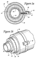
- Fig. 2b is a side view of the preferred embodiment of the present invention.
- the inner conduit 20 is shown disposed within several concentric, coaxial structures, including the first conductor 22, the heating element 24, the second conductor 26, and the sheath 28.
- AC main electrical power is used to operate the heating element.
- Any voltage generated by any power source as is expedient for the intended application may be provided, although an AC power source is provided in the preferred embodiment of the invention.
- the outside layers may be stripped from the ends of each conduit to expose the conductors.
- the conductors may also be terminated at the conduit source or destination Connections are made to the conductors as appropriate to supply electrical current to the heating element.
- jumpers or couplings may be provided to continue current flow to each section.
- a preferred embodiment of the present invention includes a power clamp 30 that is useful for coupling a power source to the first and second conductors and thus supply the beating element with power from a power source.
- the power clamp 30 includes a power terminal 32.
- Fig. 2a shows the power terminal 32 in cross section
- an insulator 34 includes a first terminal 36, for contacting the first or inner conductor 22, and a second terminal 38, for contacting the second or outer conductor 26. Actual contact between terminal 38 and conductor 26 is not shown in Figs. 2a and 2b.
- terminal 38 may contact outer conductor 26 in a manner similar to that shown for terminal 36 and inner conductor 22.
- power clamp 30 may itself comprise terminal 38. In such arrangement, power clamp 30 is provided in direct surrounding contact with outer conductor 26, and not surrounding sheath 28, as is shown in Figs. 2a and 2b.
- the power clamp may include any number of terminals as appropriate for the heating structure integrated into the conduit.
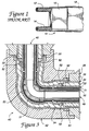
- Fig. 3 shows a cross sectional view of a corner coupling assembly 40 that may be used with the conduit of the present invention to couple sections of such conduit together at various angles, e.g. a 90° angle.
- the coupling assembly 40 includes a connector body 42, configured so as to surround the two sections of conduit 46, 48 that are to be coupled together.
- the connector body 42 is made of an electrically and thermally insulating material. As electrical insulators are often good thermal insulators, the selection of such material is a matter of choice.
- a thermally conductive electrically insulating layer 51 is provided between contact 52 and an inner fluid carrying conduit 53.
- the conduit 48 shown in Fig. 3 is of the same configuration as that shown in Figs. 2a and 2b. That is, the conduit 48 includes a fluid conduit 20 that is surrounded by a thermally conductive electrical insulator layer 31. The fluid conduit 20 is also surrounded by a heating element 24, which is provided between first and second electrical conductors 22, 26. The fluid conduit 20 is also surrounded by an outer thermal and electrical insulator layer 28.
- a polymer material 54 may also be provided within the coupling assembly to provide a connection between the heating elements within each of the conduits and to maintain even heating of the fluid contained within the inner conduit of such coupling.
- a coupling assembly for joining two lengths of conduit at a 90° angle is shown in Fig. 3, it is also possible to use such coupling arrangement to couple any number of lengths of conduit in any angle or angular arrangement, e.g. a T-coupling, X-coupling, gang-coupling, etc. may be provided as required by the use to which the conduit is put.
- the present invention is versatile and lends itself to many different application, including liquid and gas transport, and temperature maintenance and/or elevation.
- a round conduit is presented in the figures, the present invention could also be supplied in any number of configurations, including square, rectangular, oval, or other shapes.
- the present invention may also be provided with conduits having very complex shapes, such as coils, etc., which are extremely difficult to reliably heat with prior art heating techniques.
- the present invention may also be used in a heat reactor, such as is found in a semiconductor fabrication facility.
- a heat reactor such as is found in a semiconductor fabrication facility.
- Such reactor is a vessel which is in essence a large conduit that is sealed at each end.
- This embodiment of the invention replaces the expensive water/glycol system now used to regulate the reactor temperature.
- the present invention is provided in a double walled chamber having a heating element run between the two walls of the chamber, thereby providing a sandwich-like structure.
- an electrical current is applied to the two walls of the chamber, which then serve as electrical conductors, and the heating element disposed therebetween supplies the heat necessary for operation of the reactor.
Landscapes
- Engineering & Computer Science (AREA)
- General Engineering & Computer Science (AREA)
- Mechanical Engineering (AREA)
- Pipe Accessories (AREA)
- Resistance Heating (AREA)
Claims (13)
- Integrierte Rohrleitung, umfassend:eine innere Rohrleitung (20) zum Transportieren eines Fluids;einen ersten elektrischen Leiter (22);ein röhrenförmiges Heizelement (24); undeinen zweiten elektrischen Leiter (26), wobei das Heizelement (24) als Reaktion auf einen elektrischen Strom, der durch den ersten und den zweiten Leiter (22, 26) geliefert wird, Wärme erzeugt,
dadurch gekennzeichnet, daßder erste elektrische Leiter (22) konzentrisch zu und koaxial mit und über der inneren Rohrleitung (20) ausgebildet ist und sich um diese erstreckt;das röhrenförmige Heizelement (24) konzentrisch zu und koaxial mit dem ersten elektrischen Leiter (22) ausgebildet ist;der zweite elektrische Leiter (22) konzentrisch zu und koaxial mit und über dem Heizelement (24) ausgebildet ist und sich um dieses erstreckt; undder erste und der zweite elektrische Leiter (22, 26) auf entgegengesetzten Oberflächen des Heizelements (24) einander gegenüberliegen. - Rohrleitung nach Anspruch 1,
welche ferner umfaßt:einen thermisch leitenden elektrischen Isolator (31), der zwischen der inneren Rohrleitung (20) und dem ersten Leiter (22) angeordnet ist. - Rohrleitung nach Anspruch 1 oder 2,wobei das Heizelement (24) eine Heizvorrichtung aus mit leitendem Kohlenstoff gefülltem Polymer ist.
- Rohrleitung nach einem der Ansprüche 1 bis 3,wobei das Heizelement (24) selbstregelnd ist.
- Rohrleitung nach einem der Ansprüche 1 bis 4,
welche ferner umfaßt:eine thermisch und elektrisch isolierende Hülle (28), die konzentrisch zu und koaxial mit dem zweiten Leiter (26) ist. - Rohrleitung nach einem der Ansprüche 1 bis 5,wobei die innere Rohrleitung (20) aus einem Material ausgebildet ist, das aus der Gruppe ausgewählt ist, welche rostfreien Stahl, Stahl und Kupfer umfaßt.
- Rohrleitung nach einem der Ansprüche 1 bis 6,wobei das Heizelement (24) ein extrudiertes Material oder ein aufgebrachtes Material ist.
- Rohrleitung nach einem der Ansprüche 1 bis 7,wobei das Heizelement (24) in einem festgelegten Muster, vorzugsweise in einer linearen Struktur oder einer Spiralstruktur, ausgebildet ist.
- Rohrleitung nach einem der Ansprüche 1 bis 8, wobei die innere Rohrleitung (20) ein Gefäß definiert und wobei der erste und der zweite Leiter (22, 26) Gefäßwände sind.
- Rohrleitung nach einem der Ansprüche 1 bis 9,
welche ferner umfaßt:einen Leistungskoppler, einschließlich einer Klemme (30), die die Rohrleitung umgibt, einen Isolator (34) einteilig mit der Klemme (30), und mindestens zwei Anschlüsse (36, 38), wobei ein erster der Anschlüsse den ersten elektrischen Leiter (22) berührt und ein zweiter der Anschlüsse den zweiten elektrischen Leiter (26) berührt. - Rohrleitung nach einem der vorangehenden Ansprüche,
welche ferner umfaßt:einen Leistungskoppler (40) mit einem Körper (42) zum Aneinanderfügen von mindestens zwei Rohrleitungssegmenten, wobei der Leistungskoppler (40) mindestens zwei Kontakte (50, 52) aufweist, wobei die Kontakte (50, 52) dazu ausgelegt sind, elektrische Leiter (26, 22) in jedem Rohrleitungssegment mit elektrischen Leitern (26, 22) in jedem anderen Rohrleitungssegment zu koppeln. - Rohrleitung nach einem der vorangehenden Ansprüche,
welche ferner umfaßt:eine mehrlagige Struktur, einschließlich mindestens zwei Heizelementen. - Rohrleitung nach einem der vorangehenden Ansprüche, wobei der erste und der zweite Leiter (22, 26) aus einem geflochtenen Material oder einem umwickelten Material ausgebildet sind.
Applications Claiming Priority (2)
| Application Number | Priority Date | Filing Date | Title |
|---|---|---|---|
| US32072 | 1993-03-17 | ||
| US08/032,072 US5544275A (en) | 1993-03-17 | 1993-03-17 | Electrically heated fluid carrying conduit having integrated heating elements and electrical conductors |
Publications (2)
| Publication Number | Publication Date |
|---|---|
| EP0616166A1 EP0616166A1 (de) | 1994-09-21 |
| EP0616166B1 true EP0616166B1 (de) | 2000-02-09 |
Family
ID=21862942
Family Applications (1)
| Application Number | Title | Priority Date | Filing Date |
|---|---|---|---|
| EP94104186A Expired - Lifetime EP0616166B1 (de) | 1993-03-17 | 1994-03-17 | Heizbare Fluidleitung |
Country Status (3)
| Country | Link |
|---|---|
| US (1) | US5544275A (de) |
| EP (1) | EP0616166B1 (de) |
| JP (1) | JPH06323485A (de) |
Cited By (4)
| Publication number | Priority date | Publication date | Assignee | Title |
|---|---|---|---|---|
| CN101523976B (zh) * | 2006-09-29 | 2011-12-28 | 安东尼奥·波利 | 具有链节的柔性热盖 |
| US8550072B2 (en) | 2000-03-21 | 2013-10-08 | Fisher & Paykel Healthcare Limited | Apparatus for delivering humidified gases |
| EP2420715B1 (de) | 2010-08-20 | 2018-05-16 | Voss Automotive GmbH | Isolations- und/oder Schutzabdeckung für beheizbare Leitungsverbinder |
| US9989183B2 (en) | 2013-08-02 | 2018-06-05 | National Oilwell Varco Denmark I/S | Unbonded flexible pipe and an offshore system comprising an unbonded flexible pipe |
Families Citing this family (30)
| Publication number | Priority date | Publication date | Assignee | Title |
|---|---|---|---|---|
| ES2179218T3 (es) * | 1995-12-01 | 2003-01-16 | Suntory Ltd | Derivados de pirroloacepina. |
| JP2001518425A (ja) * | 1997-10-01 | 2001-10-16 | コンチネンタル・テベス・アーゲー・ウント・コンパニー・オーハーゲー | 自動車用液圧ブレーキシステム |
| US5933574A (en) * | 1998-02-09 | 1999-08-03 | Avansino; Gary L. | Heated fluid conduit |
| US6918389B2 (en) | 2000-03-21 | 2005-07-19 | Fisher & Paykel Healthcare Limited | Breathing assistance apparatus |
| US7588029B2 (en) | 2000-03-21 | 2009-09-15 | Fisher & Paykel Healthcare Limited | Humidified gases delivery apparatus |
| NZ523928A (en) * | 2000-07-28 | 2004-08-27 | Hydrogenics Corp | Method and apparatus for humidification and temperature control of incoming fuel cell process gas |
| US7051801B1 (en) * | 2000-07-28 | 2006-05-30 | Hydrogenics Corporation | Method and apparatus for humidification and temperature control of incoming fuel cell process gas |
| AU2002211121B2 (en) | 2000-10-16 | 2005-11-03 | Fisher & Paykel Healthcare Limited | Improvements to apparatus used for the humidification of gases in medical procedures |
| CA2408428C (en) * | 2001-10-17 | 2010-09-21 | Lorne R. Heise | Fluid conduit |
| US6792200B2 (en) | 2002-04-04 | 2004-09-14 | Arizona Public Service Company, Inc. | System and method for a pre-fabricated heat-traced header |
| ITBO20040518A1 (it) * | 2004-08-09 | 2004-11-09 | Eurosider S A S Di Milli Ottavio | Dispositivo e metodo per la produzione di azoto gassoso in pressione, in particolare destinato alla verniciatura |
| AU2005273119B2 (en) | 2004-08-20 | 2009-06-11 | Fisher & Paykel Healthcare Limited | Apparatus for measuring properties of gases supplied to a patient |
| DE102005050867A1 (de) † | 2005-10-24 | 2007-04-26 | Dbk David + Baader Gmbh | Beheizbarer Steckverbinder |
| US8526801B2 (en) | 2007-04-26 | 2013-09-03 | Voss Automotive Gmbh | Line connector for media lines |
| WO2009080501A1 (de) | 2007-12-21 | 2009-07-02 | Voss Automotive Gmbh | Leitungsverbinder für medienleitungen sowie konfektionierte medienleitung mit mindestens einem solchen leitungsverbinder |
| FR2967752B1 (fr) * | 2010-11-18 | 2013-07-05 | Itp Sa | Conduit isole et chauffe realise par des troncons double enveloppe et procede de pose du conduit |
| DE102011017811A1 (de) * | 2011-04-29 | 2012-10-31 | Evonik Degussa Gmbh | Temperierbare Rohrleitung für Offshoreanwendungen |
| GB2557116B (en) | 2011-06-03 | 2018-10-03 | Fisher & Paykel Healthcare Ltd | Medical tubes and methods of manufacture |
| AU2013264468B2 (en) | 2012-05-23 | 2018-08-09 | Fisher & Paykel Healthcare Limited | Flow path fault detection method for a respiratory assistance apparatus |
| US10589050B2 (en) | 2012-11-14 | 2020-03-17 | Fisher & Paykel Healthcare Limited | Zone heating for respiratory circuits |
| EP3708212B1 (de) | 2012-12-04 | 2024-05-22 | Fisher & Paykel Healthcare Limited | Beatmungsschlauch |
| WO2015060731A1 (en) | 2013-10-24 | 2015-04-30 | Fisher & Paykel Healthcare Limited | Delivery of respiratory gases |
| EP2876273B1 (de) * | 2013-11-22 | 2017-01-04 | TI Automotive (Heidelberg) GmbH | Verbindungsaggregat aus einer beheizbaren Kraftfahrzeugleitung und einem beheizbaren Verbinder |
| CN110947069A (zh) | 2013-12-20 | 2020-04-03 | 费雪派克医疗保健有限公司 | 加湿系统连接 |
| US10751498B2 (en) | 2014-03-17 | 2020-08-25 | Fisher & Paykel Healthcare Limited | Medical tubes for respiratory systems |
| WO2015171400A1 (en) * | 2014-05-04 | 2015-11-12 | Tolteq Group, LLC | Mating connector for downhole tool |
| SG10202002134QA (en) | 2015-09-09 | 2020-05-28 | Fisher & Paykel Healthcare Ltd | Zone heating for respiratory circuits |
| EP3544662B1 (de) | 2016-12-22 | 2024-11-27 | Fisher & Paykel Healthcare Limited | Medizinische schläuche und verfahren zur herstellung |
| US20190120183A1 (en) * | 2017-10-24 | 2019-04-25 | GM Global Technology Operations LLC | Heat source in cold vehicle conditions |
| CN113669541A (zh) * | 2021-08-23 | 2021-11-19 | 哈尔滨雪谷制冷设备有限公司 | 一种防冻管组件 |
Family Cites Families (18)
| Publication number | Priority date | Publication date | Assignee | Title |
|---|---|---|---|---|
| DE625773C (de) * | 1933-04-25 | 1936-02-14 | Continental Gummi Werke Ag | Elektrischer Heizkoerper fuer elektrische Widerstandsheizung |
| US2758150A (en) * | 1952-07-22 | 1956-08-07 | Gen Electric | Electrical connector for refrigerator defrosting means |
| AT191686B (de) * | 1953-05-05 | 1957-09-10 | Andrew George Ing Heron | Biegsamer Schlauch |
| US3019325A (en) * | 1958-12-15 | 1962-01-30 | Frank S Clouse | Fuel heating device |
| US3727029A (en) * | 1964-07-01 | 1973-04-10 | Moore & Co Samuel | Composite electrically heated tubing product |
| US3233202A (en) * | 1965-03-01 | 1966-02-01 | Physical Sciences Corp | Multiple contact connector |
| US3582968A (en) * | 1968-12-23 | 1971-06-01 | Texas Instruments Inc | Heaters and methods of making same |
| US3791415A (en) * | 1972-05-15 | 1974-02-12 | Hydraflow Supply Inc | Resilient flexible hose |
| US4429213A (en) * | 1978-10-20 | 1984-01-31 | Dayco Corporation | Electrically heated fluid conduit |
| DE2948591A1 (de) * | 1979-12-03 | 1981-06-11 | Fa. Fritz Eichenauer, 6744 Kandel | Durchlauferhitzer |
| JPS5685352A (en) * | 1979-12-13 | 1981-07-11 | Junkosha Co Ltd | Tubular heater |
| GB2084284B (en) * | 1980-09-22 | 1984-08-15 | Showa Denki Kogyo Co Ltd | Heated pipeline |
| US4532164A (en) * | 1983-09-15 | 1985-07-30 | Raychem Corporation | Heat-shrinkable article |
| DE3416105A1 (de) * | 1984-04-30 | 1985-11-07 | Meltex Verbindungstechnik GmbH, 2120 Lüneburg | Schmelzkleberschlauch |
| US4645906A (en) * | 1985-03-04 | 1987-02-24 | Thermon Manufacturing Company | Reduced resistance skin effect heat generating system |
| EP0312204A3 (de) * | 1987-10-09 | 1991-07-17 | Raychem Limited | Heizung eines Rohres mit leitfähigem Polymer |
| DE3900821C1 (en) * | 1989-01-13 | 1990-04-19 | Technoform Caprano + Brunnhofer Kg, 3501 Fuldabrueck, De | Fluid-carrying hose line for a motor vehicle |
| US4947012A (en) * | 1989-05-19 | 1990-08-07 | Minnesota Mining And Manufacturing Company | Electrofusion marker |
-
1993
- 1993-03-17 US US08/032,072 patent/US5544275A/en not_active Expired - Fee Related
-
1994
- 1994-03-17 JP JP6047128A patent/JPH06323485A/ja active Pending
- 1994-03-17 EP EP94104186A patent/EP0616166B1/de not_active Expired - Lifetime
Cited By (5)
| Publication number | Priority date | Publication date | Assignee | Title |
|---|---|---|---|---|
| US8550072B2 (en) | 2000-03-21 | 2013-10-08 | Fisher & Paykel Healthcare Limited | Apparatus for delivering humidified gases |
| CN101523976B (zh) * | 2006-09-29 | 2011-12-28 | 安东尼奥·波利 | 具有链节的柔性热盖 |
| EP2420715B1 (de) | 2010-08-20 | 2018-05-16 | Voss Automotive GmbH | Isolations- und/oder Schutzabdeckung für beheizbare Leitungsverbinder |
| EP2420715B2 (de) † | 2010-08-20 | 2023-07-19 | Voss Automotive GmbH | Isolations- und/oder Schutzabdeckung für beheizbare Leitungsverbinder |
| US9989183B2 (en) | 2013-08-02 | 2018-06-05 | National Oilwell Varco Denmark I/S | Unbonded flexible pipe and an offshore system comprising an unbonded flexible pipe |
Also Published As
| Publication number | Publication date |
|---|---|
| US5544275A (en) | 1996-08-06 |
| JPH06323485A (ja) | 1994-11-25 |
| EP0616166A1 (de) | 1994-09-21 |
Similar Documents
| Publication | Publication Date | Title |
|---|---|---|
| US5544275A (en) | Electrically heated fluid carrying conduit having integrated heating elements and electrical conductors | |
| US4532375A (en) | Heating device for utilizing the skin effect of alternating current | |
| US3617699A (en) | A system for electrically heating a fluid being transported in a pipe | |
| US3777117A (en) | Electric heat generating system | |
| US5390961A (en) | Dual wall thermally insulated conduit including skin effect heat tracing pipes | |
| SU1342433A3 (ru) | Изол ционна лента | |
| RU2034189C1 (ru) | Гибкий трубопровод для транспортировки веществ под давлением | |
| US4436565A (en) | Method of making a heating device for utilizing the skin effect of alternating current | |
| EP0206825A2 (de) | Doppelwandige Rohrleitung | |
| US7626146B2 (en) | Modular heater systems | |
| US4617449A (en) | Heating device for utilizing the skin effect of alternating current | |
| NL2007780C2 (en) | Thermally isolated heated pipeline made of double casing sections and laying process for such a pipeline. | |
| CN114641641A (zh) | 管道电加热系统 | |
| US3286078A (en) | Flexible internal heater | |
| US5775379A (en) | Insulation jacket for fluid carrying conduits | |
| US20190021138A1 (en) | Mineral insulated cable having reduced sheath temperature | |
| CN105191488A (zh) | 用于加热管线的设备 | |
| RU2449202C2 (ru) | Система электрического термостатирования трубопроводов или баков | |
| US3974398A (en) | Wire and steel tube as AC cable | |
| JPS6249520B2 (de) | ||
| US4661687A (en) | Method and apparatus for converting a fluid tracing system into an electrical tracing system | |
| KR102772645B1 (ko) | 라인히터 테스트장비 및 이를 이용한 테스트방법 | |
| KR20240066814A (ko) | 히트트레이싱시스템 및 이의 구축방법 | |
| RU2861625C1 (ru) | Система электрического обогрева трубопровода | |
| RU182642U1 (ru) | Устройство для обогрева промышленных объектов |
Legal Events
| Date | Code | Title | Description |
|---|---|---|---|
| PUAI | Public reference made under article 153(3) epc to a published international application that has entered the european phase |
Free format text: ORIGINAL CODE: 0009012 |
|
| AK | Designated contracting states |
Kind code of ref document: A1 Designated state(s): FR GB |
|
| 17P | Request for examination filed |
Effective date: 19950321 |
|
| 17Q | First examination report despatched |
Effective date: 19970226 |
|
| GRAG | Despatch of communication of intention to grant |
Free format text: ORIGINAL CODE: EPIDOS AGRA |
|
| GRAG | Despatch of communication of intention to grant |
Free format text: ORIGINAL CODE: EPIDOS AGRA |
|
| GRAG | Despatch of communication of intention to grant |
Free format text: ORIGINAL CODE: EPIDOS AGRA |
|
| GRAH | Despatch of communication of intention to grant a patent |
Free format text: ORIGINAL CODE: EPIDOS IGRA |
|
| GRAH | Despatch of communication of intention to grant a patent |
Free format text: ORIGINAL CODE: EPIDOS IGRA |
|
| GRAA | (expected) grant |
Free format text: ORIGINAL CODE: 0009210 |
|
| AK | Designated contracting states |
Kind code of ref document: B1 Designated state(s): FR GB |
|
| ET | Fr: translation filed | ||
| PLBE | No opposition filed within time limit |
Free format text: ORIGINAL CODE: 0009261 |
|
| STAA | Information on the status of an ep patent application or granted ep patent |
Free format text: STATUS: NO OPPOSITION FILED WITHIN TIME LIMIT |
|
| 26N | No opposition filed | ||
| PGFP | Annual fee paid to national office [announced via postgrant information from national office to epo] |
Ref country code: FR Payment date: 20010309 Year of fee payment: 8 |
|
| PGFP | Annual fee paid to national office [announced via postgrant information from national office to epo] |
Ref country code: GB Payment date: 20010316 Year of fee payment: 8 |
|
| REG | Reference to a national code |
Ref country code: GB Ref legal event code: IF02 |
|
| PG25 | Lapsed in a contracting state [announced via postgrant information from national office to epo] |
Ref country code: GB Free format text: LAPSE BECAUSE OF NON-PAYMENT OF DUE FEES Effective date: 20020317 |
|
| GBPC | Gb: european patent ceased through non-payment of renewal fee |
Effective date: 20020317 |
|
| PG25 | Lapsed in a contracting state [announced via postgrant information from national office to epo] |
Ref country code: FR Free format text: LAPSE BECAUSE OF NON-PAYMENT OF DUE FEES Effective date: 20021129 |
|
| REG | Reference to a national code |
Ref country code: FR Ref legal event code: ST |