EP0615216A2 - Coin packaging apparatus and system for managing the coin packaging apparatus - Google Patents
Coin packaging apparatus and system for managing the coin packaging apparatus Download PDFInfo
- Publication number
- EP0615216A2 EP0615216A2 EP94301635A EP94301635A EP0615216A2 EP 0615216 A2 EP0615216 A2 EP 0615216A2 EP 94301635 A EP94301635 A EP 94301635A EP 94301635 A EP94301635 A EP 94301635A EP 0615216 A2 EP0615216 A2 EP 0615216A2
- Authority
- EP
- European Patent Office
- Prior art keywords
- coin
- data
- passage
- coins
- unit
- Prior art date
- Legal status (The legal status is an assumption and is not a legal conclusion. Google has not performed a legal analysis and makes no representation as to the accuracy of the status listed.)
- Granted
Links
- 238000004806 packaging method and process Methods 0.000 title claims abstract description 116
- 238000000034 method Methods 0.000 claims description 16
- 230000008569 process Effects 0.000 claims description 13
- 238000013500 data storage Methods 0.000 description 21
- 230000007246 mechanism Effects 0.000 description 17
- 238000001514 detection method Methods 0.000 description 16
- 238000012545 processing Methods 0.000 description 15
- 230000001105 regulatory effect Effects 0.000 description 14
- 230000008859 change Effects 0.000 description 6
- 238000010276 construction Methods 0.000 description 6
- 238000010586 diagram Methods 0.000 description 6
- 230000002093 peripheral effect Effects 0.000 description 5
- 238000013461 design Methods 0.000 description 4
- 238000009825 accumulation Methods 0.000 description 3
- 230000006870 function Effects 0.000 description 3
- 230000002159 abnormal effect Effects 0.000 description 2
- 230000000903 blocking effect Effects 0.000 description 2
- 238000012858 packaging process Methods 0.000 description 2
- 230000005856 abnormality Effects 0.000 description 1
- 230000009471 action Effects 0.000 description 1
- 238000013459 approach Methods 0.000 description 1
- 230000008901 benefit Effects 0.000 description 1
- 238000004364 calculation method Methods 0.000 description 1
- 230000002950 deficient Effects 0.000 description 1
- 230000000994 depressogenic effect Effects 0.000 description 1
- 230000000694 effects Effects 0.000 description 1
- 230000008676 import Effects 0.000 description 1
- 230000006872 improvement Effects 0.000 description 1
- 238000012423 maintenance Methods 0.000 description 1
- 238000004519 manufacturing process Methods 0.000 description 1
- 230000004048 modification Effects 0.000 description 1
- 238000012986 modification Methods 0.000 description 1
- 238000012856 packing Methods 0.000 description 1
- 230000004044 response Effects 0.000 description 1
- 230000000630 rising effect Effects 0.000 description 1
Images


Classifications
-
- G—PHYSICS
- G07—CHECKING-DEVICES
- G07D—HANDLING OF COINS OR VALUABLE PAPERS, e.g. TESTING, SORTING BY DENOMINATIONS, COUNTING, DISPENSING, CHANGING OR DEPOSITING
- G07D9/00—Counting coins; Handling of coins not provided for in the other groups of this subclass
- G07D9/06—Devices for stacking or otherwise arranging coins on a support, e.g. apertured plate for use in counting coins
- G07D9/065—Devices for wrapping coins
Definitions
- the present invention relates generally to a coin packaging apparatus and, more particularly, to a coin packaging machine which automatically adjust width and height of a coin passage for processing such as selecting and counting coins and also inner diameter of a coin accumulating unit.
- the present invention further relates to a coin packaging apparatus managing system for totally storing and managing data relative to the processing by the coin packaging apparatus.
- Japanese Patent Laid-Open Publication No.59-121491(1984) discloses a known coin packaging machine for accumulating a predetermined number of coins and packaging the coins with a sheet of wrapping paper.
- the packaging machine disclosed in the same Patent Laid-Open Publication is constructed as follows.
- the coins are sent one by one out of a rotary disk and conveyed on a coin passage. Performed on this passage are processes such as selecting the coins having a small diameter, counting the coins to be packaged and stopping the operation.
- the coins are transferred into a coin accumulating unit provided at the terminal of the coin passage, wherein a predetermined number of coins are accumulated. After finishing the accumulation thereof, the accumulated coins are moved to a packaging unit and packaged with a sheet of wrapping paper.
- the width and height of the above coin passage and the inner diameter of the coin accumulating unit are adjustable corresponding to kinds of the coins for the purpose of processing the coins having different diameters and thicknesses.
- the adjustment of the coin passage width involves the following steps.
- a movable passage member movable in a crosswise direction of the coin passage among members constituting the coin passage is brought into contact with a polygonal cam.
- One of cam surfaces is selected by manually rotationally operating a kind-of-coin setting handle.
- the movable passage member is moved to a position corresponding to a diameter of the processed coin with the aid of this cam surface, thus adjusting the coin passage width.
- a thickness regulating member regulates the coins sent from the rotary disk in a one-layer state.
- Conveyor belts convey the coins while being press-fitted to the upper surface of the coin.
- the thickness regulating member and the conveyor belts are supported on a movable frame movable up and down.
- the thickness regulating member and the conveyor belts are moved up and down together with the movable frame by manually rotationally operating a height adjusting knob, thus adjusting the coin passage height.
- the coin accumulating unit is constructed such that support members for supporting peripheral lower surfaces of the coins are protruded from belt surfaces of a pair of belts disposed to set their traveling surfaces in a face-to-face relationship.
- the pair of belts are so supported as to be movable through parallel links, respectively.
- the parallel links are moved by one polygonal cam interlocking with the kind-of-coin setting handle. A surface-to-surface distance between the pair of belts is adjusted corresponding to the diameter of the processed coin as well as adjusting the inner diameter of the coin accumulating unit.
- a coin packaging unit three packaging rollers gradually approach each other while being rotated, whereby the accumulated coins are sandwiched therebetween.
- the wrapping paper is fed in between the rollers and the accumulated coins, thus packaging the accumulated coins with the wrapping paper.
- the upper and lower edges of the wrapping paper are swaged and tightly secured by swaging members.
- the coin packaging machine constructed in the manner described above typically incorporates a function to store items of data about a number of the coins counted and a number of the coins packaged (coin bar) throughout one day according to the kinds of coins and modes (a counting mode, a packaging mode, etc.). Further, the coin packaging machine also incorporates a function to store contents of abnormal states, if there are induced the abnormal states such as a jam of the coins on the coin passage, a defective-fed state and cut-off of the wrapping paper during the operation of the coin packaging machine (in the middle of counting and packaging processes). These items of operating data are printed out by a printer mounted in the coin packaging machine after an end of work in that day. The operating data printed out are manually input to a personal computer or the like and totally managed by the user.
- the conventional coin packaging machine presents a problems of being quite troublesome. That is, the kind-of-coin setting handle is manually rotationally operated corresponding to the kinds of the processed coins, thus adjusting the coin passage width and the inner diameter of the coin accumulating unit. On the other hand, it is required that the coin passage height be adjusted by manually rotationally operating the height adjusting knob. The operation is consequently diversified when changing the kind of the processed coin. Further, the cam for adjusting the coin passage width and the minor diameter of the coin accumulating unit is formed in the polygonal shape corresponding to several sorts of coins to be processed. Therefore, if, for instance, the coin packaging machines are exported to other countries, the cams adapted to coins circulated in the import countries have to be separately incorporated into the coin packaging machines. For this reason, it is impossible to effect a mass-production of the coin packaging machines and stock them.
- a coin packaging apparatus for conveying coins on a coin passage by sending out the coins one by one which have been supplied onto a rotary disk, performing necessary processes such as selecting and counting the coins on this passage, thereafter accumulating a predetermined number of coins in a coin accumulating unit and thus packaging the coins in a coin packaging unit after being accumulated
- said apparatus comprising: external storage medium driving means including a loading means for loading an external storage medium and a data writing means for writing, to said external storage medium loaded into said loading means, operating data containing at least one item of coin packaging number data, coin counting data and trouble occurring data; arithmetic means for calculating a passage width and a passage height of the coin passage and a inner diameter of said coin accumulating unit by use of the input coin data; kind-of-coin designating means for designating a kind of the coin to be processed; coin passage width adjusting means for adjusting the passage width of the coin passage in a non-stage manner; coin passage height adjusting means for adjusting a passage height
- a control unit operates a coin passage width adjusting unit, a coin passage height adjusting unit and a coin accumulating unit inner diameter adjusting unit. This is done based on a coin passage width, a coin passage height and an inner diameter of a coin accumulating unit that are calculated by an arithmetic unit by use of the coin data as well as on the kind of coin which is designated by a kind-of-coin setting unit. It is therefore possible to correspond to any kinds of coins.
- the operating data relative to an external storage medium are written by use of an external storage medium driving unit.
- the labor of operation of totally managing the operating data is thereby saved.
- the coin data are readily modified with a configuration wherein the coin data are read from and written to the external storage medium by employing the external storage medium driving unit. It is also possible to facilitate the operation of changing the kind of the processed coin.
- a coin packaging apparatus managing system for totally managing data about processes of a coin packaging machine for conveying coins on a coin passage by sending out the coins one by one which have been supplied onto a rotary disk, performing necessary processes such as selecting and counting the coins on this passage, thereafter accumulating a predetermined number of coins in a coin accumulating unit and thus packaging the coins in a coin packaging unit after being accumulated, said system comprising: coin packaging apparatus including:
- the operating data are written to the external storage medium by use of the external storage medium driving unit of the coin packaging machine.
- the operating data are read by employing the external storage medium driving unit of a data recording unit.
- the read data are managed by a control unit of this data recording unit, thereby eliminating necessity for manual inputting operation. The operation of totally managing the operating data is thus saved.
- the coin packaging apparatus relative to this system has the same construction with the first invention, and is therefore capable of corresponding to any kinds of coins.
- This coin packaging machine 1 is, as schematically illustrated in FIG. 1, in a coin throw-in hopper 3 which is opened in an upper portion of a machine body 2, there are provided a supply rotary disk 4 for receiving and supplying coins and a rotary disk 5 which receives the supply of the coins from the rotary disk 4.
- the rotary disks 4, 5 are respectively so provided as to be rotationally driven.
- a coin passage 6 for performing processes such as selecting and counting the coins extends in a direction substantially tangential to this rotary disk 5.
- a terminal of the coin passage 6 is provided with a coin accumulating unit 7 for accumulating a fixed number of coins.
- a lower part thereof is provided with a packaging unit 10, having three packaging rollers 9, 9, 9, for receiving and coins accumulated by the accumulating unit 7 and packaging the coins with a sheet of wrapping paper 8.
- the coins packaged (a bar of coins) therein are rejected from a throw-out port 11 formed downwardly of the machine body 2.
- reference numeral 12 designates a wrapping paper feed roller.
- a cutter 13 cuts the wrapping paper 8 to a necessary length.
- Packaging members 14, 14 swage (fold) and tightly secure upper and lower edges of the wrapping paper with which the accumulated coins are packaged.
- the wrapping paper feed roller 12, the cutter 13, the swaging members 14, 14 also function as a part of the packaging unit 10.
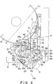
- the coin passage 6 includes, as illustrated in FIG. 2, a passage entrance bottom plate 15 located substantially flush with the disk 5.
- the coin passage 6 also includes fixed passage member 16 and movable passage members 17 provided posterior to this entrance bottom plate 15.
- the passage members 16, 17 cooperate to determine a selection groove width L (FIG. 1), corresponding to a coin diameter.
- the coin passage 6 further includes a passage exit bottom plate 18 located downstream of these passage members 16, 17.
- a small-diameter coin rejection hole 19 is formed between the entrance bottom plate 15 and the exit bottom plate 18.
- a loading mechanism 147 is provided in front of this coin packaging machine 1.
- the loading mechanism 147 loads a memory card into a coin data I/O unit (see FIG. 13) which will be stated later.
- the coin passage including a passage width adjusting unit 141 serving as a coin passage width adjusting section.
- FIG. 2 illustrates the coin passage in a maximum passage width state.
- FIG. 3 depicts the coin passage in a minimum passage width state.
- the above movable passage member 17 includes an extension portion 20 extending in a horizontal direction behind a rectilinear edge portion 17b having a stepped portion 17a for configuring the coin passage 6.
- This extension portion 20 is formed with slots 21, 21 bored in a direction orthogonal to the edge portion 17b.
- Guide rollers 22, 22 axially secured to the machine body 2 are fitted in the slots, 21, 21.
- the movable passage member 17 is thereby so supported as to be rectilinearly movable in such directions that the member 17 moves close to and away from the fixed passage member 16.
- a cam follower is pivotally attached to this extension portion 20.
- the cam follower 23 is biased by a spring 26 and is thereby always brought into contact with a peripheral surface of a non-stage cam 25 so fitted to the machine body 2 as to be movable about a shaft 24.
- This non-stage cam 25 assumes such a spiral shape that a radius gradually increases from its minimum radius portion 25a to a maximum radius portion 25b.
- This minimum radius portion 25a is formed with a recess 25c.
- the cam follower 23 is fitted in this recess 25c.
- the movable passage member 17 is located in a maximum opening position which is termed a fixed position.
- a fixed position detection sensor S1 detects the maximum opening position.
- the above non-stage cam 25 is rotated through a predetermined angle by means of a pulse motor M1.
- auxiliary passage member 27 assuming an L-shape as viewed in plane is connected via a pin 28 to a downstream end of the movable passage member 17.
- the other end of this auxiliary passage member 27 is biased by a spring 30 and is thereby come into contact with a fixed guide 29 toward the machine body 2.
- a position of a passage surface 27a of the auxiliary passage member 27 shifts.
- the passage surface 27a is located in such a position as to be slightly bent with respect to an edge portion 17b of the movable passage member 17.
- the passage surface 27a shifts in a rectilinear configuration with respect to the edge portion 17b of the movable passage member 17. Even when changing the passage width, the terminal of the coin passage 6 moves toward the center of the coin accumulating unit 7. At the same time, the arrangement is such that the terminal of the passage surface 27a of the auxiliary passage member 27 shifts closer to the coin accumulating unit 7 with a smaller diameter.
- An end portion, on the side of the movable passage member 17, of the above passage exit bottom plate 18 is rotatably supported on the machine body through a shaft 31.
- a pin 32 is protruded from a lower surface of this exit bottom plate 18.
- the pin 32 is fitted in a slot 34 of a portion, extending toward the coin passage 6, of the movable passage member 17. With a movement of the movable passage member 17 in such a direction as to narrow the passage width, the exit bottom plate 18 is gradually rotated clockwise in the FIG. 2 about the shaft 31 with the aid of the slot 34 and the pin 32 as well.
- auxiliary passage member 35 located on the line of extension of an edge portion 16b with a stepped portion 16a of the fixed passage member 16.
- a count sensor S2 for counting the number of coins for the passage
- a check sensor S3 for checking whether or not the coin has passed.
- a stopper 36 is so provided between these sensors S2, S3 as to freely advance on a passing trajectory of the coin. The stopper 36 actuated by an unillustrated solenoid stops, after a predetermined number of coins have passed, a coin subsequent thereto.
- a bottom plate support roller 38 is supported via an arm 37 at the free end of the exit bottom plate 18.
- This roller 38 is placed on a flat plate 39 on the side of the machine body 2 and supports the free end of the exit bottom plate 18. Further, rollers 40, 40, 40 for guiding the lower surface of the coin are axially provided at an exit end of the exit bottom plate 18.
- the auxiliary passage member 35 and the sensors S2, S3 are arranged so that an imaginary line connecting the member 35 to these sensors is always parallel to the passage surface 27a of the auxiliary passage member 27 on the side of the movable passage member 17 or in a state approximate thereto.
- a level sensor S4 detects a level of the coin existing on the rotary disk 5.
- a thickness regulating member 41 prevents an advancement of the coins superposed by twos into the coin passage 6.
- the thickness regulating member 41 faces at a spacing from an upper surface of the disk 5, wherein the spacing is larger than thickness of a single piece of in-process coin but smaller than thickness of two coins.
- a guide plate 42 is attached to the movable passage member 17 but placed on the rotary disk 5. The guide plate 42 guides the coins moving on the disk 5 toward a backward stream side in the rotating direction of the disk 5, thereby eliminating a jam of the coins.
- the symbol C represents the coin.
- a coin passage height adjusting unit 142 defined as a coin passage height adjusting section will be explained.
- This adjusting unit is actualized based on a height adjustment between the thickness regulating member 41 and a conveyor belt 43 for conveying the coin in the downstream direction while contacting the upper surface of the coin fed onto the coin passage 6.
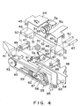
- FIG. 4 is a fragmentary perspective view illustrating a support mechanism of this conveyor belt 43.
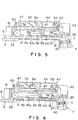
- FIG. 5 and 6 are sectional views showing cases where a height of the conveyor belt 43 is set in a highest position and a lowest position.
- a fixed plate 44 fixedly provided on the side of the machine body 2 has front and rear bearings 45, 45.
- One ends of two front and rear blocks 46, 46 are pivotally supported on the bearings 45, 45 via shafts 47, 47.
- Upper bearings 49, 49 of a movable frame 48 are pivotally supported on the opposite ends of those blocks 46, 46 through shafts 50, 50.
- bearings 51, 51 of the lower ends of the blocks 46, 46 are connected to each other through a link 52. These members constitute a parallel 4-node link mechanism.
- a pulley 53 on the entrance side of the conveyor belt 43 is attached via a shaft 54 to a side surface of this movable frame 48.
- downstream-side pulleys 55, 56 are axially fitted to an oscillating plate 57.
- a mid-part of this oscillating plate 57 is pivotally supported via a shaft 58 on the side surface of the movable frame 48. The other end thereof contacts a stopper 61 fitted to the movable frame 48, thus regulating descents of the pulleys 55, 56.
- a member 59 pivotally supported on the shaft 58 has a presser roller 43a at its top end.
- a tensile spring 60 is stretched between the member 59 and the oscillating plate 57.
- a proximal part of a detection plate 63 is pivotally supported via a shaft 64 on the downstream end of the movable frame 48.
- a contact member 65 is provided in the vicinity of the shaft 64.
- the contact member 65 faces to an upper portion of the coin accumulating unit 7 and detects an accumulation height of the coins.
- a detection member 64 provided at the top end thereof is related to a sensor (photo sensor) S5 provided on the movable frame 48. This detection member 64 detects, when actuating the sensor S5, that an upper space of the coin accumulating unit 7 is occupied.
- a motor (DC motor) M2 is attached to the lower surface of the fixed plate 44.
- a fixed position detection plate 66, a non-stage cam 67 and an angle-of-rotation detecting slit plate 68 are respectively fixedly fitted onto a shaft rotated by this motor M2.
- a fixed position detection sensor S6 is disposed on the periphery of this fixed position detection plate 66.
- an angle-of-rotation detection sensor S7 is disposed on the periphery of the slit plate 68.
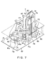
- pairs of pulleys 73, 74 and 75, 76 are axially fitted to upper and lower parts of right and left blocks 71, 72.
- Right and left belts 77, 78 are wound on the pulleys 73, 74 and 75, 76.
- the coins are stacked up between these belts 77, 78 in a face-to-face relationship.
- Protruded coin support members 79, 79, 80, 80 are provided on external surfaces of these belts 77, 78.
- the coin support members 79, 79, 80, 80 are provided in symmetric positions of the right and left belts 77, 78.
- the coin support members 79, 79, 80, 80 are provided by twos at equal intervals so that the coins are stacked twice with one revolutions of the belts 77, 78. Then, the right and left blocks 71, 72 are biased by a tensile spring 81 in such directions as to be pulled in each other.
- Positions of the blocks 71, 72 are adjusted in such directions as to move closer to and away from each other in a non-stage manner by means of a parallel link mechanism.
- This link mechanism is constructed of a first link 83, a second link 86, a third link 88, a fourth link 89 and a fifth link 90.
- the first link 83 has its mid-part rotatably supported through a shaft 83a on a base 82 within the horizontal plane.
- the block 71 on one side is connected via a shaft 71a to the top end of the first link 83.
- the second link 86 has its mid-part rotatably supported through a shaft 84 on the base 82.
- the block 72 on the other side is connected via a shaft 85 to one end of the second link 86.
- One end of the third link 88 is connected via the shaft 71a to the block 71, and the other end thereof is connected via a pin 87 to the second link 86.
- One ends of the fourth and fifth links 89, 90 are connected to the opposite sides of the blocks 71, 72, and the other ends thereof are pivotally supported on the base 82.
- a cam follower 91 is axially fitted to the other end of the first link 83 and contacts a peripheral surface of a non-stage cam 92 rotated by a pulse motor M3 installed on the base 82.
- a minimum interval position between the belts 77 and 78 i.e., a minimum radius position of the non-stage cam 92, is defined as a fixed position.
- a fixed position detection sensor S8 detects the fixed position.
- a blocking member 93 blocks an open face on the coin entering side between the belts 77, 78.
- a lever 94 has the blocking member 93 at its top end. A mid-part of the lever 94 is pivotally supported through the shaft 84 on the base 82.
- a link 95 is connected to the other end of the first link 83.
- a pin 97 provided at the other end of the lever 94 is fitted in a slot 96 formed in the other end portion of the link 95, thus providing a loose connection.
- This lever 94 is always biased by a tensile spring 98 in such a direction as to separate way from the coin accumulating unit 7.
- Guide members 99, 100 are fixedly fitted to the blocks 71, 72. The guide members 99, 100 prevent a deviation of the coin when accumulating the coins.
- a driving section of the belts 77, 78 of the coin accumulating unit 7 is, as in each of small- and large-diameter coin accumulating states shown in FIGURES 10 and 11, constructed of gears 103, 104, arms 105, 106, gears 107, 108 and a member 112.
- the gears 103, 104 are fixedly attached to shafts 101, 102 of the lower pulleys 74, 76 for the belts 77, 78.
- the arms 105, 106 are rotatably fitted to and supported on these shafts 101, 102.
- the gears 107, 108 are axially attached to the top ends of the arms 105, 106.
- the member 112 supporting shafts 109, 110 of these gears 107, 108 is capable of rising and lowering along a guide rod 111 extending in the vertical direction.
- a driving gear rotated by a pulse motor M4 meshes with the gear 103 disposed on the shaft of one pulley 74.
- the above gears 103, 107, 108, 104 are always set in an engaged state. Accordingly, even when a spacing between the belts 77 and 78 changes, rotations of the driving gear 113 are transferred to the right and left pulleys 74, 76 all the time.
- the coin packaging unit 10 is capable of processing any sorts of coins with a prior art construction and may therefore adopt the same construction as the conventional one, an explanation thereof will be omitted.
- a keyboard portion 115 is disposed to have ten keys arranged on one side thereof.
- the keyboard portion 115 includes a button 116 for designating a batch coin number in a count mode and a batch coin-bar number in a packaging mode.
- the keyboard portion 115 also includes a mode switching button 117 for wrapping and counting processes. Then, this keyboard portion 115 is operated, thereby making it possible to input the kinds of coins, diameters, thicknesses and packaging unit numbers of the coins to be processed. Further, a display portion 18 is formed on the other side of the panel unit 114.
- a position display segment 119 for displaying where a trouble happens a content display segment 120 for displaying a content of the trouble, a mode display segment 121 for displaying a count number and a batch, etc., a coin-bar/coin number display segment 122, a stored kind-of-coin display segment (entry type) 123 for recording that the coin data of the coins of specific kinds have been stored, a kind-of-coin display segment 124 for displaying a designated kind of the in-process coin and a packaging number display segment 125 for displaying a packaging unit number of the in-process coins.
- a coin-bar/coin number switching button 126 for designating a kind of the processed coin by sequentially displaying the display contents displayed on the kind-of-coin display segment 124 and the packaging number display segment 125 in a stored content sequence, i.e., in the order of items of the data recorded on the stored kind-of-coin display segment 123.
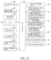
- FIG. 13 is a block diagram showing one example of a control system.
- a control unit 132 (which comprises an arithmetic means and a control means in the appended claims) controls the whole packaging machine. Signals are received by and transmitted to respective units which follow.
- An operation unit 133 comprises the start button 128, the stop button 129, the clear button 127, the coin-bar/coin number switching button 126, the mode switching button 117 and the designation button 116.
- a kind-of-coin designating unit 134 comprises the kind-of-coin display segment 124, the packaging number display segment 125, the down button 130 and the up button 131. The kind-of-coin designating unit 134 corresponds to the kind-of-coin designating means stated in the appended claims.
- a coin data I/O unit 135 is constructed of the keyboard portion 115 of the panel unit 114 and a memory card driver (corresponding to an "external storage medium driving means" in the appended claims) 146.
- This memory card driver 146 is employed for reading the coin data previously stored on a memory card (corresponding to an "external storage medium” in the claims) such as a ROM card, an IC card, etc..
- the memory card driver 146 is also used for writing pieces of operating data to the memory card. Note that the above-described coin data can be manually input by use of the keyboard portion 115. Further, the coin data read from the memory card can be also modified through the keyboard portion 115.
- the memory card driver 146 is employed for inputting or writing the modified coin data to the card through the keyboard portion 115.
- the display unit 136 comprises the position display segment 119, the content display segment 120, the mode display segment 121, the coin-bar/coin number display segment 122 and the stored kind-of-coin display segment 123.
- the storage unit 137 stores the coin data input by the coin data I/O unit 135, corresponding to the kinds of coins.
- the storage unit uses ,e.g., an EEPROM so that the contents of storage are not be erased even if the power is turned off.
- a coin counter unit 138 is constructed of the count sensor S2 and the check sensor S3.
- a coin stop unit 139 is composed of the stopper 36 and the unillustrated solenoid.
- a coin supply unit 140 is constructed of the rotary disks 4, 5 and the motors for driving these disks.
- a coin passage width adjusting unit 141 comprises a mechanism including the pulse motor M1, the fixed position detection sensor S1 and the non-stage cam 25.
- the coin passage height adjusting unit 142 is constructed of a mechanism including the DC motor M2, a rotating position detection sensor composed of the fixed position detection sensor S6 and the angle-of-ration detection sensor S7, and the non-stage cam 67.
- the accumulating unit minor-diameter adjusting unit 143 is constructed of a mechanism having the pulse motor M3, the fixed position detection sensor S8 and the non-stage cam 92.
- a coin accumulating unit 144 is composed of the pair of belts 77, 78 and the pulse motor M4 for revolving the belts.
- a coin packaging unit 145 is constructed of three pieces of packaging rollers 9, 9, 9 and an unillustrated motor for rotationally driving these rollers.
- FIG. 14 schematically illustrates an internal configuration of the memory card driver 146 incorporated into the above coin data I/O unit 135 (see FIG. 13).
- the memory card driver 146 comprises a loading mechanism 147 (corresponding to a "loading means” in the claims) for loading the memory card.
- the driver 146 also comprises a data reading/writing unit (corresponding to a "data writing means” in the claims) 148 for reading and writing the data from and to the memory card loaded into the loading mechanism 147.
- the driver 146 further includes a RAM (Random Access Memory) 150 for temporarily storing the data to be written to the memory card as well as the data read from the memory card.
- RAM Random Access Memory
- the RAM 150 includes a coin data storage area 150a, a coin counting data storage area 150b and a trouble occurring data storage area 150c.
- Stored in the coin data storage area 150a are, e.g., as items of coin data, a coin diameter D(1), a coin thickness T(1) and a packaging unit number M(1) according to the classified coins.
- the coin diameter D(1) and the coin thickness T(1) among those items of coin data are stored to two decimal places based on the millimeter unit. Note that these items may be stored on the units other than inches, etc., or alternatively the units may be selected.
- the coin data read from the memory card by the data reading/writing unit 148 can be stored in this coin data storage area 150a.
- the coin data manually input through the keyboard portion 115 of the panel unit 114 can be also stored in the storage area 150a.
- the coin data read from the memory card is manually input through the keyboard portion 115 and can be also modified.
- Results of the processes conducted throughout one day are stored in the coin counting data storage area 150b according to classifications in terms of the modes and kinds of the coins.
- the coin counting data according to the processing modes is itemized into a number of packaged coin bars (coin bar) which have undergone a packaging process in the packaging mode and a number of coins subjected to a counting process in the count mode. These items of data are written by the control unit 132.
- the control unit 132 writes contents and the time of troubles happened throughout one day to the trouble occurring data storage area 150c.
- the troubles imply, e.g., a jam of coins on the coin passage, ill-fed wrapping paper, a cut-out of the wrapping paper, etc..
- the contents of the coin data, the coin counting data and the trouble occurring data, which have been stored on the RAM 150 can be read by the data reading/writing unit 148 and written to the memory card. Further, the coin data stored on the memory card is also read and written to the RAM 150 by the data reading/writing unit 148.
- the storage contents of the respective storage areas 150a to 150c within the RAM 150 are stored on a single piece of memory card 151.
- the memory card 151 is also formed with a coin data storage area 151a, a coin counting data storage area 151b and a trouble occurring storage area 151c.
- the data may be read and written by the data reading/writing unit 148. With this processing, the respective items of data with respect to the single coin packaging machine can be stored on the single piece of memory card, and, therefore, a convenience in terms of usability can be given.
- the data relative to a plurality of coin packaging machines may be also stored in the single piece of memory card. More specifically, the storage area of the single memory card 152 is segmented into storage areas 152A, 152B, 152C, ... corresponding to the plurality of coin packaging machines. Furthermore, the storage area corresponding to each coin packaging machine is segmented into a coin data storage area 152a, a coin counting data storage area 152b and a trouble occurring data storage area 152c. When thus segmented, the single memory card can commonly applied to the plurality of coin packaging machines.
- items of data implying types A, B, C of the coin packaging machines are also stored in the respective storage areas 150a - 150c of coin packaging machines A, B, C.
- the data can be thereby received and transferred to the storage areas 152a - 152c, corresponding to the coin packaging machines A, B, C, of the memory card 152.
- the coin data storage area 152a is unified, and only the coin counting data storage area 152b and the trouble occurring data storage area 152c may be provided for every coin packaging machine.
- the number of the coin packaging machines to which the single memory card is capable of corresponding can be thereby increased by effectively making use of the storage areas of the memory card 152.
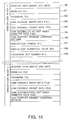
- FIG. 16 is a block diagram conceptually illustrating storage contents of the storage unit 137. An explanation will hereinafter be also given by exemplifying storage contents of a kind-of-coin block 1.
- An updated year, month and date of a relevant kind-of-coin block are stored in a first storage area 160.
- the updated year, month and date are given by a timer incorporated into the control unit 132.
- the updated year, month and date are automatically set for a change each time an inputting process in a normal input mode which will be mentioned alter is performed.
- the coin diameter D(1) is stored in a storage area 161, while the coin thickness T(1) is stored in a storage area 162.
- These items of data D(1), T(1) are input from the RAM 150 of the above memory driver 146 (see FIG. 4).
- An item of coin passage width data P1 is stored in a storage area 163.
- This data P1 indicates a number of input pulses to the pulse motor of the con passage width adjusting unit 141, the number of input pulses serving to set the selection groove width L (see FIG. 1) to a predetermine value by driving the movable passage member 17 (see FIG. 2).
- the data P1 is calculated by the control unit 132 in accordance with the coin diameter D(1) or directly input in a special input mode which will be stated later and then stored.
- P1 (C1 - D(1)) / C2 where values of C1, C2 are different depending on the design values of the movable passage member 17 and so on.
- Coin passage height data P2 is stored in a storage area 164.
- This data P2 indicates a number of output pulses to the angle-of-rotation detection sensor S7, wherein this number of output pulses serves to set the thickness regulating member 41 (see also FIG. 4) to a predetermined height by rotating the DC motor M2. That is, when the output pulse number of the angle-of-ration detection sensor S7 after starting the rotational drive of the DC motor M2 reaches P2, the DC motor M2 is stopped.
- the control unit 132 calculates P2 by use of the coin thickness T(1), or alternatively, P2 is directly input in the special input mode which will be stated later.
- C3, C4 take values which differ depending on a design value of the thickness regulating member 41.
- Coin accumulating unit inner diameter data P3 is stored in a storage area 165.
- This data P3 indicates a number of input pulses to the pulse motor of the accumulating unit inner diameter adjusting unit 143, wherein the input pulse number serves to set and change the spacing between the belts 77 and 78 in accordance with the coin diameter D(1).
- P3 is calculated by the control unit 132 or alternatively directly input and stored according to the special input mode which will be mentioned later.
- the arithmetic formula for use differs according to the coin diameter.
- a coin support unit lowering pattern is stored in a storage area 166.
- the coin support unit lower pattern is defined as data for determining lowering patterns of the coin support members 79, 80 provided on these belts 77, 78.
- the coin support members 79, 80 are lowered each time one coin is stacked.
- a descent quantity at this time is not always uniform but varies in accordance with a fixed pattern.
- the coin support unit lowering pattern is the data representing a variation pattern of the descent quantity at this moment.
- This lowering pattern is determined corresponding to the coin thickness T(1). Details thereof are to be the same as those disclosed in Japanese Patent Publication (Kokoku) No.3-17704.
- the storage unit 137 has the coin support unit lowering patterns predetermined corresponding to the coin thickness T(1) in the form of a table.
- the storage unit 137 reads a lowering pattern corresponding to an input coin thickness T(1) and stores a storage area with this pattern.
- a kind-of-coin symbol K(1) is stored in the storage area 167.
- a kind-of-coin numerical value H(1) is stored in a storage area 168.
- this kind-of-coin block 1 it is assumed, a block for storing the data about a one-dollar coin, a piece of control data for digitally displaying a dollar symbol on the display unit is stored in the form of the kind-of-coin symbol K(1), and [1.00] is stored as the kind-of-coin numerical value H(1).
- a packaging unit coin number M(1) is stored in a storage area 169. This value indicates a number of coins packaged as one length of coin bar.
- This data recorder may involve the use of, e.g., a personal computer, etc..
- a data recorder 170 comprises a memory card driver 171 and a control unit 172. Further, the memory card driver 171 includes a loading mechanism 173 for loading a memory card 151 and a data reading/writing unit 174 for reading and writing storage data on the memory card 151 loaded into this loading mechanism 173.
- the memory card 151 Loaded into the loading mechanism 173 is the memory card 151 to which the coin data I/O unit 135 (see FIG. 14) of the coin packaging machine 1 writes pieces of operating data (coin counting data and trouble occurring data). Then, the operating data are read from the loaded memory card 151. The read operating data are stored by the control unit 172. The operating data are employed for, e.g., managing the number of the packaged coin bars prepared throughout one day and the number of coins counted. In addition, the operating data may also be usable for a case of obtaining statistics about a trouble occurring situation.
- the coin data set by using the control unit 172 are written to the memory card 151 loaded into the loading mechanism 173.
- the coin data are also rad from the single memory card 151 and temporarily stored within the control unit 172.
- the coin data are subsequently written to another memory card 151, thus enabling the coin data to be copied.
- a memory card records coin data (kinds of coins, diameters, thicknesses and a rapping unit number) of circulation coins for a delivering destination (export destination).
- this memory card is set in the coin packaging machine through the coin data I/O unit 135.
- the coin data are input from this memory card to the RAM 150 (the coin data storage area 150a) of the coin data I/O unit 135.
- the coin data are transferred to and stored in the storage unit 137.
- a new memory card is prepared by the maker of the coin packaging machine, and the coin data for the coin packaging machine can be modified at the delivering destination.
- the coin data are to be partially modified or added with an item of coin data about the kind of the newly issued coin, an inputting process thereof can be performed by manipulating the keyboard portion 115. Further, when the coin data are thus modified, the coin data after being modified are rewritten to the memory card. The coin data after the modification may be input to another coin packing machine by use of this memory card. Note that all the coin data may be, as a matter of course, input by manipulating the keyboard portion 115.
- the up- and down-buttons 130, 131 conceived as the kind-of-coin designating unit 134 are manipulated.
- the kinds of coins, which have been stored in the storage unit 137, are thereby sequentially displayed on the kind-of-coin display segment 124.
- a kind of the processed coin is designated when stopped in such a state that a kind of the coin to be processed is displayed.
- the packaging unit number of the coins of that kind is also simultaneously displayed on the packaging number display segment 125.
- the control unit 132 Based on the designation of the kind of the coin, the control unit 132 reads the coin data of the coin of the designated kind from the storage unit 137. The control unit 132 gives a fixed position return command to each adjusting unit, whereby each adjusting unit is returned to its fixed position. Thereafter, the motor for each adjusting unit is rotated corresponding to a calculated pulse number and quantity of rotation, thereby automatically regulating each of the adjusting units.
- the non-stage cam 25 is rotated with the rotations of the pulse motor M1.
- the non-stage cam 25 is rotated clockwise through a predetermined angle from the fixed position shown in FIG. 2, thereby thrusting the cam follower 23.
- the movable passage member 17 consequently advances rightward in FIG. 2 by dint of guide actions of the guide rollers 22, 22 with the aid of the slots 21, 21.
- a spacing from the fixed passage member 16 is determined, and the movable passage member 17 stops. With this operation, the passage width is adjusted to a width corresponding to a diameter of the coin of the designated kind.
- the cam 25 has such a peripheral surface that the radius varies in the non-stage manner, and, therefore, the passage width can be adjusted, wherein an angle of rotation relative to one pulse of the pulse motor M1 is set as one pitch.
- the non-stage adjustment can be attained. It is possible to correspond to the coins having any magnitudes of major diameters on condition that these major diameters fall within a range defined by the maximum and minimum passage widths.
- the pin 28 serving as a fulcrum for the auxiliary passage member 27 also moves.
- the passage surface 27a gradually gets flush with the edge portion 17b of the movable passage member 17 as an angle to the edge portion 17b becomes smaller.
- the exit bottom plate 18 rotationally shifts clockwise about the shaft 31 trough the slot 34 with the aid of the slot 34 and the pin 32 as well.
- the auxiliary passage member 35 and the sensors S2, S3 come to positions parallel to the passage surface 27a of the auxiliary passage member 27.
- a non-stage cam 67 is rotated by a predetermined quantity with the rotations of the DC motor M2, with the result that a cam follower 69 is thrust down.
- the movable frame 48 is thereby lowered while resisting a biasing force of a spring 62.
- a height at which the lower surface of the conveyor belt 43 is positioned is, when press-fitted onto the upper surface of the coin of a designated kind, adjusted to such a position as to make the coin conveyable.
- the thickness regulating member 41 is also adjusted to such a position that only one coin is allowed to pass along the lower surface.
- the non-stage cam 92 is rotated clockwise through an angle corresponding to a pulse number from the position of FIG. 8. With this rotation, the cam follower 91 is thrust by the cam surface and gradually moves in such a direction as to get away from the center of the cam 92.
- the first link 83 is rotated clockwise about the shaft 82a, thereby moving the block 71 connected to one end thereof to the left hand in the FIG. 8. With this movement, the second link 86 is rotated counterclockwise about the shaft 84 through the third link 83, thereby rightward moving the block 72 on the other side.
- the spacing between the right and left belts 77, 78 located in the face-to-face relationship is thus expanded and set to a spacing adapted to the major diameter of the coin of the designated kind.
- the blocks 71, 72 make small movement downwardly in FIG. 8, i.e., in a direction away from the terminal of the coin passage 6.
- the blocks 71, 72 move farther away therefrom with a larger coin diameter and consequently take positions adapted to receive the coin.
- the lever 94 rotational shifts clockwise about the shaft 84 through the link 95.
- the block member 93 provided at its top end moves back and is located in a position adapted to increase the spacing between the belts 77 and 78.
- a inner diameter of a coin accumulating space shaped by the belts 77, 78, the block member 93, and the guides 99, 100 is thereby adjusted in the non-stage manner to a magnitude adapted to the major diameter of the coin of the designated kind.
- the arms 105, 106 are connected via the shafts 109, 110 to the member 112. Hence, the arms 105, 106 shift in such a direction as to assume a rectilinear configuration in combination with each other, thus following up an expansion of the spacing between the belts 77 and 78.
- the gears 107, 108 still keep the meshed state all the time.
- the driving force of the motor M4 is transferred via the gears 113, 103, 107, 108, 104 to the pulleys 74, 76 for the belts 77, 78 irrespective of the variations in the spacing between the right and left belts 77 and 78.
- all of the passage width and similarly the passage height of the coin passage 6 and the inner diameter of the coin accumulating unit 7 are set to values adapted to the coin diameter and thickness of the coin of the kind for processing.
- the rotary disk 4 When setting a kind of the coin and pushing the start button 128, the rotary disk 4 is driven, and the coins thrown in from the hopper 3 are supplied onto the rotary disk 5. At this time, the level sensor S4 monitors a state of existence of the coin on the rotary disk 5. A replenishing state is thus controlled.
- the coin on the rotary disk 5 comes under the lower surface of the coin thickness regulating member 41 from a peripheral portion thereof.
- the upper coin of the two-stacked coins is eliminated into a one-layer state.
- the coin is run into the coin passage 6 and depressed by the lower surface of the conveyor belt 43 on the entrance bottom plate 15.
- the coin With the revolution of the conveyor belt, the coin is conveyed astride the edge portions 16b, 17b of the fixed ad movable passage members 16, 17.
- the coin drops down from the rejection hole 19 between these edge portions.
- the coins reaching the terminal of the coin passage 6 are counted by the count sensor S2.
- the sensor S3 confirms their transits.
- the coins are guided by the rollers 40, 40... and enter the interior of the coin accumulating unit 7.
- the position display segment 119 (see FIG. 12) is operated to indicate a location where the trouble happens and the display segment 120 (see also FIG. 12) is operated to indicate content of the trouble.
- the content and occurring time of the trouble are written to the RAM 150 (the trouble occurring data storage area 150c) incorporated into the memory card driver 146 (see FIG. 14) provided in the coin data I/O unit 135.
- the support members 79, 80 of the right and left belts 77, 78 are located in the vicinity of the upper end. The coin sits astride these support members 79, 80. After the signal coin has sat thereon, the pulse motor M4 rotates by a predetermined quantity of pulses corresponding to the coin thickness on the basis of a signal from the sensor S3. The belts 77, 78 are thereby rotated, and the support members 79, 80 are lowered as described above.
- the operating solenoid of the stopper 36 is electrified in response to a signal thereof.
- the stopper 36 advances on the coin passage 6 and stops the coins subsequent thereto.
- a predetermined number of accumulated coins entering the coin accumulating unit 7 are, when the support members 79, 80 of the belts 77, 78 shift outward from the lower end, transferred to a support section (not shown).
- the coins are guided to the packaging unit 10 and packaged with the wrapping paper 8.
- the packaged coins are rejected from the throw-out port 11. Then, each time thus packaged coins are prepared once, the coin count data recorded on the RAM 150 (the coin count data storage area 150b) in the memory card driver 146 (see FIG. 14) provided in the coin data I/O unit 135 is rewritten.
- the wrapping paper 8 is defectively fed or cut off, there are operated the position display segment 119 (see FIG. 12) for indicating where the trouble happens and the content display segment 120 (see also FIG. 12) for indicating a content of the trouble.
- a content and an occurring time of the trouble are at the same time written to the RAM 150 (the trouble occurring data storage area 150c) incorporated into the memory card driver 146 (see FIG. 14) provided in the coin data I/O unit 135.
- the coin count data and the trouble occurring data stored on the RAM 150 are written to the trouble occurring data storage area 151c (see FIG. 15A) of the memory card loaded into the loading mechanism 147 by the memory card driver 146 at a stage of finishing the one-day operation of the coin packaging machine.
- the coin data and the operating data are written to the memory car in this way.
- the memory card is then employed for inputting the data to the data recorder 170 (see FIG. 17) described above.
- those items of data are not required to be manually input to the personal computer, etc.. It is therefore possible to reduce operating burdens such as saving and managing the data.
- the memory card to which those items of data are written is sent to the maker.
- the maker is therefore able to know a trouble occurring situation and an operating situation as well. This may serve as a reference to an improvement and a maintenance of the apparatus.
- the added or modified result is sent to the maker.
- the maker is accordingly capable of modifying the coin data for the coin packaging machine when delivered. This is effective especially in the coin packaging machines based on specifications for overseas.
- the operator arbitrarily selects the kind-of-coin block (see FIG. 15), and the coin data are stored in that block.
- An empty kind-of-coin block is, however, selected by the control unit 132, and the coin data may be stored in that block.
- data about a power supply frequency, etc. other than the above data may also be stored in the storage unit 137.
- the storage unit 137 may involve the use of a RAM having a battery backup in addition to the EEPROM.
- each item of data is not read from the EEPROM when adjusted, Instead, all the data are temporarily read from the EEPROM at the time of turning on the power supply and set-storing the data. All the data may be then stored in the RAM and read from this RAM when adjusted.
- the coin passage width data P1 the coin passage height data P2 and the coin accumulating unit inner diameter data P3 are immediately calculated.
- These items of data are stored in the storage unit 137.
- these items of data P1, P2, P3 may also be calculated when adjusted.
- the passage width and height of the coin passage for conveying the coins and the inner diameter of the accumulating unit are adjusted in the non-stage manner in accordance with the coin data of the coins to be processed. Besides, the passage width and height of the coin passage and the inner diameter of the coin accumulating unit are automatically adjusted based on the coin data of the coin data storage unit.
- the kind of the coin to be processed can be easily changed, and it is possible to correspond to the coins having any magnitudes of major diameters. It is also feasible to offer the overseas-oriented coins having extremely different diameters without changing the came each time.
- the coin packaging machine common to every country can be obtained.
- the construction is such that the coin data are read from the external storage medium by use of the external storage medium driving unit, and, therefore, the operation to change the kind of the processed coin can be facilitated.
- the operating data for the external storage medium are written by employing the external storage medium driving unit. It is therefore possible to save the labor of the operation for totally managing the operating data.
- the operating data are written to the external storage medium by use of the external storage medium driving unit of the coin packaging machine.
- the operating data are read by using the external storage medium of the data recorder.
- the read data are stored and managed by the control unit of this data recorder. A necessity for the manual inputting operation is therefore eliminated. It is possible to save the labor of the operation for totally managing the operating data.
Landscapes
- Physics & Mathematics (AREA)
- General Physics & Mathematics (AREA)
- Basic Packing Technique (AREA)
- Auxiliary Devices For And Details Of Packaging Control (AREA)
Abstract
Description
- The present invention relates generally to a coin packaging apparatus and, more particularly, to a coin packaging machine which automatically adjust width and height of a coin passage for processing such as selecting and counting coins and also inner diameter of a coin accumulating unit. The present invention further relates to a coin packaging apparatus managing system for totally storing and managing data relative to the processing by the coin packaging apparatus.
- For instance, Japanese Patent Laid-Open Publication (Kokai) No.59-121491(1984) discloses a known coin packaging machine for accumulating a predetermined number of coins and packaging the coins with a sheet of wrapping paper.
- The packaging machine disclosed in the same Patent Laid-Open Publication is constructed as follows. The coins are sent one by one out of a rotary disk and conveyed on a coin passage. Performed on this passage are processes such as selecting the coins having a small diameter, counting the coins to be packaged and stopping the operation. At the same time, the coins are transferred into a coin accumulating unit provided at the terminal of the coin passage, wherein a predetermined number of coins are accumulated. After finishing the accumulation thereof, the accumulated coins are moved to a packaging unit and packaged with a sheet of wrapping paper.
- The width and height of the above coin passage and the inner diameter of the coin accumulating unit are adjustable corresponding to kinds of the coins for the purpose of processing the coins having different diameters and thicknesses.
- More specifically, the adjustment of the coin passage width involves the following steps. A movable passage member movable in a crosswise direction of the coin passage among members constituting the coin passage is brought into contact with a polygonal cam. One of cam surfaces is selected by manually rotationally operating a kind-of-coin setting handle. The movable passage member is moved to a position corresponding to a diameter of the processed coin with the aid of this cam surface, thus adjusting the coin passage width.
- Further, the adjustment of the coin passage height is done as follows. A thickness regulating member regulates the coins sent from the rotary disk in a one-layer state. Conveyor belts convey the coins while being press-fitted to the upper surface of the coin. The thickness regulating member and the conveyor belts are supported on a movable frame movable up and down. The thickness regulating member and the conveyor belts are moved up and down together with the movable frame by manually rotationally operating a height adjusting knob, thus adjusting the coin passage height.
- Moreover, the coin accumulating unit is constructed such that support members for supporting peripheral lower surfaces of the coins are protruded from belt surfaces of a pair of belts disposed to set their traveling surfaces in a face-to-face relationship. The pair of belts are so supported as to be movable through parallel links, respectively. The parallel links are moved by one polygonal cam interlocking with the kind-of-coin setting handle. A surface-to-surface distance between the pair of belts is adjusted corresponding to the diameter of the processed coin as well as adjusting the inner diameter of the coin accumulating unit.
- Additionally, in a coin packaging unit, three packaging rollers gradually approach each other while being rotated, whereby the accumulated coins are sandwiched therebetween. The wrapping paper is fed in between the rollers and the accumulated coins, thus packaging the accumulated coins with the wrapping paper. The upper and lower edges of the wrapping paper are swaged and tightly secured by swaging members.
- The coin packaging machine constructed in the manner described above typically incorporates a function to store items of data about a number of the coins counted and a number of the coins packaged (coin bar) throughout one day according to the kinds of coins and modes (a counting mode, a packaging mode, etc.). Further, the coin packaging machine also incorporates a function to store contents of abnormal states, if there are induced the abnormal states such as a jam of the coins on the coin passage, a defective-fed state and cut-off of the wrapping paper during the operation of the coin packaging machine (in the middle of counting and packaging processes). These items of operating data are printed out by a printer mounted in the coin packaging machine after an end of work in that day. The operating data printed out are manually input to a personal computer or the like and totally managed by the user.
- The conventional coin packaging machine, however, presents a problems of being quite troublesome. That is, the kind-of-coin setting handle is manually rotationally operated corresponding to the kinds of the processed coins, thus adjusting the coin passage width and the inner diameter of the coin accumulating unit. On the other hand, it is required that the coin passage height be adjusted by manually rotationally operating the height adjusting knob. The operation is consequently diversified when changing the kind of the processed coin. Further, the cam for adjusting the coin passage width and the minor diameter of the coin accumulating unit is formed in the polygonal shape corresponding to several sorts of coins to be processed. Therefore, if, for instance, the coin packaging machines are exported to other countries, the cams adapted to coins circulated in the import countries have to be separately incorporated into the coin packaging machines. For this reason, it is impossible to effect a mass-production of the coin packaging machines and stock them.
- Moreover, if a redenomination of the currency is implemented, or if the number of kinds of the circulated coins increases, or if the diameters of the coins change, the cams in the coin packaging machines have to be replaced with new ones. This leads to a problem of requiring a tremendous amount of time and costs for the replacements thereof.
- In addition, when manually inputting, to the personal computer or the like, the operating data about the numbers of the coins processed in the manner described above and of the coin bars and also an abnormality occurring situation and totally managing the operating data, a problem arises, wherein the labor for the manual input augments with an increase in the number of the coin packaging machines for use.
- It is a primary object of the present invention to provide a coin packaging apparatus capable of easily changing kinds of coins to be processed, corresponding to any kinds of coins and saving the labor of operations of modifying items of coin data and totally managing items of operating data.
- It is a secondary object of the present invention to provide a coin packaging apparatus managing system for the coin packaging apparatus, which is capable of reducing the operation for totally managing the operating data.
- According to the first invention, there is provided a coin packaging apparatus for conveying coins on a coin passage by sending out the coins one by one which have been supplied onto a rotary disk, performing necessary processes such as selecting and counting the coins on this passage, thereafter accumulating a predetermined number of coins in a coin accumulating unit and thus packaging the coins in a coin packaging unit after being accumulated,
said apparatus comprising:
external storage medium driving means including a loading means for loading an external storage medium and a data writing means for writing, to said external storage medium loaded into said loading means, operating data containing at least one item of coin packaging number data, coin counting data and trouble occurring data;
arithmetic means for calculating a passage width and a passage height of the coin passage and a inner diameter of said coin accumulating unit by use of the input coin data;
kind-of-coin designating means for designating a kind of the coin to be processed;
coin passage width adjusting means for adjusting the passage width of the coin passage in a non-stage manner;
coin passage height adjusting means for adjusting a passage height of the coin passage in the non-stage manner;
coin accumulating unit inner diameter adjusting means for adjusting a inner diameter of said coin accumulating unit in the non-stage manner; and
control means for operating said coin passage width adjusting means, said coin passage height adjusting means and said coin accumulating unit inner diameter adjusting means on the basis of a calculated result of said arithmetic means with respect to the coins of the kind designated by said kind-of-coin designating means. - In the coin packaging apparatus according to the first invention, a control unit operates a coin passage width adjusting unit, a coin passage height adjusting unit and a coin accumulating unit inner diameter adjusting unit. This is done based on a coin passage width, a coin passage height and an inner diameter of a coin accumulating unit that are calculated by an arithmetic unit by use of the coin data as well as on the kind of coin which is designated by a kind-of-coin setting unit. It is therefore possible to correspond to any kinds of coins.
- Further, the operating data relative to an external storage medium are written by use of an external storage medium driving unit. The labor of operation of totally managing the operating data is thereby saved.
- Note that the coin data are readily modified with a configuration wherein the coin data are read from and written to the external storage medium by employing the external storage medium driving unit. It is also possible to facilitate the operation of changing the kind of the processed coin.
- According to the second invention, there is provided a coin packaging apparatus managing system for totally managing data about processes of a coin packaging machine for conveying coins on a coin passage by sending out the coins one by one which have been supplied onto a rotary disk, performing necessary processes such as selecting and counting the coins on this passage, thereafter accumulating a predetermined number of coins in a coin accumulating unit and thus packaging the coins in a coin packaging unit after being accumulated,
said system comprising:
coin packaging apparatus including: - (a) external storage medium driving means having a loading means for loading an external storage medium and a data writing means for writing, to said external storage medium loaded into said loading means, operating data containing at least one item of coin packaging number data, coin counting data and trouble occurring data;
- (b) arithmetic means for calculating a passage width and a passage height of the coin passage and a inner diameter of said coin accumulating unit by use of the input coin data;
- (c) kind-of-coin designating means for designating a kind of the coin to be processed;
- (d) coin passage width adjusting means for adjusting the passage width of the coin passage in a non-stage manner;
- (e) coin passage height adjusting means for adjusting a passage height of the coin passage in the non-stage manner;
- (f) coin accumulating unit inner diameter adjusting means for adjusting a inner diameter of said coin accumulating unit in the non-stage manner; and
- (g) control means for operating said coin passage width adjusting means, said coin passage height adjusting means and said coin accumulating unit inner diameter adjusting means on the basis of a calculated result of said arithmetic means with respect to the coins of the kind designated by said kind-of-coin designating means; and
- In the coin packaging apparatus managing system according to the second invention, the operating data are written to the external storage medium by use of the external storage medium driving unit of the coin packaging machine. At the same time, the operating data are read by employing the external storage medium driving unit of a data recording unit. The read data are managed by a control unit of this data recording unit, thereby eliminating necessity for manual inputting operation. The operation of totally managing the operating data is thus saved.
- Further, the coin packaging apparatus relative to this system has the same construction with the first invention, and is therefore capable of corresponding to any kinds of coins.
- Note that the following point is the same as the above-mentioned, wherein the coin data are read from or written to the external storage medium by use of the external storage medium driving unit of the coin packaging machine, and, with this construction, a change in the kind of coin to be processed is facilitated.
- Other objects and advantages of the present invention will become apparent during the following discussion in conjunction with the accompanying drawings, in which:
- FIG. 1 is a perspective view illustrating an outline of a coin packaging machine to which the present invention is applied;
- FIG. 2 is a plan view showing a coin passage when processing a coin having a large diameter;
- FIG. 3 is a plan view showing the coin passage when processing a coin having a small diameter;
- FIG. 4 is a fragmentary perspective view illustrating a passage height adjusting mechanism;
- FIG. 5 is a sectional view when processing a coin having a large thickness;
- FIG. 6 is a sectional view when processing a coin having a small thickness;
- FIG. 7 is a perspective view illustrating a coin accumulating unit;
- FIG. 8 is a plan view when processing the small-diameter coin;
- FIG. 9 is a plan view when processing the large-diameter coin;
- FIG. 10 is a front view showing a state of a driving system when processing the small-diameter coin;
- FIG. 11 is a front view showing a state of the driving system when processing the large-diameter coin;
- FIG. 12 is an explanatory view of an operation panel;
- FIG. 13 is a control block diagram;
- FIG. 14 is a block diagram schematically illustrating an internal configuration of a
memory card driver 146; - FIGS. 15A and 15B are conceptual views of assistance in explaining an example of recording data on a memory card;
- FIG. 16 is a block diagram conceptually showing a storage content of a storage unit; and
- FIG. 17 is a block diagram conceptually showing a configuration of a data recorder.
- The present invention will hereinafter be described by way of illustrative embodiments.
- First, a coin packaging machine in this embodiment will be explained.
- This
coin packaging machine 1 is, as schematically illustrated in FIG. 1, in a coin throw-inhopper 3 which is opened in an upper portion of amachine body 2, there are provided asupply rotary disk 4 for receiving and supplying coins and arotary disk 5 which receives the supply of the coins from therotary disk 4. Therotary disks coin passage 6 for performing processes such as selecting and counting the coins extends in a direction substantially tangential to thisrotary disk 5. A terminal of thecoin passage 6 is provided with acoin accumulating unit 7 for accumulating a fixed number of coins. A lower part thereof is provided with apackaging unit 10, having threepackaging rollers unit 7 and packaging the coins with a sheet of wrappingpaper 8. The coins packaged (a bar of coins) therein are rejected from a throw-out port 11 formed downwardly of themachine body 2. Referring to FIG. 1,reference numeral 12 designates a wrapping paper feed roller. Acutter 13 cuts thewrapping paper 8 to a necessary length.Packaging members paper feed roller 12, thecutter 13, theswaging members packaging unit 10. - The
coin passage 6 includes, as illustrated in FIG. 2, a passageentrance bottom plate 15 located substantially flush with thedisk 5. Thecoin passage 6 also includes fixedpassage member 16 andmovable passage members 17 provided posterior to thisentrance bottom plate 15. Thepassage members coin passage 6 further includes a passageexit bottom plate 18 located downstream of thesepassage members coin rejection hole 19 is formed between theentrance bottom plate 15 and theexit bottom plate 18. - Further, a
loading mechanism 147 is provided in front of thiscoin packaging machine 1. Theloading mechanism 147 loads a memory card into a coin data I/O unit (see FIG. 13) which will be stated later. - Given next is an explanation of the coin passage including a passage
width adjusting unit 141 serving as a coin passage width adjusting section. - FIG. 2 illustrates the coin passage in a maximum passage width state. FIG. 3 depicts the coin passage in a minimum passage width state.
- The above
movable passage member 17 includes anextension portion 20 extending in a horizontal direction behind arectilinear edge portion 17b having a steppedportion 17a for configuring thecoin passage 6. Thisextension portion 20 is formed withslots edge portion 17b.Guide rollers machine body 2 are fitted in the slots, 21, 21. Themovable passage member 17 is thereby so supported as to be rectilinearly movable in such directions that themember 17 moves close to and away from the fixedpassage member 16. A cam follower is pivotally attached to thisextension portion 20. Thecam follower 23 is biased by aspring 26 and is thereby always brought into contact with a peripheral surface of anon-stage cam 25 so fitted to themachine body 2 as to be movable about ashaft 24. - This
non-stage cam 25 assumes such a spiral shape that a radius gradually increases from itsminimum radius portion 25a to amaximum radius portion 25b. Thisminimum radius portion 25a is formed with arecess 25c. Thecam follower 23 is fitted in thisrecess 25c. In this state, themovable passage member 17 is located in a maximum opening position which is termed a fixed position. A fixed position detection sensor S1 detects the maximum opening position. The abovenon-stage cam 25 is rotated through a predetermined angle by means of a pulse motor M1. - One end of an
auxiliary passage member 27 assuming an L-shape as viewed in plane is connected via apin 28 to a downstream end of themovable passage member 17. The other end of thisauxiliary passage member 27 is biased by aspring 30 and is thereby come into contact with a fixedguide 29 toward themachine body 2. When themovable passage member 17 moves, a position of apassage surface 27a of theauxiliary passage member 27 shifts. When expanding a passage width, as illustrated in FIG. 2, thepassage surface 27a is located in such a position as to be slightly bent with respect to anedge portion 17b of themovable passage member 17. With a narrower width of the passage, thepassage surface 27a shifts in a rectilinear configuration with respect to theedge portion 17b of themovable passage member 17. Even when changing the passage width, the terminal of thecoin passage 6 moves toward the center of thecoin accumulating unit 7. At the same time, the arrangement is such that the terminal of thepassage surface 27a of theauxiliary passage member 27 shifts closer to thecoin accumulating unit 7 with a smaller diameter. - An end portion, on the side of the
movable passage member 17, of the above passageexit bottom plate 18 is rotatably supported on the machine body through ashaft 31. Apin 32 is protruded from a lower surface of thisexit bottom plate 18. Thepin 32 is fitted in aslot 34 of a portion, extending toward thecoin passage 6, of themovable passage member 17. With a movement of themovable passage member 17 in such a direction as to narrow the passage width, theexit bottom plate 18 is gradually rotated clockwise in the FIG. 2 about theshaft 31 with the aid of theslot 34 and thepin 32 as well. - Provided at a free end of the
exit bottom plate 18 is anauxiliary passage member 35 located on the line of extension of anedge portion 16b with a steppedportion 16a of the fixedpassage member 16. Provided downstream are a count sensor S2 for counting the number of coins for the passage and a check sensor S3 for checking whether or not the coin has passed. Astopper 36 is so provided between these sensors S2, S3 as to freely advance on a passing trajectory of the coin. Thestopper 36 actuated by an unillustrated solenoid stops, after a predetermined number of coins have passed, a coin subsequent thereto. A bottomplate support roller 38 is supported via anarm 37 at the free end of theexit bottom plate 18. Thisroller 38 is placed on aflat plate 39 on the side of themachine body 2 and supports the free end of theexit bottom plate 18. Further,rollers exit bottom plate 18. Theauxiliary passage member 35 and the sensors S2, S3 are arranged so that an imaginary line connecting themember 35 to these sensors is always parallel to thepassage surface 27a of theauxiliary passage member 27 on the side of themovable passage member 17 or in a state approximate thereto. Paying attention to FIG. 2, a level sensor S4 detects a level of the coin existing on therotary disk 5. Athickness regulating member 41 prevents an advancement of the coins superposed by twos into thecoin passage 6. For this purpose, thethickness regulating member 41 faces at a spacing from an upper surface of thedisk 5, wherein the spacing is larger than thickness of a single piece of in-process coin but smaller than thickness of two coins. Further, aguide plate 42 is attached to themovable passage member 17 but placed on therotary disk 5. Theguide plate 42 guides the coins moving on thedisk 5 toward a backward stream side in the rotating direction of thedisk 5, thereby eliminating a jam of the coins. The symbol C represents the coin. - Next, a coin passage
height adjusting unit 142 defined as a coin passage height adjusting section will be explained. This adjusting unit is actualized based on a height adjustment between thethickness regulating member 41 and aconveyor belt 43 for conveying the coin in the downstream direction while contacting the upper surface of the coin fed onto thecoin passage 6. - FIG. 4 is a fragmentary perspective view illustrating a support mechanism of this
conveyor belt 43. FIG. 5 and 6 are sectional views showing cases where a height of theconveyor belt 43 is set in a highest position and a lowest position. A fixedplate 44 fixedly provided on the side of themachine body 2 has front andrear bearings rear blocks bearings shafts Upper bearings movable frame 48 are pivotally supported on the opposite ends of thoseblocks shafts bearings blocks link 52. These members constitute a parallel 4-node link mechanism. - A
pulley 53 on the entrance side of theconveyor belt 43 is attached via ashaft 54 to a side surface of thismovable frame 48. Similarly, downstream-side pulleys 55, 56 are axially fitted to anoscillating plate 57. A mid-part of thisoscillating plate 57 is pivotally supported via ashaft 58 on the side surface of themovable frame 48. The other end thereof contacts astopper 61 fitted to themovable frame 48, thus regulating descents of thepulleys member 59 pivotally supported on theshaft 58 has apresser roller 43a at its top end. Atensile spring 60 is stretched between themember 59 and theoscillating plate 57. When a fixed or greater lifting force acts irrespective of a height position in which themovable frame 48 is located, i.e., when a thick coin enters, theoscillating plate 57 escapes upward. Atensile spring 62 is stretched between thismovable frame 48 and the fixedplate 44, thereby biasing themovable frame 48 upwards at all times. - A proximal part of a
detection plate 63 is pivotally supported via ashaft 64 on the downstream end of themovable frame 48. Acontact member 65 is provided in the vicinity of theshaft 64. Thecontact member 65 faces to an upper portion of thecoin accumulating unit 7 and detects an accumulation height of the coins. Adetection member 64 provided at the top end thereof is related to a sensor (photo sensor) S5 provided on themovable frame 48. Thisdetection member 64 detects, when actuating the sensor S5, that an upper space of thecoin accumulating unit 7 is occupied. - A motor (DC motor) M2 is attached to the lower surface of the fixed
plate 44. A fixedposition detection plate 66, anon-stage cam 67 and an angle-of-rotation detectingslit plate 68 are respectively fixedly fitted onto a shaft rotated by this motor M2. A fixed position detection sensor S6 is disposed on the periphery of this fixedposition detection plate 66. Besides, an angle-of-rotation detection sensor S7 is disposed on the periphery of theslit plate 68. - A
cam follower 69 axially provided in a central position of themovable frame 48 contacts the abovenon-stage cam 67. With rotations of thiscam 67, themovable frame 48 moves up and down through thecam follower 69. A position where thecam follower 69 contacts thecam 67 in the minimum radius position is defined as a fixed position. Further, the abovethickness regulating member 41 is fixedly attached to the entrance end of themovable frame 48. Thethickness regulating member 41 is also adjusted to a height adapted to a thickness of the coin to be treated, corresponding to an ascent and a descent of themovable frame 48. A pulley designated at 70 in the FIG. 4 receives a rotating force from a driving motor for theconveyor belt 43. - Given next is an explanation of a construction of the coin accumulating unit including an accumulating unit minor-
diameter adjusting unit 143 serving as a minor-diameter adjusting section. - As illustrated in a respective view of FIG. 7 and in plan views of FIGs. 8 and 9, pairs of
pulleys blocks belts pulleys belts coin support members belts coin support members belts coin support members belts blocks tensile spring 81 in such directions as to be pulled in each other. - Positions of the
blocks first link 83, asecond link 86, athird link 88, afourth link 89 and afifth link 90. Thefirst link 83 has its mid-part rotatably supported through ashaft 83a on abase 82 within the horizontal plane. Theblock 71 on one side is connected via ashaft 71a to the top end of thefirst link 83. Thesecond link 86 has its mid-part rotatably supported through ashaft 84 on thebase 82. Theblock 72 on the other side is connected via ashaft 85 to one end of thesecond link 86. One end of thethird link 88 is connected via theshaft 71a to theblock 71, and the other end thereof is connected via apin 87 to thesecond link 86. One ends of the fourth andfifth links blocks base 82. Acam follower 91 is axially fitted to the other end of thefirst link 83 and contacts a peripheral surface of anon-stage cam 92 rotated by a pulse motor M3 installed on thebase 82. A minimum interval position between thebelts non-stage cam 92, is defined as a fixed position. A fixed position detection sensor S8 detects the fixed position. - A blocking
member 93 blocks an open face on the coin entering side between thebelts lever 94 has the blockingmember 93 at its top end. A mid-part of thelever 94 is pivotally supported through theshaft 84 on thebase 82. Alink 95 is connected to the other end of thefirst link 83. Apin 97 provided at the other end of thelever 94 is fitted in aslot 96 formed in the other end portion of thelink 95, thus providing a loose connection. Thislever 94 is always biased by atensile spring 98 in such a direction as to separate way from thecoin accumulating unit 7.Guide members blocks guide members - A driving section of the
belts coin accumulating unit 7 is, as in each of small- and large-diameter coin accumulating states shown in FIGURES 10 and 11, constructed ofgears arms member 112. Thegears shafts 101, 102 of thelower pulleys belts arms shafts 101, 102. Thegears arms member 112 supportingshafts gears gear 103 disposed on the shaft of onepulley 74. The above gears 103, 107, 108, 104 are always set in an engaged state. Accordingly, even when a spacing between thebelts driving gear 113 are transferred to the right and leftpulleys - Since the
coin packaging unit 10 is capable of processing any sorts of coins with a prior art construction and may therefore adopt the same construction as the conventional one, an explanation thereof will be omitted. - The next explanation will deal with an operation/
display panel unit 114 provided on a front inclined portion of the upper surface of thecoin packaging machine 1. On thispanel unit 114, as shown in one example of a layout of FIG. 12, akeyboard portion 115 is disposed to have ten keys arranged on one side thereof. Thekeyboard portion 115 includes a button 116 for designating a batch coin number in a count mode and a batch coin-bar number in a packaging mode. Thekeyboard portion 115 also includes amode switching button 117 for wrapping and counting processes. Then, thiskeyboard portion 115 is operated, thereby making it possible to input the kinds of coins, diameters, thicknesses and packaging unit numbers of the coins to be processed. Further, adisplay portion 18 is formed on the other side of thepanel unit 114. Arranged in thisdisplay portion 118 are aposition display segment 119 for displaying where a trouble happens, acontent display segment 120 for displaying a content of the trouble, amode display segment 121 for displaying a count number and a batch, etc., a coin-bar/coinnumber display segment 122, a stored kind-of-coin display segment (entry type) 123 for recording that the coin data of the coins of specific kinds have been stored, a kind-of-coin display segment 124 for displaying a designated kind of the in-process coin and a packagingnumber display segment 125 for displaying a packaging unit number of the in-process coins. Further, separately from the above-mentioned, there are provided a coin-bar/coinnumber switching button 126, aclear button 127, astart button 128 and astop button 129. Provided moreover are up- and down-buttons 130, 131 for designating a kind of the processed coin by sequentially displaying the display contents displayed on the kind-of-coin display segment 124 and the packagingnumber display segment 125 in a stored content sequence, i.e., in the order of items of the data recorded on the stored kind-of-coin display segment 123. - FIG. 13 is a block diagram showing one example of a control system. A control unit 132 (which comprises an arithmetic means and a control means in the appended claims) controls the whole packaging machine. Signals are received by and transmitted to respective units which follow. An
operation unit 133 comprises thestart button 128, thestop button 129, theclear button 127, the coin-bar/coinnumber switching button 126, themode switching button 117 and the designation button 116. A kind-of-coin designating unit 134 comprises the kind-of-coin display segment 124, the packagingnumber display segment 125, the down button 130 and the up button 131. The kind-of-coin designating unit 134 corresponds to the kind-of-coin designating means stated in the appended claims. - A coin data I/
O unit 135 is constructed of thekeyboard portion 115 of thepanel unit 114 and a memory card driver (corresponding to an "external storage medium driving means" in the appended claims) 146. Thismemory card driver 146, as will be mentioned later (see FIG. 14), is employed for reading the coin data previously stored on a memory card (corresponding to an "external storage medium" in the claims) such as a ROM card, an IC card, etc.. Thememory card driver 146 is also used for writing pieces of operating data to the memory card. Note that the above-described coin data can be manually input by use of thekeyboard portion 115. Further, the coin data read from the memory card can be also modified through thekeyboard portion 115. Thememory card driver 146 is employed for inputting or writing the modified coin data to the card through thekeyboard portion 115. - The
display unit 136 comprises theposition display segment 119, thecontent display segment 120, themode display segment 121, the coin-bar/coinnumber display segment 122 and the stored kind-of-coin display segment 123. - The
storage unit 137 stores the coin data input by the coin data I/O unit 135, corresponding to the kinds of coins. The storage unit uses ,e.g., an EEPROM so that the contents of storage are not be erased even if the power is turned off. - Hereinafter, a
coin counter unit 138 is constructed of the count sensor S2 and the check sensor S3. Acoin stop unit 139 is composed of thestopper 36 and the unillustrated solenoid. Acoin supply unit 140 is constructed of therotary disks width adjusting unit 141 comprises a mechanism including the pulse motor M1, the fixed position detection sensor S1 and thenon-stage cam 25. Further, the coin passageheight adjusting unit 142 is constructed of a mechanism including the DC motor M2, a rotating position detection sensor composed of the fixed position detection sensor S6 and the angle-of-ration detection sensor S7, and thenon-stage cam 67. The accumulating unit minor-diameter adjusting unit 143 is constructed of a mechanism having the pulse motor M3, the fixed position detection sensor S8 and thenon-stage cam 92. - A
coin accumulating unit 144 is composed of the pair ofbelts coin packaging unit 145 is constructed of three pieces ofpackaging rollers - FIG. 14 schematically illustrates an internal configuration of the
memory card driver 146 incorporated into the above coin data I/O unit 135 (see FIG. 13). - As shown in FIG. 14, the
memory card driver 146 comprises a loading mechanism 147 (corresponding to a "loading means" in the claims) for loading the memory card. Thedriver 146 also comprises a data reading/writing unit (corresponding to a "data writing means" in the claims) 148 for reading and writing the data from and to the memory card loaded into theloading mechanism 147. Thedriver 146 further includes a RAM (Random Access Memory) 150 for temporarily storing the data to be written to the memory card as well as the data read from the memory card. - Further, the
RAM 150 includes a coindata storage area 150a, a coin countingdata storage area 150b and a trouble occurringdata storage area 150c. - Stored in the coin
data storage area 150a are, e.g., as items of coin data, a coin diameter D(1), a coin thickness T(1) and a packaging unit number M(1) according to the classified coins. The coin diameter D(1) and the coin thickness T(1) among those items of coin data are stored to two decimal places based on the millimeter unit. Note that these items may be stored on the units other than inches, etc., or alternatively the units may be selected. The coin data read from the memory card by the data reading/writing unit 148 can be stored in this coindata storage area 150a. At the same time, the coin data manually input through thekeyboard portion 115 of thepanel unit 114 can be also stored in thestorage area 150a. Moreover, the coin data read from the memory card is manually input through thekeyboard portion 115 and can be also modified. - Results of the processes conducted throughout one day are stored in the coin counting
data storage area 150b according to classifications in terms of the modes and kinds of the coins. For instance, the coin counting data according to the processing modes is itemized into a number of packaged coin bars (coin bar) which have undergone a packaging process in the packaging mode and a number of coins subjected to a counting process in the count mode. These items of data are written by thecontrol unit 132. - The
control unit 132 writes contents and the time of troubles happened throughout one day to the trouble occurringdata storage area 150c. The troubles imply, e.g., a jam of coins on the coin passage, ill-fed wrapping paper, a cut-out of the wrapping paper, etc.. - As stated above, the contents of the coin data, the coin counting data and the trouble occurring data, which have been stored on the
RAM 150, can be read by the data reading/writing unit 148 and written to the memory card. Further, the coin data stored on the memory card is also read and written to theRAM 150 by the data reading/writing unit 148. - Herein, the storage contents of the
respective storage areas 150a to 150c within theRAM 150 are stored on a single piece ofmemory card 151. In this case, as conceptually shown in FIG. 15A, thememory card 151 is also formed with a coindata storage area 151a, a coin counting data storage area 151b and a trouble occurringstorage area 151c. The data may be read and written by the data reading/writing unit 148. With this processing, the respective items of data with respect to the single coin packaging machine can be stored on the single piece of memory card, and, therefore, a convenience in terms of usability can be given. - Additionally, as illustrated in FIG. 15B, the data relative to a plurality of coin packaging machines may be also stored in the single piece of memory card. More specifically, the storage area of the
single memory card 152 is segmented intostorage areas data storage area 152b and a trouble occurringdata storage area 152c. When thus segmented, the single memory card can commonly applied to the plurality of coin packaging machines. In this case, items of data implying types A, B, C of the coin packaging machines are also stored in therespective storage areas 150a - 150c of coin packaging machines A, B, C. The data can be thereby received and transferred to the storage areas 152a - 152c, corresponding to the coin packaging machines A, B, C, of thememory card 152. Note that if the data contents of the coins treated by the coin packaging machines A, B, ... are identical with each other in this case, the coin data storage area 152a is unified, and only the coin countingdata storage area 152b and the trouble occurringdata storage area 152c may be provided for every coin packaging machine. The number of the coin packaging machines to which the single memory card is capable of corresponding can be thereby increased by effectively making use of the storage areas of thememory card 152. - Hereinafter, an explanation will be given by exemplifying a case where one memory card is employed for the single coin packaging machine as shown in FIG. 15A.
- FIG. 16 is a block diagram conceptually illustrating storage contents of the
storage unit 137. An explanation will hereinafter be also given by exemplifying storage contents of a kind-of-coin block 1. - An updated year, month and date of a relevant kind-of-coin block are stored in a
first storage area 160. The updated year, month and date are given by a timer incorporated into thecontrol unit 132. The updated year, month and date are automatically set for a change each time an inputting process in a normal input mode which will be mentioned alter is performed. - The coin diameter D(1) is stored in a
storage area 161, while the coin thickness T(1) is stored in astorage area 162. These items of data D(1), T(1) are input from theRAM 150 of the above memory driver 146 (see FIG. 4). - An item of coin passage width data P1 is stored in a
storage area 163. This data P1 indicates a number of input pulses to the pulse motor of the con passagewidth adjusting unit 141, the number of input pulses serving to set the selection groove width L (see FIG. 1) to a predetermine value by driving the movable passage member 17 (see FIG. 2). The data P1 is calculated by thecontrol unit 132 in accordance with the coin diameter D(1) or directly input in a special input mode which will be stated later and then stored. - Its calculation formula to be employed differs as follows. When the coin diameter is large, α1 ≧ D(1) > α2. When the coin diameter is intermediate, α2 ≧ D(1) > α3; and when small, α3 ≧ D(1). al through a3 take different values depending on deign values of the
movable passage member 17, etc.. - When α1 ≧ D(1) > α2, P1 is given by:

where values of C1, C2 are different depending on the design values of themovable passage member 17 and so on. - Similarly, when α2 ≧ D(1) > α3. P1 is given by:

- When α3 ≧ D(1), P1 is given such as:

- Coin passage height data P2 is stored in a
storage area 164. This data P2 indicates a number of output pulses to the angle-of-rotation detection sensor S7, wherein this number of output pulses serves to set the thickness regulating member 41 (see also FIG. 4) to a predetermined height by rotating the DC motor M2. That is, when the output pulse number of the angle-of-ration detection sensor S7 after starting the rotational drive of the DC motor M2 reaches P2, the DC motor M2 is stopped. - The
control unit 132 calculates P2 by use of the coin thickness T(1), or alternatively, P2 is directly input in the special input mode which will be stated later. P2 is given by the following arithmetic formula:
- Note that C3, C4 take values which differ depending on a design value of the
thickness regulating member 41. - Coin accumulating unit inner diameter data P3 is stored in a
storage area 165. This data P3 indicates a number of input pulses to the pulse motor of the accumulating unit innerdiameter adjusting unit 143, wherein the input pulse number serves to set and change the spacing between thebelts control unit 132 or alternatively directly input and stored according to the special input mode which will be mentioned later. - The arithmetic formula for use differs according to the coin diameter.

- Namely, a variety of integers are added to (C5 x D(1) - C6) in accordance with the diameter D(1), and a result thereof turns out P3. Note that C5, C6 and β1, β2, ... take values which differ depending on design values of the
belts - A coin support unit lowering pattern is stored in a
storage area 166. The coin support unit lower pattern is defined as data for determining lowering patterns of thecoin support members belts coin support members storage unit 137 has the coin support unit lowering patterns predetermined corresponding to the coin thickness T(1) in the form of a table. Thestorage unit 137 reads a lowering pattern corresponding to an input coin thickness T(1) and stores a storage area with this pattern. - A kind-of-coin symbol K(1) is stored in the
storage area 167. A kind-of-coin numerical value H(1) is stored in astorage area 168. For example, if this kind-of-coin block 1 is, it is assumed, a block for storing the data about a one-dollar coin, a piece of control data for digitally displaying a dollar symbol on the display unit is stored in the form of the kind-of-coin symbol K(1), and [1.00] is stored as the kind-of-coin numerical value H(1). - A packaging unit coin number M(1) is stored in a
storage area 169. This value indicates a number of coins packaged as one length of coin bar. - Note that the explanation has bee given herein by exemplifying the kind-of-
coin block 1, but the operation is absolutely the same with other kind-of-coin blocks - Subsequently, a data recorder relative to this embodiment will be explained. This data recorder may involve the use of, e.g., a personal computer, etc..
- As illustrated in FIG. 17, a
data recorder 170 comprises amemory card driver 171 and acontrol unit 172. Further, thememory card driver 171 includes aloading mechanism 173 for loading amemory card 151 and a data reading/writing unit 174 for reading and writing storage data on thememory card 151 loaded into thisloading mechanism 173. - Loaded into the
loading mechanism 173 is thememory card 151 to which the coin data I/O unit 135 (see FIG. 14) of thecoin packaging machine 1 writes pieces of operating data (coin counting data and trouble occurring data). Then, the operating data are read from the loadedmemory card 151. The read operating data are stored by thecontrol unit 172. The operating data are employed for, e.g., managing the number of the packaged coin bars prepared throughout one day and the number of coins counted. In addition, the operating data may also be usable for a case of obtaining statistics about a trouble occurring situation. - Further, according to the above-described
data recorder 170, the coin data set by using thecontrol unit 172 are written to thememory card 151 loaded into theloading mechanism 173. The coin data are also rad from thesingle memory card 151 and temporarily stored within thecontrol unit 172. The coin data are subsequently written to anothermemory card 151, thus enabling the coin data to be copied. - There will be next explained is an operation when actually using the above coin packaging machine.
- First, a memory card records coin data (kinds of coins, diameters, thicknesses and a rapping unit number) of circulation coins for a delivering destination (export destination). When delivering the coin packaging machine, this memory card is set in the coin packaging machine through the coin data I/
O unit 135. With this setting, as stated earlier, the coin data are input from this memory card to the RAM 150 (the coindata storage area 150a) of the coin data I/O unit 135. The coin data are transferred to and stored in thestorage unit 137. Besides, if the coin data are to be modified or have some addition as in the case of issuing new coins, a new memory card is prepared by the maker of the coin packaging machine, and the coin data for the coin packaging machine can be modified at the delivering destination. On the other hand, if the coin data are to be partially modified or added with an item of coin data about the kind of the newly issued coin, an inputting process thereof can be performed by manipulating thekeyboard portion 115. Further, when the coin data are thus modified, the coin data after being modified are rewritten to the memory card. The coin data after the modification may be input to another coin packing machine by use of this memory card. Note that all the coin data may be, as a matter of course, input by manipulating thekeyboard portion 115. - Moreover, when using the coin packaging machine, to start with, the up- and down-buttons 130, 131 conceived as the kind-of-
coin designating unit 134 are manipulated. The kinds of coins, which have been stored in thestorage unit 137, are thereby sequentially displayed on the kind-of-coin display segment 124. A kind of the processed coin is designated when stopped in such a state that a kind of the coin to be processed is displayed. Besides, at this time, the packaging unit number of the coins of that kind is also simultaneously displayed on the packagingnumber display segment 125. - Based on the designation of the kind of the coin, the
control unit 132 reads the coin data of the coin of the designated kind from thestorage unit 137. Thecontrol unit 132 gives a fixed position return command to each adjusting unit, whereby each adjusting unit is returned to its fixed position. Thereafter, the motor for each adjusting unit is rotated corresponding to a calculated pulse number and quantity of rotation, thereby automatically regulating each of the adjusting units. - In the coin passage
width adjusting unit 141, thenon-stage cam 25 is rotated with the rotations of the pulse motor M1. Thenon-stage cam 25 is rotated clockwise through a predetermined angle from the fixed position shown in FIG. 2, thereby thrusting thecam follower 23. Themovable passage member 17 consequently advances rightward in FIG. 2 by dint of guide actions of theguide rollers slots passage member 16 is determined, and themovable passage member 17 stops. With this operation, the passage width is adjusted to a width corresponding to a diameter of the coin of the designated kind. Accordingly, thecam 25 has such a peripheral surface that the radius varies in the non-stage manner, and, therefore, the passage width can be adjusted, wherein an angle of rotation relative to one pulse of the pulse motor M1 is set as one pitch. As a matter of fact, the non-stage adjustment can be attained. It is possible to correspond to the coins having any magnitudes of major diameters on condition that these major diameters fall within a range defined by the maximum and minimum passage widths. - With the rightward movement of the
movable passage member 17, thepin 28 serving as a fulcrum for theauxiliary passage member 27 also moves. Correspondingly, thepassage surface 27a gradually gets flush with theedge portion 17b of themovable passage member 17 as an angle to theedge portion 17b becomes smaller. Further, with the movement of themovable passage member 17, theexit bottom plate 18 rotationally shifts clockwise about theshaft 31 trough theslot 34 with the aid of theslot 34 and thepin 32 as well. Theauxiliary passage member 35 and the sensors S2, S3 come to positions parallel to thepassage surface 27a of theauxiliary passage member 27. Therefore, with a narrower coin passage width, a passage defined by theauxiliary passage members coin accumulating unit 7, with the result that an entering state into thecoin accumulating unit 7 does not change irrespective of the coin diameter. - On the other hand, in the coin passage
height adjusting unit 142, anon-stage cam 67 is rotated by a predetermined quantity with the rotations of the DC motor M2, with the result that acam follower 69 is thrust down. Themovable frame 48 is thereby lowered while resisting a biasing force of aspring 62. A height at which the lower surface of theconveyor belt 43 is positioned is, when press-fitted onto the upper surface of the coin of a designated kind, adjusted to such a position as to make the coin conveyable. Correspondingly, thethickness regulating member 41 is also adjusted to such a position that only one coin is allowed to pass along the lower surface. - In the accumulating unit inner
diameter adjusting unit 143, when the pulse motor M3 rotates, thenon-stage cam 92 is rotated clockwise through an angle corresponding to a pulse number from the position of FIG. 8. With this rotation, thecam follower 91 is thrust by the cam surface and gradually moves in such a direction as to get away from the center of thecam 92. Thefirst link 83 is rotated clockwise about theshaft 82a, thereby moving theblock 71 connected to one end thereof to the left hand in the FIG. 8. With this movement, thesecond link 86 is rotated counterclockwise about theshaft 84 through thethird link 83, thereby rightward moving theblock 72 on the other side. The spacing between the right and leftbelts links blocks coin passage 6. Theblocks first link 83, thelever 94 rotational shifts clockwise about theshaft 84 through thelink 95. Theblock member 93 provided at its top end moves back and is located in a position adapted to increase the spacing between thebelts belts block member 93, and theguides - In the driving system of the
coin accumulating unit 7, with the right and left movements of thebelts arms shafts member 112. Hence, thearms belts gears gears pulleys belts belts - Based on the operations described above, all of the passage width and similarly the passage height of the
coin passage 6 and the inner diameter of thecoin accumulating unit 7 are set to values adapted to the coin diameter and thickness of the coin of the kind for processing. - Next, the operations ranging from sending-off of the coins to the accumulation thereof will be explained.
- When setting a kind of the coin and pushing the
start button 128, therotary disk 4 is driven, and the coins thrown in from thehopper 3 are supplied onto therotary disk 5. At this time, the level sensor S4 monitors a state of existence of the coin on therotary disk 5. A replenishing state is thus controlled. - With the rotation of the
rotary disk 5, the coin on therotary disk 5 comes under the lower surface of the cointhickness regulating member 41 from a peripheral portion thereof. The upper coin of the two-stacked coins is eliminated into a one-layer state. The coin is run into thecoin passage 6 and depressed by the lower surface of theconveyor belt 43 on theentrance bottom plate 15. With the revolution of the conveyor belt, the coin is conveyed astride theedge portions movable passage members rejection hole 19 between these edge portions. - The coins reaching the terminal of the
coin passage 6 are counted by the count sensor S2. The sensor S3 confirms their transits. The coins are guided by therollers coin accumulating unit 7. - Herein, if the sensor S3 does not confirm the transmits thereof for a predetermined time, it is determined that the coins are jammed in the
coin passage 6. Then the position display segment 119 (see FIG. 12) is operated to indicate a location where the trouble happens and the display segment 120 (see also FIG. 12) is operated to indicate content of the trouble. At the same time, the content and occurring time of the trouble (trouble occurring data) are written to the RAM 150 (the trouble occurringdata storage area 150c) incorporated into the memory card driver 146 (see FIG. 14) provided in the coin data I/O unit 135. - In this
coin accumulating unit 7, thesupport members belts support members belts support members - When the coins of the packaging unit number are thus counted by the count sensor S2, the operating solenoid of the
stopper 36 is electrified in response to a signal thereof. Thestopper 36 advances on thecoin passage 6 and stops the coins subsequent thereto. - A predetermined number of accumulated coins entering the
coin accumulating unit 7 are, when thesupport members belts packaging unit 10 and packaged with thewrapping paper 8. The packaged coins are rejected from the throw-out port 11. Then, each time thus packaged coins are prepared once, the coin count data recorded on the RAM 150 (the coin countdata storage area 150b) in the memory card driver 146 (see FIG. 14) provided in the coin data I/O unit 135 is rewritten. - Herein, if the
wrapping paper 8 is defectively fed or cut off, there are operated the position display segment 119 (see FIG. 12) for indicating where the trouble happens and the content display segment 120 (see also FIG. 12) for indicating a content of the trouble. A content and an occurring time of the trouble (trouble occurring data) are at the same time written to the RAM 150 ( the trouble occurringdata storage area 150c) incorporated into the memory card driver 146 (see FIG. 14) provided in the coin data I/O unit 135. - Note that the coin count data and the trouble occurring data stored on the
RAM 150 are written to the trouble occurringdata storage area 151c (see FIG. 15A) of the memory card loaded into theloading mechanism 147 by thememory card driver 146 at a stage of finishing the one-day operation of the coin packaging machine. - The coin data and the operating data (the coin count data and the trouble occurring data) are written to the memory car in this way. The memory card is then employed for inputting the data to the data recorder 170 (see FIG. 17) described above. With this operation, in accordance with this embodiment, those items of data are not required to be manually input to the personal computer, etc.. It is therefore possible to reduce operating burdens such as saving and managing the data.
- Further, the memory card to which those items of data are written is sent to the maker. The maker is therefore able to know a trouble occurring situation and an operating situation as well. This may serve as a reference to an improvement and a maintenance of the apparatus.
- Moreover, when modifying the coin data or giving an addition thereto by manipulating the
keyboard portion 115 of thecoin packaging machine 1 for the reason of issuing the new money as explained earlier, the added or modified result is sent to the maker. In accordance with this, the maker is accordingly capable of modifying the coin data for the coin packaging machine when delivered. This is effective especially in the coin packaging machines based on specifications for overseas. - Note that the most preferred illustrative embodiment has been given with respect to the coin passage width adjusting unit, the passage height adjusting unit, the coin accumulating unit and the inner diameter adjusting unit. Specific configurations of the respective units can be arbitrarily changed in terms of their designs without departing from the scope and the technical concept of the present invention.
- For instance, when the coin data are stored in the
storage unit 137 in this embodiment, the operator arbitrarily selects the kind-of-coin block (see FIG. 15), and the coin data are stored in that block. An empty kind-of-coin block is, however, selected by thecontrol unit 132, and the coin data may be stored in that block. - Further, data about a power supply frequency, etc. other than the above data may also be stored in the
storage unit 137. - Moreover, the
storage unit 137 may involve the use of a RAM having a battery backup in addition to the EEPROM. - In combination therewith, each item of data is not read from the EEPROM when adjusted, Instead, all the data are temporarily read from the EEPROM at the time of turning on the power supply and set-storing the data. All the data may be then stored in the RAM and read from this RAM when adjusted.
- In addition, when inputting the coin data in this embodiment, the coin passage width data P1, the coin passage height data P2 and the coin accumulating unit inner diameter data P3 are immediately calculated. These items of data are stored in the
storage unit 137. However, these items of data P1, P2, P3 may also be calculated when adjusted. - As discussed above, according to the first invention, the passage width and height of the coin passage for conveying the coins and the inner diameter of the accumulating unit are adjusted in the non-stage manner in accordance with the coin data of the coins to be processed. Besides, the passage width and height of the coin passage and the inner diameter of the coin accumulating unit are automatically adjusted based on the coin data of the coin data storage unit. Hence, the kind of the coin to be processed can be easily changed, and it is possible to correspond to the coins having any magnitudes of major diameters. It is also feasible to offer the overseas-oriented coins having extremely different diameters without changing the came each time. The coin packaging machine common to every country can be obtained.
- Further, the construction is such that the coin data are read from the external storage medium by use of the external storage medium driving unit, and, therefore, the operation to change the kind of the processed coin can be facilitated. Moreover, the operating data for the external storage medium are written by employing the external storage medium driving unit. It is therefore possible to save the labor of the operation for totally managing the operating data.
- Additionally, according to the coin packaging machine managing system of the second invention, the operating data are written to the external storage medium by use of the external storage medium driving unit of the coin packaging machine. At the same time, the operating data are read by using the external storage medium of the data recorder. The read data are stored and managed by the control unit of this data recorder. A necessity for the manual inputting operation is therefore eliminated. It is possible to save the labor of the operation for totally managing the operating data.
data recording means having:
external data medium driving means having loading means for loading said external storage medium and data writing/reading means for reading the operating data from said external storage medium loaded into said loading means; and
control means for managing the operating data read by said external data medium driving means.
Claims (8)
- A coin packaging apparatus for conveying coins on a coin passage by sending out the coins one by one which have been supplied onto a rotary disk, performing necessary processes such as selecting and counting the coins on this passage, thereafter accumulating a predetermined number of coins in a coin accumulating unit and thus packaging the coins in a coin packaging unit after being accumulated,
said apparatus comprising:
external storage medium driving means (146) including a loading means (147) for loading an external storage medium and a data writing means (148) for writing, to said external storage medium loaded into said loading means, operating data containing at least one item of coin packaging number data, coin counting data and trouble occurring data;
arithmetic means (132) for calculating a passage width and a passage height of the coin passage and a inner diameter of said coin accumulating unit by use of the input coin data;
kind-of-coin designating means (134) for designating a kind of the coin to be processed;
coin passage width adjusting means (141) for adjusting the passage width of the coin passage in a non-stage manner;
coin passage height adjusting means (142) for adjusting a passage height of the coin passage in the non-stage manner;
coin accumulating unit inner diameter adjusting means (143) for adjusting a inner diameter of said coin accumulating unit in the non-stage manner; and
control means (132) for operating said coin passage width adjusting means, said coin passage height adjusting means and said coin accumulating unit inner diameter adjusting means on the basis of a calculated result of said arithmetic means with respect to the coins of the kind designated by said kind-of-coin designating means. - The coin packaging apparatus according to claim 1, wherein said external storage medium driving means further includes data reading/writing means (148) for reading or writing the coin data from or to said external storage medium.
- The coin packaging apparatus according to claim 1, wherein said external storage medium is a memory card (151, 152).
- The coin packaging apparatus according to claim 1, wherein each of said coin passage width adjusting means, said coin passage height adjusting means and said coin accumulating unit inner diameter adjusting means includes a cam (25, 67, 92) and a movable member to follow the cam, radius of the cam gradually increasing from the minimum radius to the maximum radius for continuously changing said coin passage width, said coin passage height and said coin accumulating unit height, respectively.
- A coin packaging apparatus managing system for totally managing data about processes of a coin packaging machine for conveying coins on a coin passage by sending out the coins one by one which have been supplied onto a rotary disk, performing necessary processes such as selecting and counting the coins on this passage, thereafter accumulating a predetermined number of coins in a coin accumulating unit and thus packaging the coins in a coin packaging unit after being accumulated,
said system comprising:
coin packaging apparatus including:(a) external storage medium driving means (146) having a loading means (147) for loading an external storage medium and a data writing means for writing, to said external storage medium loaded into said loading means, operating data containing at least one item of coin packaging number data, coin counting data and trouble occurring data;(b) arithmetic means (132) for calculating a passage width and a passage height of the coin passage and a inner diameter of said coin accumulating unit by use of the input coin data;(c) kind-of-coin designating means (132) for designating a kind of the coin to be processed;(d) coin passage width adjusting means (141) for adjusting the passage width of the coin passage in a non-stage manner;(e) coin passage height adjusting means (142) for adjusting a passage height of the coin passage in the non-stage manner;(f) coin accumulating unit inner diameter adjusting means (143) for adjusting a inner diameter of said coin accumulating unit in the non-stage manner; and(g) control means (132) for operating said coin passage width adjusting means, said coin passage height adjusting means and said coin accumulating unit inner diameter adjusting means on the basis of a calculated result of said arithmetic means with respect to the coins of the kind designated by said kind-of-coin designating means; anddata recording means (170) having:
external data medium driving means (171) having loading means (173) for loading said external storage medium and data writing/reading means (174) for reading the operating data from said external storage medium loaded into said loading means; and
control means (172) for managing the operating data read by said external data medium driving means. - The coin packaging apparatus managing system according to claim 5, wherein said external storage medium driving means further includes a data reading/writing means for reading or writing the coin data from or to said external storage medium.
- The coin packaging apparatus according to claim 5, wherein said external storage medium is a memory card (151, 152).
- The coin packaging apparatus according to claim 5, wherein each of said coin passage width adjusting means, said coin passage height adjusting means and said coin accumulating unit inner diameter adjusting means includes a cam (25, 67, 92) and a movable member to follow the cam, radius of the cam gradually increasing from the minimum radius to the maximum radius for continuously changing said coin passage width, said coin passage height and said coin accumulating unit height, respectively.
Applications Claiming Priority (2)
| Application Number | Priority Date | Filing Date | Title |
|---|---|---|---|
| JP46913/93 | 1993-03-08 | ||
| JP04691393A JP3542360B2 (en) | 1993-03-08 | 1993-03-08 | Coin wrapping machine and coin wrapping machine management system |
Publications (3)
| Publication Number | Publication Date |
|---|---|
| EP0615216A2 true EP0615216A2 (en) | 1994-09-14 |
| EP0615216A3 EP0615216A3 (en) | 1994-11-23 |
| EP0615216B1 EP0615216B1 (en) | 1998-11-11 |
Family
ID=12760589
Family Applications (1)
| Application Number | Title | Priority Date | Filing Date |
|---|---|---|---|
| EP19940301635 Expired - Lifetime EP0615216B1 (en) | 1993-03-08 | 1994-03-08 | Coin packaging apparatus and system for managing the coin packaging apparatus |
Country Status (6)
| Country | Link |
|---|---|
| EP (1) | EP0615216B1 (en) |
| JP (1) | JP3542360B2 (en) |
| KR (1) | KR0149736B1 (en) |
| CA (1) | CA2118551C (en) |
| DE (1) | DE69414439T2 (en) |
| ES (1) | ES2125403T3 (en) |
Cited By (2)
| Publication number | Priority date | Publication date | Assignee | Title |
|---|---|---|---|---|
| US9836909B2 (en) | 2016-04-06 | 2017-12-05 | Shuffle Master Gmbh & Co Kg | Chip sorting devices and related assemblies, components and methods |
| US10096192B1 (en) | 2017-08-30 | 2018-10-09 | Shuffle Master Gmbh & Co Kg | Chip sorting devices and related assemblies and methods |
Families Citing this family (5)
| Publication number | Priority date | Publication date | Assignee | Title |
|---|---|---|---|---|
| US6499277B1 (en) | 2000-02-22 | 2002-12-31 | Cummins-Allison Corp. | Coin wrapper |
| JP4623761B1 (en) * | 2010-07-08 | 2011-02-02 | ネット株式会社 | Medal selector and medal-type game machine using the medal selector |
| JP4836151B1 (en) * | 2010-11-09 | 2011-12-14 | ネット株式会社 | Medal selector and medal game machine |
| JP6619937B2 (en) * | 2015-02-10 | 2019-12-11 | グローリー株式会社 | Coin wrapping machine, coin wrapping system, and coin wrapping method |
| CN112810866A (en) * | 2020-12-30 | 2021-05-18 | 青岛日清食品机械有限公司 | Automatic currency distribution and packaging system for foreign currency |
Citations (3)
| Publication number | Priority date | Publication date | Assignee | Title |
|---|---|---|---|---|
| EP0432675A2 (en) * | 1989-12-15 | 1991-06-19 | Standardwerk Eugen Reis Gmbh | Apparatus for handling coins or similar disc-like objects |
| WO1991008952A1 (en) * | 1989-12-18 | 1991-06-27 | Cummins-Allison Corp. | Automatic adjustment device for a coin wrapping mechanism |
| EP0546772A1 (en) * | 1991-12-10 | 1993-06-16 | Glory Kogyo Kabushiki Kaisha | Coin packaging apparatus |
-
1993
- 1993-03-08 JP JP04691393A patent/JP3542360B2/en not_active Expired - Fee Related
-
1994
- 1994-03-08 ES ES94301635T patent/ES2125403T3/en not_active Expired - Lifetime
- 1994-03-08 CA CA 2118551 patent/CA2118551C/en not_active Expired - Fee Related
- 1994-03-08 DE DE1994614439 patent/DE69414439T2/en not_active Expired - Lifetime
- 1994-03-08 KR KR1019940004439A patent/KR0149736B1/en not_active IP Right Cessation
- 1994-03-08 EP EP19940301635 patent/EP0615216B1/en not_active Expired - Lifetime
Patent Citations (3)
| Publication number | Priority date | Publication date | Assignee | Title |
|---|---|---|---|---|
| EP0432675A2 (en) * | 1989-12-15 | 1991-06-19 | Standardwerk Eugen Reis Gmbh | Apparatus for handling coins or similar disc-like objects |
| WO1991008952A1 (en) * | 1989-12-18 | 1991-06-27 | Cummins-Allison Corp. | Automatic adjustment device for a coin wrapping mechanism |
| EP0546772A1 (en) * | 1991-12-10 | 1993-06-16 | Glory Kogyo Kabushiki Kaisha | Coin packaging apparatus |
Cited By (3)
| Publication number | Priority date | Publication date | Assignee | Title |
|---|---|---|---|---|
| US9836909B2 (en) | 2016-04-06 | 2017-12-05 | Shuffle Master Gmbh & Co Kg | Chip sorting devices and related assemblies, components and methods |
| US10255741B2 (en) | 2016-04-06 | 2019-04-09 | Shuffle Master Gmbh & Co Kg | Chip sorting devices and related assemblies, components and methods |
| US10096192B1 (en) | 2017-08-30 | 2018-10-09 | Shuffle Master Gmbh & Co Kg | Chip sorting devices and related assemblies and methods |
Also Published As
| Publication number | Publication date |
|---|---|
| EP0615216B1 (en) | 1998-11-11 |
| CA2118551A1 (en) | 1994-09-09 |
| EP0615216A3 (en) | 1994-11-23 |
| DE69414439D1 (en) | 1998-12-17 |
| CA2118551C (en) | 1998-06-23 |
| ES2125403T3 (en) | 1999-03-01 |
| JPH06263111A (en) | 1994-09-20 |
| KR0149736B1 (en) | 1998-10-15 |
| JP3542360B2 (en) | 2004-07-14 |
| DE69414439T2 (en) | 1999-04-22 |
Similar Documents
| Publication | Publication Date | Title |
|---|---|---|
| EP0546772B2 (en) | Coin packaging apparatus | |
| US4997406A (en) | Coin removing apparatus for coin handling machine | |
| US5000322A (en) | Bill receiving and dispensing machine | |
| US4365700A (en) | Money receiving and dispensing system | |
| US4618085A (en) | Sheet separating apparatus | |
| DE3928908A1 (en) | COIN WRAPPING MACHINE | |
| EP0615216B1 (en) | Coin packaging apparatus and system for managing the coin packaging apparatus | |
| CA2291329C (en) | Coin packaging apparatus | |
| US7073653B2 (en) | Coin handling machine | |
| AU635859B2 (en) | Cards processor | |
| EP0183234A2 (en) | Slip issuing apparatus | |
| US4993990A (en) | Unacceptable coin removing apparatus for coin handling machine | |
| US5557908A (en) | Coin processing machine | |
| JP3351858B2 (en) | Paper sheet counting device | |
| JP3414764B2 (en) | Coin wrapping machine | |
| JP3267697B2 (en) | Coin processing machine | |
| JP2004005746A (en) | Passage width regulator for coin handling apparatus | |
| JP3267696B2 (en) | Coin processing machine | |
| KR100341926B1 (en) | Method and device for managing giro paper for office automation instrument | |
| JP3018512B2 (en) | Coin depositing and dispensing machine | |
| KR950007844Y1 (en) | Recording paper keeping apparatus for cash dispenser | |
| JPS6245328Y2 (en) | ||
| JPH0241714Y2 (en) | ||
| JPH09270030A (en) | Automatic vending machine | |
| JPH05162727A (en) | Coin packaging machine |
Legal Events
| Date | Code | Title | Description |
|---|---|---|---|
| PUAI | Public reference made under article 153(3) epc to a published international application that has entered the european phase |
Free format text: ORIGINAL CODE: 0009012 |
|
| AK | Designated contracting states |
Kind code of ref document: A2 Designated state(s): DE ES FR GB IT SE |
|
| PUAL | Search report despatched |
Free format text: ORIGINAL CODE: 0009013 |
|
| AK | Designated contracting states |
Kind code of ref document: A3 Designated state(s): DE ES FR GB IT SE |
|
| 17P | Request for examination filed |
Effective date: 19950503 |
|
| 17Q | First examination report despatched |
Effective date: 19961030 |
|
| GRAG | Despatch of communication of intention to grant |
Free format text: ORIGINAL CODE: EPIDOS AGRA |
|
| GRAG | Despatch of communication of intention to grant |
Free format text: ORIGINAL CODE: EPIDOS AGRA |
|
| GRAH | Despatch of communication of intention to grant a patent |
Free format text: ORIGINAL CODE: EPIDOS IGRA |
|
| GRAH | Despatch of communication of intention to grant a patent |
Free format text: ORIGINAL CODE: EPIDOS IGRA |
|
| GRAA | (expected) grant |
Free format text: ORIGINAL CODE: 0009210 |
|
| AK | Designated contracting states |
Kind code of ref document: B1 Designated state(s): DE ES FR GB IT SE |
|
| REF | Corresponds to: |
Ref document number: 69414439 Country of ref document: DE Date of ref document: 19981217 |
|
| ET | Fr: translation filed | ||
| ITF | It: translation for a ep patent filed | ||
| REG | Reference to a national code |
Ref country code: ES Ref legal event code: FG2A Ref document number: 2125403 Country of ref document: ES Kind code of ref document: T3 |
|
| PLBE | No opposition filed within time limit |
Free format text: ORIGINAL CODE: 0009261 |
|
| STAA | Information on the status of an ep patent application or granted ep patent |
Free format text: STATUS: NO OPPOSITION FILED WITHIN TIME LIMIT |
|
| 26N | No opposition filed | ||
| REG | Reference to a national code |
Ref country code: GB Ref legal event code: IF02 |
|
| PGFP | Annual fee paid to national office [announced via postgrant information from national office to epo] |
Ref country code: ES Payment date: 20100319 Year of fee payment: 17 |
|
| PGFP | Annual fee paid to national office [announced via postgrant information from national office to epo] |
Ref country code: GB Payment date: 20100325 Year of fee payment: 17 |
|
| GBPC | Gb: european patent ceased through non-payment of renewal fee |
Effective date: 20110308 |
|
| PG25 | Lapsed in a contracting state [announced via postgrant information from national office to epo] |
Ref country code: GB Free format text: LAPSE BECAUSE OF NON-PAYMENT OF DUE FEES Effective date: 20110308 |
|
| REG | Reference to a national code |
Ref country code: ES Ref legal event code: FD2A Effective date: 20120424 |
|
| PGFP | Annual fee paid to national office [announced via postgrant information from national office to epo] |
Ref country code: FR Payment date: 20120319 Year of fee payment: 19 |
|
| PGFP | Annual fee paid to national office [announced via postgrant information from national office to epo] |
Ref country code: SE Payment date: 20120313 Year of fee payment: 19 Ref country code: IT Payment date: 20120323 Year of fee payment: 19 |
|
| PG25 | Lapsed in a contracting state [announced via postgrant information from national office to epo] |
Ref country code: ES Free format text: LAPSE BECAUSE OF NON-PAYMENT OF DUE FEES Effective date: 20110309 |
|
| PGFP | Annual fee paid to national office [announced via postgrant information from national office to epo] |
Ref country code: DE Payment date: 20120404 Year of fee payment: 19 |
|
| REG | Reference to a national code |
Ref country code: SE Ref legal event code: EUG |
|
| PG25 | Lapsed in a contracting state [announced via postgrant information from national office to epo] |
Ref country code: SE Free format text: LAPSE BECAUSE OF NON-PAYMENT OF DUE FEES Effective date: 20130309 |
|
| REG | Reference to a national code |
Ref country code: FR Ref legal event code: ST Effective date: 20131129 |
|
| REG | Reference to a national code |
Ref country code: DE Ref legal event code: R119 Ref document number: 69414439 Country of ref document: DE Effective date: 20131001 |
|
| PG25 | Lapsed in a contracting state [announced via postgrant information from national office to epo] |
Ref country code: FR Free format text: LAPSE BECAUSE OF NON-PAYMENT OF DUE FEES Effective date: 20130402 Ref country code: DE Free format text: LAPSE BECAUSE OF NON-PAYMENT OF DUE FEES Effective date: 20131001 |
|
| PG25 | Lapsed in a contracting state [announced via postgrant information from national office to epo] |
Ref country code: IT Free format text: LAPSE BECAUSE OF NON-PAYMENT OF DUE FEES Effective date: 20130308 |