EP0615134B1 - Verbesserte NMR-Sonde mit B1-Gradientenspulen - Google Patents
Verbesserte NMR-Sonde mit B1-Gradientenspulen Download PDFInfo
- Publication number
- EP0615134B1 EP0615134B1 EP94103458A EP94103458A EP0615134B1 EP 0615134 B1 EP0615134 B1 EP 0615134B1 EP 94103458 A EP94103458 A EP 94103458A EP 94103458 A EP94103458 A EP 94103458A EP 0615134 B1 EP0615134 B1 EP 0615134B1
- Authority
- EP
- European Patent Office
- Prior art keywords
- coil
- field
- gradient
- magnetic field
- coils
- Prior art date
- Legal status (The legal status is an assumption and is not a legal conclusion. Google has not performed a legal analysis and makes no representation as to the accuracy of the status listed.)
- Expired - Lifetime
Links
- 239000000523 sample Substances 0.000 title claims description 60
- 238000005481 NMR spectroscopy Methods 0.000 claims description 28
- 238000004804 winding Methods 0.000 claims description 11
- 238000012565 NMR experiment Methods 0.000 claims 1
- 230000005415 magnetization Effects 0.000 description 16
- 238000010586 diagram Methods 0.000 description 13
- 238000013461 design Methods 0.000 description 12
- 238000013459 approach Methods 0.000 description 8
- 230000003068 static effect Effects 0.000 description 8
- 238000010276 construction Methods 0.000 description 6
- 230000007246 mechanism Effects 0.000 description 6
- 238000000034 method Methods 0.000 description 5
- 230000001427 coherent effect Effects 0.000 description 2
- 239000004020 conductor Substances 0.000 description 2
- 230000001419 dependent effect Effects 0.000 description 2
- 238000009792 diffusion process Methods 0.000 description 2
- 230000009977 dual effect Effects 0.000 description 2
- 238000003384 imaging method Methods 0.000 description 2
- 230000003993 interaction Effects 0.000 description 2
- 238000005259 measurement Methods 0.000 description 2
- 238000012986 modification Methods 0.000 description 2
- 230000004048 modification Effects 0.000 description 2
- 230000037361 pathway Effects 0.000 description 2
- 238000012216 screening Methods 0.000 description 2
- 239000000126 substance Substances 0.000 description 2
- 239000003990 capacitor Substances 0.000 description 1
- 238000007796 conventional method Methods 0.000 description 1
- 230000000694 effects Effects 0.000 description 1
- 230000004807 localization Effects 0.000 description 1
- 238000000140 multiple quantum filter Methods 0.000 description 1
- 238000000655 nuclear magnetic resonance spectrum Methods 0.000 description 1
- 230000008569 process Effects 0.000 description 1
- 239000002904 solvent Substances 0.000 description 1
- 238000004611 spectroscopical analysis Methods 0.000 description 1
- 230000001629 suppression Effects 0.000 description 1
- 238000012546 transfer Methods 0.000 description 1
Images


Classifications
-
- G—PHYSICS
- G01—MEASURING; TESTING
- G01R—MEASURING ELECTRIC VARIABLES; MEASURING MAGNETIC VARIABLES
- G01R33/00—Arrangements or instruments for measuring magnetic variables
- G01R33/20—Arrangements or instruments for measuring magnetic variables involving magnetic resonance
- G01R33/28—Details of apparatus provided for in groups G01R33/44 - G01R33/64
- G01R33/32—Excitation or detection systems, e.g. using radio frequency signals
- G01R33/34—Constructional details, e.g. resonators, specially adapted to MR
- G01R33/34046—Volume type coils, e.g. bird-cage coils; Quadrature bird-cage coils; Circularly polarised coils
- G01R33/34069—Saddle coils
-
- G—PHYSICS
- G01—MEASURING; TESTING
- G01R—MEASURING ELECTRIC VARIABLES; MEASURING MAGNETIC VARIABLES
- G01R33/00—Arrangements or instruments for measuring magnetic variables
- G01R33/20—Arrangements or instruments for measuring magnetic variables involving magnetic resonance
- G01R33/28—Details of apparatus provided for in groups G01R33/44 - G01R33/64
- G01R33/32—Excitation or detection systems, e.g. using radio frequency signals
- G01R33/34—Constructional details, e.g. resonators, specially adapted to MR
- G01R33/34046—Volume type coils, e.g. bird-cage coils; Quadrature bird-cage coils; Circularly polarised coils
- G01R33/34061—Helmholtz coils
Definitions
- This invention relates to nuclear magnetic resonance (NMR) spectroscopy and NMR imaging and, in particular, to NMR spectrometer probes which include means for producing B 1 magnetic field gradients.
- NMR nuclear magnetic resonance
- NMR nuclear magnetic resonance
- ⁇ gyromagnetic ratio
- I nuclear spin
- This splitting is called the “Zeeman” splitting and is equal to ⁇ hH o /2 ⁇ , where h is Plank's constant and H o is the strength of the magnetic field.
- the net nuclear magnetization is aligned parallel to the external magnetic field and is static.
- a second magnetic field perpendicular to the first and rotating at, or near, the Larmor frequency can be applied to induce a coherent motion of the net nuclear magnetization. Since, at conventional field strengths, the Larmor frequency is in the megahertz frequency range, this second field is called a "radio frequency" or RF field.
- the coherent motion of the nuclear magnetization about the RF field is called a "nutation.”
- a reference frame is used which rotates about the z-axis at the Larmor frequency. In this "rotating frame” the RF field, which is rotating in the stationary "laboratory" reference frame, is static.
- an RF field pulse of sufficient length to nutate the nuclear magnetization through an angle of 90°, or ⁇ /2 radians, is called a " ⁇ /2 pulse.”
- a ⁇ /2 pulse applied with a frequency near the nuclear resonance frequency will rotate the spin magnetization from an original direction along the main static magnetic field direction into a plane perpendicular to the main magnetic field direction. Because the RF field and the nuclear magnetization are rotating, the component of the net magnetization that is transverse to the main magnetic field precesses about the main magnetic field at the Larmor frequency. This precession can be detected with a receiver coil that is resonant at the precession frequency and located such that the precessing magnetization induces a voltage across the coil. Frequently, the "transmitter coil” employed for applying the RF field to the sample and the "receiver coil” employed for detecting the magnetization are one and the same coil.
- the nuclear magnetization In addition to precessing at the Larmor frequency, in the absence of the applied RF energy, the nuclear magnetization also undergoes two relaxation processes: (1) the precessions of various individual nuclear spins which generate the net nuclear magnetization become dephased with respect to each other so that the magnetization within the transverse plane loses phase coherence (so-called “spin-spin relaxation”) with an associated relaxation time, T 2 , and (2) the individual nuclear spins return to their equilibrium population of the nuclear magnetic energy levels (so-called "spin-lattice relaxation”) with an associated relaxation time, T 1 .
- spin-spin relaxation phase coherence
- T 2 the individual nuclear spins return to their equilibrium population of the nuclear magnetic energy levels
- the nuclear magnetic moment experiences an external magnetic field that is reduced from the actual field due to a screening from the electron cloud.
- This screening results in a slight shift in the Larmor frequency (called the "chemical shift” since the size and symmetry of the shielding is dependent on the chemical composition of the sample).
- the Larmor frequency is proportional to the field strength, it is generally desirable to insure that the main magnetic field and the RF magnetic field are spatially homogeneous, at least in the sample area, so that all parts of the sample generate an NMR signal with the same frequency.
- NMR techniques for which it is desirable to establish a magnetic field gradient across the sample: examples of such applications include NMR imaging, molecular diffusion measurements, solvent suppression, coherence pathway selection and multiple-quantum filters.
- a conventional method of applying such gradients is to use special gradient coils that create a B o field in addition to the coils which generate the main static field and the coils which generate the RF magnetic field.
- These special coils are often located in the NMR probe and generate a magnetic field gradient called a B o gradient which has at least one field component that has a direction parallel to the main static field direction, but has an amplitude which varies as a function of spatial position. All of the aforementioned NMR applications have been demonstrated utilizing a B o gradient.
- the coils which generate the B o gradients are well-known and not of significance with regards to the invention.
- Another method of generating a magnetic field gradient is to use special RF field coils to generate a magnetic field gradient called a B 1 gradient which has at least one component with a direction lying in the plane perpendicular to the main static field direction and a magnitude that varies across the plane. All of the previously-mentioned applications have also utilized such a B 1 gradient.
- a second approach utilized a special "straddle” coil to generate the required gradient. This approach is described in detail in an article entitled “Spatial Localization Using a 'Straddle Coil'", Journal of Magnetic Resonance, v. 77, p. 101 (1988).
- a third approach used a surface coil to generate the gradient. This approach is described in detail in an article entitled “Self-Diffusion Measurements Using a Radiofrequency Field Gradient", D. Canet, B. Diter, A. Belmajdoub, J. Brondeau, J.C. Boubel and K. Elbayed, Joumal of Magnetic Resonance, v. 81, pp. 1-12 (1989).
- the NMR probe according to claim 1 which is designed to generate both a homogeneous RF field over the sample volume and, alternatively, a "radial" field comprising two orthogonal gradient fields generated simultaneously in the transverse plane or a linear gradient field.
- a mechanism is provided to rapidly switch the probe between generation of the homogeneous field and generation of the radial or linear fields.
- the homogeneous field is generated by means of a known homogeneous coil construction, such as a Helmholtz coil or modified Helmholtz coil.
- the radial field can be generated by means of an inverted Helmholtz coil, either modified or unmodified, and the linear field can be generated by a Golay type coil, which coils are positioned coaxially with the homogeneous coil.
- the two coils are connected in parallel to the RF signal generator and switching can be accomplished either by means of an active switch or by detuning on of the coil resonant circuits when the other coil is in use.
- Figure 1 is a diagram of prior art Helmholtz coil which can be used to generate a homogeneous RF magnetic field.
- Figure 2 is a diagram of a prior art RF Golay coil used to generate a linear magnetic field gradient.
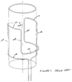
- Figure 3 is a diagram of an "inverted" Helmholtz coil used to generate a radial magnetic field gradient and constructed in accordance with one illustrative embodiment of the invention.
- Figure 4 is a schematic diagram of an RF field generated by a homogeneous coil.
- Figure 5 is a schematic diagram of an RF field generated by a linear magnetic field gradient coil.
- Figure 6 is a schematic diagram of an RF field generated by a radial gradient coil.
- Figure 7 is a schematic diagram of an NMR probe incorporating both a homogeneous probe, a Golay coil and a switching mechanism.
- Figure 8 is a schematic diagram of an NMR probe incorporating both a homogeneous coil, an inverted Helmholtz coil, and a switching mechanism.
- the inventive NMR probe is designed to generate both a homogeneous RF field over the sample volume and, alternatively, a "radial" field comprising two orthogonal gradient fields generated simultaneously in the transverse plane. It is possible to switch rapidly between the two fields by means of a switching mechanism.
- the radial fields are generated by using special RF coils that generate two orthogonal B 1 gradients.
- the differences between the special RF coils used to generate B 1 gradients and the normal homogeneous RF transmitter/receiver coils found in NMR systems can be understood by closely examining both coil types.
- a homogeneous RF coil generates a uniform strength RF field over the entire sample, and, ideally, the uniform strength RF field will also have a uniform phase across the sample.
- An RF coil is generally designed to create an oscillating magnetic field, but as previously mentioned, a nuclear spin system interacts with a rotating magnetic field. However, the oscillating RF field may be thought of as being composed of two rotating fields, one rotating in a one direction and the other counter-rotating in the opposite direction. By convention, the rotating field is defined to be in the same direction as the Larmor rotation direction. Consequently, it is this latter field which interacts with the spin system.
- Figure 1 illustrates schematically the coil windings of a prior art Helmholtz coil design which is useful for generating a homogeneous field.
- the illustrated windings are typically applied over a non-conductive hollow probe body in a conventional manner.
- the probe body has been omitted from Figure 1 to simplify the diagram.
- the arcuate sections (110-116) of the coil subtend an angle of approximately 120°.
- Figure 1 The coil shown in Figure 1 generates a field with a uniform field strength and a phase which is constant over the sample volume as shown in Figure 4.
- Figure 4 is a vector diagram which represents the transverse plane (the nomenclature u and v refer to the transverse plane in the rotating frame) and illustrates that the field is homogeneous within the plane.
- H H ( t ) - B 1 ⁇ cos( ⁇ rf t + ⁇ ) I x + sin( ⁇ rf t + ⁇ ) I y ⁇ which is spatially uniform.
- each of the horizontal arrows represents the local field strength.
- a coil can be designed in accordance with known design principles to generate gradients as follows:
- the above coils are RF coils, the B z component of the RF field is not involved in the generation of the NMR spectrum, so the three above coils generate fields in the transverse plane as follows:
- Option 1 generates two orthogonal gradients, but the gradients do not have equal strength. Therefore, this option will not be considered further.
- Option 3 is closest to being analogous to the well-known B o gradient probe and the coil geometry for this conventional configuration is shown in Figure 2 and called a Golay coil.
- Figure 2 illustrates schematically the coil windings of a prior art Golay coil design which is useful for generating a linear magnetic gradient field. As with the homogeneous field, the illustrated windings are typically applied over a non-conductive hollow probe body in a conventional manner. The probe body has been omitted from Figure 2 to simplify the diagram.
- the connecting wire sections 218 and 220 are arranged so that the fields generated by currents flowing in the wires cancel.
- the coil size is designed so that the arcuate wires 210-216 are sufficiently far from the sample that the fields generated by current flowing in sections 210-216 can be neglected in the vicinity of the sample.
- FIG. 5 A vector picture of the RF field variation across a single channel RF gradient coil constructed in accordance with the Option 3 design is shown in Figure 5.
- the field generated by Option 3 uniformly increases across the sample, and the phase difference between the gradient field produced by the Option 3 coils and a homogeneous field generated by a separate homogeneous coil is uniform across the sample.
- the gradient field can be aligned with the homogeneous field via a software adjustment of the RF phase between RF pulses.
- the Golay coil can be combined with a homogeneous coil and a switching arrangement as described below to form the inventive coil.
- the Golay coil configuration has a relatively high inductance and, as such, is less efficient than other coil configurations.
- An improved design utilizes the radial RF gradient of Option 2. With such a design there is higher efficiency and the probe is capable of generating two orthogonal gradient fields.
- An RF coil constructed in accordance with the Option 2 construction listed above generates a gradient in each of two orthogonal directions. Therefore, every RF pulse that is applied to the probe generates two orthogonal RF gradients, and the nuclear spin system responds to both gradients.
- Figure 3 illustrates schematically the coil windings of an "inverted" Helmholtz coil design constructed in accordance with the principles of the invention which is useful for generating the Option 2 radial field.
- the illustrated windings are typically applied over a non-conductive hollow probe body in a conventional manner.
- the probe body has been omitted from Figure 3 to simplify the diagram.
- the arcuate sections (310-316) of the coil subtend an angle of approximately 90°.
- the coil size is designed so that the arcuate connecting wires 310-316 are sufficiently far from the sample that the fields generated by current flowing in sections 310-316 can be neglected in the vicinity of the sample.
- FIG. 3 The coil shown in Figure 3 generates a field with both a field strength and a phase which vary over the sample volume as shown in Figure 6.
- Figure 6 is a vector diagram which represents the transverse plane (the nomenclature u and v refer to the transverse plane in the rotating frame).
- each of the arrows represents the local field strength.
- FIG 6 not only the strength of the RF field, but also the phase of the RF field is spatially dependent. There are a number of consequences of this spatial dependency:
- the electronic circuits required to drive the coils also differ from the electronics used to drive conventional B o coils, since B o coils are driven with a DC, or near DC, current, whereas, in the RF case, the coil must be driven with high-frequency RF energy.
- the two aforementioned differences cause not only the associated electronics to be very different in the B o and RF gradient cases , but also require changes in the design and construction of the RF coils.
- the RF gradient coil is generally of the same geometry as the B o gradient coil, only a single conductor turn (or a few conductor turns) are employed and self-resonance frequencies, inductances, and inter-winding capacitances, which are not of interest in B o coil construction become important parameters. These latter parameters can, however, be dealt with using conventional and well-known coil construction techniques.
- Figure 7 schematically illustrates a dual coil probe which incorporates both the conventional homogeneous coil 700 with sections 702 and 704 and the Golay coil 706 with sections 708, 710, 712 and 714.
- the coils 700 and 706 are arranged coaxially so that either the homogeneous field or the linear field can be applied to the sample and both coils 700 and 706 are connected to the RF generator 718 by means of a switch 716.
- the switch mechanism 716 used to connect the RF generator to the coils can be any conventional switching arrangement. For example, it is possible to use a physical switch which utilizes high-frequency PIN diodes. However, since the coils 700 and 706 are typically tuned with tuning capacitors to the required resonance frequency, the switching can be effected by simply detuning one or the other of the coils 700 and 706 so that it no longer effectively participates in the interaction.
- Figure 8 schematically illustrates a dual coil probe which incorporates both the conventional homogeneous coil 800 having sections 802 and 804 and the inverted Helmholtz coil 806 with sections 808 and 810.
- the coils 800 and 806 are arranged coaxially so that either the homogeneous field or the radial field and be applied to the sample and both coils 800 and 806 are connected to the RF generator 814 by means of a switch mechanism 812 as described above.
Landscapes
- Physics & Mathematics (AREA)
- Condensed Matter Physics & Semiconductors (AREA)
- General Physics & Mathematics (AREA)
- Magnetic Resonance Imaging Apparatus (AREA)
Claims (6)
- NMR-Probesonde zum Erzeugen von B1-Magnetfeldgradienten in einem Probevolumen aus HF-Energie, die von einem HF-Generator (716,814) erzeugt wird, wobei die Sonde eine erste Helmholtz-Spule (700,800) umfaßt, welche um das Probevolumen herum angeordnet ist und ein Magnetfeld erzeugende Wicklungen (702,704 und 802,804) aufweist, die elektrisch so verbunden sind, daß ein homogenes Magnetfeld in dem Probevolumen erzeugt wird, wenn HF-Energie an die ein Magnetfeld erzeugende Wicklungen (702,704 und 802,804) angelegt wird,
dadurch gekennzeichnet,daß eine zweite Spule (706,806) so ausgebildet ist, daß sie um das Probevolumen herum angeordnet werden kann, wobei die zweite Spule (706,806) ein Magnetfeld erzeugende Wicklungen (708,710,712,714 und 808,810) aufweist, die elektrisch so verbunden sind, daß ein radiales magnetisches Gradientenfeld in dem Probevolumen erzeugt wird, wenn HF-Energie an die ein Magnetfeld erzeugenden Wicklungen (708,710,712,714 und 808,810) angelegt wird; undein HF-Schalter (716,812) zwischen dem HF-Generator (718,814) und der ersten Helmholtz-Spule (700,800) und der zweiten Spule (706,806) angeschlossen ist, um zu ermöglichen, daß entweder die erste Helmholtz-Spule (700,800) oder die zweite Spule (706,806) mit dem HF-Generator (718,814) verbunden wird. - NMR-Sonde nach Anspruch 1, dadurch gekennzeichnet, daß die erste Helmholtz-Spule (700,800) eine Achse und die zweite Spule (706,806) eine Achse hat und die erste Helmholtz-Spule (700,800) und die zweite Spule (706,806) koaxial zueinander angeordnet sind.
- NMR-Sonde nach Anspruch 1 oder 2, dadurch gekennzeichnet, daß der HF-Schalter (718,814) einen HF-PIN-Diodenschalter aufweist.
- NMR-Sonde nach einem der vorhergehenden Ansprüche, dadurch gekennzeichnet, daß die NMR-Sonde zum Durchführen von NMR-Experimenten bei einer Resonanzfrequenz verwendet wird und der HF-Schalter (718,814) eine Einrichtung zum Abstimmen der ersten Helmholtz-Spule und der zweiten Spule auf die Resonanzfrequenz und eine Einrichtung zum selektiven Verstimmen der ersten Helmholtz-Spule (700,800) oder der zweiten Spule (706,806) aufweist.
- NMR-Sonde nach einem der vorhergehenden Ansprüche, dadurch gekennzeichnet, daß die zweite Spule (806) eine Helmholtz-Spule ist.
- NMR-Sonde nach den Ansprüchen 1 bis 4, dadurch gekennzeichnet, daß die zweite Spule (706) eine Golay-Spule ist.
Applications Claiming Priority (2)
| Application Number | Priority Date | Filing Date | Title |
|---|---|---|---|
| US08/030,693 US5323113A (en) | 1993-03-12 | 1993-03-12 | NMR probe which includes B1, gradient coils |
| US30693 | 1993-03-12 |
Publications (2)
| Publication Number | Publication Date |
|---|---|
| EP0615134A1 EP0615134A1 (de) | 1994-09-14 |
| EP0615134B1 true EP0615134B1 (de) | 1998-07-08 |
Family
ID=21855519
Family Applications (1)
| Application Number | Title | Priority Date | Filing Date |
|---|---|---|---|
| EP94103458A Expired - Lifetime EP0615134B1 (de) | 1993-03-12 | 1994-03-08 | Verbesserte NMR-Sonde mit B1-Gradientenspulen |
Country Status (3)
| Country | Link |
|---|---|
| US (1) | US5323113A (de) |
| EP (1) | EP0615134B1 (de) |
| DE (1) | DE69411419T2 (de) |
Families Citing this family (22)
| Publication number | Priority date | Publication date | Assignee | Title |
|---|---|---|---|---|
| US5655533A (en) * | 1994-06-30 | 1997-08-12 | Picker International, Inc. | Actively shielded orthogonal gradient coils for wrist imaging |
| US5914599A (en) * | 1995-08-18 | 1999-06-22 | National Research Council Of Canada | Compensation for inhomogeneity of the field generated by the RF coil in a nuclear magnetic resonance system |
| US5929639A (en) * | 1996-07-03 | 1999-07-27 | Doty Scientific Inc. | Non-dipolar RF coil for NMR lock and homonuclear decoupling |
| AU3007300A (en) | 1999-02-26 | 2000-09-14 | Purdue Research Foundation | Nuclear magnetic resonance analysis of multiple samples |
| EP1295144A1 (de) * | 2000-06-15 | 2003-03-26 | Koninklijke Philips Electronics N.V. | Bildgebende magnetische resonanz mit unterabtastung |
| US6369570B1 (en) | 2000-12-21 | 2002-04-09 | Varian, Inc. | B1 gradient coils |
| US6552544B2 (en) * | 2001-04-05 | 2003-04-22 | Varian, Inc. | Detunable coil assembly and method of detuning RF coil for MRI |
| US6590392B2 (en) * | 2001-04-17 | 2003-07-08 | Ge Medical Systems Global Technology Co., Llc | Switchable FOV coil assembly having end saddle coils |
| US7906966B1 (en) | 2001-10-05 | 2011-03-15 | Fonar Corporation | Quadrature foot coil antenna for magnetic resonance imaging |
| US7701209B1 (en) | 2001-10-05 | 2010-04-20 | Fonar Corporation | Coils for horizontal field magnetic resonance imaging |
| US7221161B2 (en) * | 2003-01-21 | 2007-05-22 | General Electric Company | Coil arrays for parallel imaging in magnetic resonance imaging |
| US20040158144A1 (en) * | 2003-02-03 | 2004-08-12 | Topshooter Medical Imri Inc. | NMR probe particularly useful for intra-luminal imaging |
| JP4105646B2 (ja) * | 2004-03-02 | 2008-06-25 | 株式会社日立製作所 | 核磁気共鳴装置 |
| US8401615B1 (en) | 2004-11-12 | 2013-03-19 | Fonar Corporation | Planar coil flexion fixture for magnetic resonance imaging and use thereof |
| EP2030035A2 (de) * | 2006-05-30 | 2009-03-04 | Philips Intellectual Property & Standards GmbH | Verstimmen einer hochfrequenzspule |
| US9386939B1 (en) | 2007-05-10 | 2016-07-12 | Fonar Corporation | Magnetic resonance imaging of the spine to detect scoliosis |
| US7446532B1 (en) * | 2007-07-18 | 2008-11-04 | Varian, Inc. | Arched saddle-shaped NMR RF coils |
| US8599215B1 (en) | 2008-05-07 | 2013-12-03 | Fonar Corporation | Method, apparatus and system for joining image volume data |
| US9766310B1 (en) | 2013-03-13 | 2017-09-19 | Fonar Corporation | Method and apparatus for magnetic resonance imaging of the cranio-cervical junction |
| BR112019003016B1 (pt) * | 2016-09-20 | 2022-09-27 | Halliburton Energy Services, Inc | Ferramenta de perfilagem de ressonância magnética nuclear, e, métodos de perfilagem de ressonância magnética nuclear |
| WO2018081626A1 (en) | 2016-10-28 | 2018-05-03 | The United States Of America, As Represented By The Secretary, Department Of Health And Human Services | Stable water isotope labeling and magnetic resonance imaging for visualization of rapidly dividing cells |
| CH715259A1 (de) * | 2018-08-16 | 2020-02-28 | Wilco Ag | Verfahren und Vorrichtung zur Inspektion eines Zustands einer auf einer Spritze aufgesetzten Kanüle. |
Family Cites Families (10)
| Publication number | Priority date | Publication date | Assignee | Title |
|---|---|---|---|---|
| GB1596160A (en) * | 1976-12-15 | 1981-08-19 | Nat Res Dev | Nuclear magnetic resonance apparatus and methods |
| JPS58223048A (ja) * | 1982-06-21 | 1983-12-24 | Toshiba Corp | 磁気共鳴励起領域選択方法、および、該方法が実施し得る磁気共鳴イメージング装置 |
| JPS5940843A (ja) * | 1982-08-31 | 1984-03-06 | 株式会社東芝 | 診断用核磁気共鳴装置 |
| EP0365065B1 (de) * | 1985-09-20 | 2003-03-12 | Btg International Limited | Magnetfeldschirme |
| US4899109A (en) * | 1988-08-17 | 1990-02-06 | Diasonics Inc. | Method and apparatus for automated magnetic field shimming in magnetic resonance spectroscopic imaging |
| EP0426851B1 (de) * | 1988-10-07 | 1997-01-02 | Hitachi, Ltd. | Vorrichtung zum nachweis von teilchen |
| US5015954A (en) * | 1989-06-30 | 1991-05-14 | Auburn International, Inc. | Magnetic resonance analysis in real time, industrial usage mode |
| US5049819A (en) * | 1989-06-30 | 1991-09-17 | Auburn International, Inc. | Magnetic resonance analysis in real time, industrial usage mode |
| DE4024834A1 (de) * | 1990-08-04 | 1992-02-27 | Bruker Analytische Messtechnik | Nqr-bildgebungsverfahren |
| US5150052A (en) * | 1991-02-15 | 1992-09-22 | Meyerand Mary E | Apparatus and method for magnetic resonance spectral imaging |
-
1993
- 1993-03-12 US US08/030,693 patent/US5323113A/en not_active Expired - Lifetime
-
1994
- 1994-03-08 EP EP94103458A patent/EP0615134B1/de not_active Expired - Lifetime
- 1994-03-08 DE DE69411419T patent/DE69411419T2/de not_active Expired - Lifetime
Also Published As
| Publication number | Publication date |
|---|---|
| EP0615134A1 (de) | 1994-09-14 |
| US5323113A (en) | 1994-06-21 |
| DE69411419D1 (de) | 1998-08-13 |
| DE69411419T2 (de) | 1999-04-15 |
Similar Documents
| Publication | Publication Date | Title |
|---|---|---|
| EP0615134B1 (de) | Verbesserte NMR-Sonde mit B1-Gradientenspulen | |
| Hoult | Solvent peak saturation with single phase and quadrature Fourier transformation | |
| US5485086A (en) | Continuous fluoroscopic MRI using spiral k-space scanning | |
| RU2344411C2 (ru) | Способ, чувствительные элементы и система для обнаружения и/или анализа соединений, одновременно проявляющих ядерный квадрупольный резонанс и ядерно-магнитный резонанс или двойной ядерный квадрупольный резонанс | |
| JPH0693010B2 (ja) | 軸方向の磁界均質性を改良したnmr無線周波コイル | |
| EP0347990B1 (de) | Verfahren und Anordnung zum volumeselektiven Bestimmen eines Kernspinresonanz-spectrums mittels selektiver Polarisationsübertragungs-Impulsfolgen | |
| US4947119A (en) | Magnetic resonance imaging and spectroscopy methods | |
| US20030088181A1 (en) | Method of localizing an object in an MR apparatus, a catheter and an MR apparatus for carrying out the method | |
| US5539315A (en) | NMR probe for cross-polarization measurements | |
| US6825660B2 (en) | Degenerate birdcage resonator for magnetic resonance imaging | |
| JPH0820496B2 (ja) | Nmr磁界コイルを同調させる方法 | |
| EP0209374B1 (de) | Phasenkodierung bei der magnetischen Kernresonanz mit in der Phase varierenden Hochfrequenzimpulsen | |
| WO2006028588A2 (en) | Nuclear magnetic resonance detection in inhomogeneous magnetic fields | |
| Demco et al. | Spatially resolved homonuclear solid-state NMR. III. Magic-echo and rotary-echo phase-encoding imaging | |
| US20140218025A1 (en) | Transverse volume coils and related magnetic resonance systems and methods | |
| US5872452A (en) | Apparatus and method for the generation of gradient magnetic fields for high resolution NMR experiments | |
| US5260656A (en) | Method for improving the resolution of solid-state NMR multiple-pulse imaging systems | |
| US5546000A (en) | Method for the reduction of radiation damping during signal acqusition in NMR experiments | |
| US4707659A (en) | Method and device for determining an NMR distribution in a region of a body | |
| US5208536A (en) | Method for slice selection in an NMR MAS solids imaging system | |
| Miller et al. | Circularly polarized RF magnetic fields for spin-1 NQR | |
| USH1218H (en) | NMR imaging with varying spatial coupling | |
| US5532594A (en) | Method for suppressing solvent resonance signals in NMR experiments | |
| US5280245A (en) | Magnetic resonance apparatus employing delayed self-refocusing RF excitation | |
| GB2105853A (en) | Spatially selective NMR |
Legal Events
| Date | Code | Title | Description |
|---|---|---|---|
| PUAI | Public reference made under article 153(3) epc to a published international application that has entered the european phase |
Free format text: ORIGINAL CODE: 0009012 |
|
| AK | Designated contracting states |
Kind code of ref document: A1 Designated state(s): CH DE FR GB LI |
|
| 17P | Request for examination filed |
Effective date: 19940909 |
|
| GRAG | Despatch of communication of intention to grant |
Free format text: ORIGINAL CODE: EPIDOS AGRA |
|
| GRAG | Despatch of communication of intention to grant |
Free format text: ORIGINAL CODE: EPIDOS AGRA |
|
| GRAH | Despatch of communication of intention to grant a patent |
Free format text: ORIGINAL CODE: EPIDOS IGRA |
|
| 17Q | First examination report despatched |
Effective date: 19970929 |
|
| GRAH | Despatch of communication of intention to grant a patent |
Free format text: ORIGINAL CODE: EPIDOS IGRA |
|
| GRAA | (expected) grant |
Free format text: ORIGINAL CODE: 0009210 |
|
| AK | Designated contracting states |
Kind code of ref document: B1 Designated state(s): CH DE FR GB LI |
|
| PG25 | Lapsed in a contracting state [announced via postgrant information from national office to epo] |
Ref country code: FR Free format text: LAPSE BECAUSE OF FAILURE TO SUBMIT A TRANSLATION OF THE DESCRIPTION OR TO PAY THE FEE WITHIN THE PRESCRIBED TIME-LIMIT Effective date: 19980708 |
|
| REG | Reference to a national code |
Ref country code: CH Ref legal event code: EP |
|
| REF | Corresponds to: |
Ref document number: 69411419 Country of ref document: DE Date of ref document: 19980813 |
|
| REG | Reference to a national code |
Ref country code: CH Ref legal event code: NV Representative=s name: ISLER & PEDRAZZINI AG |
|
| EN | Fr: translation not filed | ||
| PLBE | No opposition filed within time limit |
Free format text: ORIGINAL CODE: 0009261 |
|
| STAA | Information on the status of an ep patent application or granted ep patent |
Free format text: STATUS: NO OPPOSITION FILED WITHIN TIME LIMIT |
|
| 26N | No opposition filed | ||
| REG | Reference to a national code |
Ref country code: GB Ref legal event code: IF02 |
|
| REG | Reference to a national code |
Ref country code: CH Ref legal event code: PCAR Free format text: ISLER & PEDRAZZINI AG;POSTFACH 1772;8027 ZUERICH (CH) |
|
| PGFP | Annual fee paid to national office [announced via postgrant information from national office to epo] |
Ref country code: CH Payment date: 20130322 Year of fee payment: 20 Ref country code: GB Payment date: 20130321 Year of fee payment: 20 Ref country code: DE Payment date: 20130321 Year of fee payment: 20 |
|
| REG | Reference to a national code |
Ref country code: DE Ref legal event code: R071 Ref document number: 69411419 Country of ref document: DE |
|
| REG | Reference to a national code |
Ref country code: CH Ref legal event code: PL |
|
| REG | Reference to a national code |
Ref country code: GB Ref legal event code: PE20 Expiry date: 20140307 |
|
| PG25 | Lapsed in a contracting state [announced via postgrant information from national office to epo] |
Ref country code: GB Free format text: LAPSE BECAUSE OF EXPIRATION OF PROTECTION Effective date: 20140307 Ref country code: DE Free format text: LAPSE BECAUSE OF EXPIRATION OF PROTECTION Effective date: 20140311 |