EP0614429B1 - Method for producing a trolley made of a synthetic material - Google Patents
Method for producing a trolley made of a synthetic material Download PDFInfo
- Publication number
- EP0614429B1 EP0614429B1 EP92923784A EP92923784A EP0614429B1 EP 0614429 B1 EP0614429 B1 EP 0614429B1 EP 92923784 A EP92923784 A EP 92923784A EP 92923784 A EP92923784 A EP 92923784A EP 0614429 B1 EP0614429 B1 EP 0614429B1
- Authority
- EP
- European Patent Office
- Prior art keywords
- manufacturing
- basket
- moulded
- cart
- flank
- Prior art date
- Legal status (The legal status is an assumption and is not a legal conclusion. Google has not performed a legal analysis and makes no representation as to the accuracy of the status listed.)
- Expired - Lifetime
Links
- 238000004519 manufacturing process Methods 0.000 title claims abstract description 36
- 229920002994 synthetic fiber Polymers 0.000 title claims abstract description 8
- 238000000034 method Methods 0.000 claims description 20
- 238000000465 moulding Methods 0.000 claims description 16
- 238000000605 extraction Methods 0.000 claims description 3
- 230000008878 coupling Effects 0.000 claims 5
- 238000010168 coupling process Methods 0.000 claims 5
- 238000005859 coupling reaction Methods 0.000 claims 5
- 238000005304 joining Methods 0.000 description 7
- 239000003677 Sheet moulding compound Substances 0.000 description 5
- 239000000463 material Substances 0.000 description 5
- 230000006835 compression Effects 0.000 description 3
- 238000007906 compression Methods 0.000 description 3
- 238000005452 bending Methods 0.000 description 2
- 238000010276 construction Methods 0.000 description 2
- 239000002184 metal Substances 0.000 description 2
- 238000003860 storage Methods 0.000 description 2
- 239000004593 Epoxy Substances 0.000 description 1
- 238000010521 absorption reaction Methods 0.000 description 1
- 238000004026 adhesive bonding Methods 0.000 description 1
- 239000002131 composite material Substances 0.000 description 1
- 238000005520 cutting process Methods 0.000 description 1
- 238000006073 displacement reaction Methods 0.000 description 1
- 239000003365 glass fiber Substances 0.000 description 1
- 210000002445 nipple Anatomy 0.000 description 1
- 239000004033 plastic Substances 0.000 description 1
- 238000003825 pressing Methods 0.000 description 1
- 230000001681 protective effect Effects 0.000 description 1
- 230000002787 reinforcement Effects 0.000 description 1
- 230000035939 shock Effects 0.000 description 1
- 239000007787 solid Substances 0.000 description 1
Images


Classifications
-
- B—PERFORMING OPERATIONS; TRANSPORTING
- B62—LAND VEHICLES FOR TRAVELLING OTHERWISE THAN ON RAILS
- B62B—HAND-PROPELLED VEHICLES, e.g. HAND CARTS OR PERAMBULATORS; SLEDGES
- B62B3/00—Hand carts having more than one axis carrying transport wheels; Steering devices therefor; Equipment therefor
- B62B3/14—Hand carts having more than one axis carrying transport wheels; Steering devices therefor; Equipment therefor characterised by provisions for nesting or stacking, e.g. shopping trolleys
-
- B—PERFORMING OPERATIONS; TRANSPORTING
- B62—LAND VEHICLES FOR TRAVELLING OTHERWISE THAN ON RAILS
- B62B—HAND-PROPELLED VEHICLES, e.g. HAND CARTS OR PERAMBULATORS; SLEDGES
- B62B2501/00—Manufacturing; Constructional features
- B62B2501/06—Materials used
- B62B2501/065—Plastics
Definitions
- the method according to the invention can be used for the manufacture of any type of trolleys intended for use in self-service stores.
- the process can thus be used for the manufacture of basket trolleys both at great and at shallow depth.
Landscapes
- Engineering & Computer Science (AREA)
- Chemical & Material Sciences (AREA)
- Combustion & Propulsion (AREA)
- Transportation (AREA)
- Mechanical Engineering (AREA)
- Handcart (AREA)
- Processing And Handling Of Plastics And Other Materials For Molding In General (AREA)
- Shaping Of Tube Ends By Bending Or Straightening (AREA)
- Ropes Or Cables (AREA)
- Treatments Of Macromolecular Shaped Articles (AREA)
- Moulding By Coating Moulds (AREA)
- Load-Engaging Elements For Cranes (AREA)
Abstract
Description
L'invention concerne un procédé de fabrication d'un chariot en matière synthetique, en particulier un chariot destiné à usage dans des magasins en libre-service, ledit chariot ayant un premier et un second flanc latéral qui comportent chacun un segment de pied et un segment de panier moulés en une seule pièce, lesdits premier et second flancs latéraux étant reliés entre eux à l'aide d'éléments de jonction.The invention relates to a method for manufacturing a trolley made of synthetic material, in particular a trolley intended for use in self-service shops, said trolley having first and second lateral flanks each comprising a foot segment and a basket segment molded in one piece, said first and second lateral flanks being interconnected by means of joining elements.
Un tel procédé de fabrication est connu du brevet US-A-3.614.133. Le chariot connu est formé à partir de deux flancs latéraux identiques. Le segment de panier de chaque flanc latéral est constitué d'un bras qui s'étend à partir du segment de pied vers le haut, c'est-à-dire vers l'endroit où se trouve la poignée. Le segment de pied possède une configuration en épingle à cheveux renforcée par un support central. Un premier grillage est monté sur le bras supérieur de la configuration en épingle à cheveux, ledit grillage est également fixé sur le segment de panier. Les premiers grillages montés sur les flancs latéraux sont reliés entre eux à l'aide de deuxièmes grillages formant les flancs transversaux du panier. L'assemblage des différents composants est réalisé à l'aide de barres munies d'un pas de vis et de boulons.Such a manufacturing process is known from US-A-3,614,133. The known carriage is formed from two identical lateral flanks. The basket segment of each lateral flank consists of an arm which extends from the foot segment upwards, that is to say towards the place where the handle is located. The foot segment has a hairpin configuration reinforced by a central support. A first screen is mounted on the upper arm of the hairpin configuration, said screen is also fixed on the basket segment. The first grids mounted on the lateral flanks are interconnected by means of second grids forming the transverse flanks of the basket. The various components are assembled using bars fitted with a thread and bolts.
Un désavantage du chariot obtenu par le procédé connu est qu'une grande partie du panier se trouve en porte-à-faux, ladite partie étant uniquement soutenue par le bras supérieur de ladite configuration en épingle à cheveux. Ce même bras doit également soutenir le premier grillage. Cette construction, conjuguée au fait que le premier grillage est encore relié en un point supérieur du segment de panier, n'assure pas une stabilité suffisante du chariot et peut provoquer un basculement, vers l'avant, du chariot lorsque trop de poids est mis à l'avant du chariot. Pour palier à ce problème, le chariot connu comporte un support central. Toutefois, la présence de ce support central limite l'emboîtement des chariots l'un dans l'autre, ce qui, à son tour, impose une plus grande surface de rangement du parc de chariot.A disadvantage of the carriage obtained by the known method is that a large part of the basket is in overhang, said part being only supported by the upper arm of said hairpin configuration. This same arm must also support the first fence. This construction, combined with the fact that the first grid is still connected at an upper point of the basket segment, does not ensure sufficient stability of the carriage and can cause the carriage to tilt forwards when too much weight is placed at the front of the cart. To overcome this problem, the known carriage has a central support. However, the presence of this central support limits the nesting of the carriages one inside the other, which, in turn, imposes a larger storage area of the fleet of trolleys.
L'invention a pour but de réaliser un procédé de fabrication d'un chariot permettant d'obtenir un chariot ayant une plus grande stabilité sans limiter les possibilités d'emboîtement.The object of the invention is to provide a method of manufacturing a carriage making it possible to obtain a carriage having greater stability without limiting the possibilities of nesting.
A cette fin, un procédé suivant l'invention est caractérisé en ce que, lors du moulage des flancs latéraux, on moule en une seule pièce au moins le contour latéral du segment de panier ainsi qu'un premier resp. un second rebord sur le premier resp. le second flanc latéral, lesdits premier et second rebords étant moulés de telle façon qu'ils s'étendent en une direction opposée l'une à l'autre lorsque le chariot est assemblé, lesdits premier et second flancs étant assemblés à l'aide des éléments de jonction qui s'appliquent sur lesdits rebords. Puisque au moins le contour latéral du segment de panier et un rebord sont moulés d'une seule pièce avec le flanc latéral du chariot, on obtient une structure plus rigide du flanc latéral. Cette structure plus rigide permet de mieux absorber les forces exercées par des objets posés dans le panier et donc de donner une meilleure stabilité au chariot. Eu égard au fait que le contour latéral du segment de panier fait partie intégrante du flanc latéral, une force appliquée même sur la partie avant du panier est répartie sur l'ensemble du chariot. Un meilleur équilibre du chariot est ainsi obtenu, sans devoir faire appel à des éléments de renforcement qui limitent l'emboîtement. La présence des rebords permet non seulement de rigidifier la structure du chariot mais offre également un moyen approprié pour un assemblage rapide et fiable.To this end, a method according to the invention is characterized in that, during the molding of the lateral flanks, at least the lateral contour of the basket segment is molded in one piece as well as a first resp. a second ledge on the first resp. the second lateral flank, said first and second flanges being molded such that they extend in a direction opposite to each other when the carriage is assembled, said first and second flanks being assembled using joining elements which are applied on said edges. Since at least the lateral contour of the basket segment and a rim are molded in one piece with the lateral flank of the carriage, a more rigid structure of the lateral flank is obtained. This more rigid structure allows better absorption of the forces exerted by objects placed in the basket and therefore gives better stability to the cart. In view of the fact that the lateral contour of the basket segment is an integral part of the lateral flank, a force applied even on the front part of the basket is distributed over the entire carriage. A better balance of the carriage is thus obtained, without having to call upon elements of reinforcement which limit nesting. The presence of the edges not only makes it possible to stiffen the structure of the carriage but also offers an appropriate means for rapid and reliable assembly.
De plus, puisque le flanc latéral et le segment de pied forment un ensemble, il est possible par la géométrie de l'ensemble de limiter sensiblement la flexion grâce au fait que l'ensemble flanc latéral-pied est moulé en une seule pièce, il est également possible d'utiliser des moules à faible empreinte du moins en ce qui concerne la profondeur. L'emploi d'éléments de jonction qui s'appliquent sur les rebords permet d'utiliser les mêmes dimensions de flanc et donc le même moule pour obtenir différentes dimensions de chariot. Puisque ces éléments de jonction sont simples à fabriquer et n'exigent pas de moules à grandes empreintes, leur emploi permet de réduire sensiblement les investissements dans les moules et donc les frais de fabrication. Le choix particulier et judicieux dans la fabrication des différents composants du chariot permet donc non seulement de fabriquer un chariot plus solide et plus résistant mais également de le fabriquer à un coût sensiblement réduit.In addition, since the lateral flank and the foot segment form an assembly, it is possible by the geometry of the assembly to significantly limit the flexion thanks to the fact that the lateral flank-foot assembly is molded in one piece, it it is also possible to use molds with a small footprint at least as far as depth is concerned. The use of junction elements which are applied on the flanges allows the same flank dimensions and therefore the same mold to be used to obtain different carriage dimensions. Since these junction elements are simple to manufacture and do not require large footprint molds, their use makes it possible to significantly reduce investment in molds and therefore manufacturing costs. The particular and judicious choice in the manufacture of the various components of the trolley therefore makes it possible not only to manufacture a more solid and more resistant trolley but also to manufacture it at a substantially reduced cost.
Une première forme de réalisation préférentielle d'un procédé suivant l'invention est caractérisée en ce que les flancs latéraux sont moulés à une dimension prédéterminée, un jeu d'éléments de jonction étant moulé pour chaque dimension des flancs latéraux, les différents éléments dudit jeu ayant chacun une largeur prédéterminée différente l'une de l'autre. Ceci permet une construction modulaire du chariot. En partant d'une même dimension des flancs latéraux, on peut ainsi construire des chariots de différents volumes simplement en utilisant des éléments de jonction de différentes largeurs. Le coût de production de chariot de différents volumes s'en trouve ainsi réduit.A first preferred embodiment of a method according to the invention is characterized in that the lateral flanks are molded to a predetermined dimension, a set of joining elements being molded for each dimension of the lateral flanks, the different elements of said set each having a predetermined width different from each other. This allows modular construction of the cart. Starting from the same dimension of the lateral sides, it is thus possible to build carriages of different volumes simply by using joining elements of different widths. The cost of producing trolleys of different volumes is thereby reduced.
Une deuxième forme de réalisation préférentielle d'un procédé suivant l'invention est caractérisée en ce qu'au moins une ouverture est moulée dans le segment de panier de chaque flanc latéral. Grâce à la technique de moulage des flancs latéraux, il est possible d'y appliquer facilement une ouverture, puisque le pressage se fait verticalement par rapport au plan du flanc. Ainsi sans faire appel à des moules chers à fabriquer, il est possible d'y appliquer à moindre frais des ouvertures dans les flancs latéraux, sans porter atteinte à la rigidité du chariot.A second preferred embodiment of a method according to the invention is characterized in that at least one opening is molded in the basket segment of each lateral flank. Thanks to the sidewall molding technique, it is possible to easily apply an opening, since the pressing is done vertically with respect to the plane of the sidewall. Thus, without using expensive molds to manufacture, it is possible to apply openings in the lateral flanks at a lower cost, without affecting the rigidity of the carriage.
De préférence un grillage est appliqué dans chacune desdites ouvertures. Ceci donne un aspect bien connu au chariot.Preferably a mesh is applied in each of said openings. This gives a well-known appearance to the cart.
De préférence, deux ouvertures essentiellement triangulaires sont prévues dans chaque flanc latéral, lesdites ouvertures étant séparées par une branche qui s'étend en diagonale dans ledit flanc à partir d'une partie frontale supérieure vers une partie arrière inférieure du chariot. La présence de la branche diagonale permet de rigidifier davantage le chariot.Preferably, two essentially triangular openings are provided in each lateral flank, said openings being separated by a branch which extends diagonally in said flank from an upper front part towards a lower rear part of the carriage. The presence of the diagonal branch allows to further stiffen the carriage.
Une troisième forme de réalisation préférentielle d'un procédé suivant l'invention est caractérisée en ce qu'au moins un point de fixation d'une poignée est moulé simultanément avec le moulage dudit flanc latéral. Ces points de fixation forment ainsi un ensemble avec le flanc latéral, ce qui facilite la fabrication et permet de former une fixation rigide.A third preferred embodiment of a method according to the invention is characterized in that at least one attachment point of a handle is molded simultaneously with the molding of said lateral flank. These attachment points thus form an assembly with the lateral flank, which facilitates manufacture and makes it possible to form a rigid attachment.
Une quatrième forme de réalisation préférentielle d'un procédé suivant l'invention est caractérisée en ce qu'un volet pourvu d'une saillie ayant une longueur correspondant à celle de la distance entre les bossages est monté contre la porte de telle façon que les bossages et la saillie forment une charnière. Ceci permet d'assurer une bonne fixation du volet au chariot, lequel volet peut alors servir en tant que siège d'enfant.A fourth preferred embodiment of a method according to the invention is characterized in that a flap provided with a projection having a length corresponding to that of the distance between the bosses is mounted against the door in such a way that the bosses and the projection form a hinge. This ensures good fixing of the shutter to the carriage, which flap can then be used as a child seat.
Une cinquième forme de réalisation préférentielle d'un procédé suivant l'invention est caractérisée en ce qu'un rail de guidage est moulé sur chaque flanc latéral en un endroit situé sous le fond du panier et en ce qu'après avoir réuni les flancs latéraux, une tablette coulissante est montée entre les rails de guidage. La tablette peut ainsi glisser dans le rail et permet d'y poser des objets sans devoir les lever trop haut, ce qui est surtout un avantage pour des objets lourds et rend l'utilisation d'un tel chariot plus attrayant pour des personnes ayant quelque peine à soulever de tels objets.A fifth preferred embodiment of a method according to the invention is characterized in that a guide rail is molded on each lateral flank in a place situated under the bottom of the basket and in that after having united the lateral flanks , a sliding shelf is mounted between the guide rails. The tablet can thus slide in the rail and allows objects to be placed there without having to lift them too high, which is especially an advantage for heavy objects and makes the use of such a trolley more attractive for people with some barely lift such objects.
De préférence, une autre ouverture est appliquée dans l'élément de jonction servant à relier à leur partie avant les flancs latéraux, une languette d'extraction étant montée à un bord transversal de ladite ouverture. Ceci permet d'introduire facilement un panneau publicitaire dans ou devant l'autre ouverture.Preferably, another opening is applied in the junction element serving to connect the front sides to their front part, an extraction tab being mounted at a transverse edge of said opening. This allows an advertising panel to be easily inserted into or in front of the other opening.
De préférence, les éléments du chariot sont fabriqués en SMC. Le SMC est un matériau léger qui résiste bien aux chocs, ce qui le rend parfaitement apte à la fabrication du chariot.Preferably, the elements of the trolley are made of SMC. SMC is a light material which resists shocks well, which makes it perfectly suitable for manufacturing the trolley.
L'invention sera maintenant décrite plus en détail à l'aide de dessins qui illustrent des exemples d'un chariot fabriqué par l'application du procédé suivant l'invention.The invention will now be described in more detail with the aid of drawings which illustrate examples of a carriage produced by the application of the method according to the invention.
Dans les dessins :
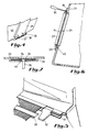
- La figure 1 illustre une vue explosée d'un exemple de chariot fabriqué par application du procédé suivant l'invention.
- La figure 2 illustre en détail un flanc latéral d'un chariot suivant l'invention.
- La figure 3 montre un autre exemple, également en vue explosée, d'un chariot suivant l'invention.
- La figure 4 illustre un détail d'une porte pourvue d'un volet.
- La figure 5 illustre le montage d'une tablette coulissante sur un chariot suivant l'invention.
- La figure 6 montre l'application d'un panneau publicitaire sur un chariot suivant l'invention.
- La figure 7 illustre une partie du panneau publicitaire.
- FIG. 1 illustrates an exploded view of an example of a cart manufactured by applying the method according to the invention.
- FIG. 2 illustrates in detail a lateral flank of a carriage according to the invention.
- Figure 3 shows another example, also in exploded view, of a carriage according to the invention.
- Figure 4 illustrates a detail of a door provided with a flap.
- FIG. 5 illustrates the mounting of a sliding shelf on a trolley according to the invention.
- Figure 6 shows the application of an advertising panel on a cart according to the invention.
- Figure 7 illustrates part of the advertising panel.
Dans les dessins, une même référence a été assignée aux mêmes éléments ou à des éléments analogues.In the drawings, the same reference has been assigned to the same or similar elements.
La matière synthétique dans laquelle est fabriqué le chariot est de préférence le SMC (Sheet Molding Compound). Cette matière synthétique est entre autres utilisée pour la fabrication de pare-chocs d'automobiles et a l'avantage d'être très résistant aux chocs, facile à mouler et peu onéreuse. De plus, cette matière est pratiquement entièrement recyclable. Le moulage des différents composants du chariot se fait de préférence par compression, mais il va de soi que d'autres techniques de fabrication sont également applicables. Mis à part le composite SMC, d'autres matières synthétiques, telles que par exemple de l'époxy renforcé par des fibres de verre, peuvent être utilisées.The synthetic material from which the carriage is made is preferably SMC (Sheet Molding Compound). This synthetic material is used inter alia for the manufacture of automobile bumpers and has the advantage of being very impact resistant, easy to mold and inexpensive. In addition, this material is almost entirely recyclable. The molding of the various components of the carriage is preferably done by compression, but it goes without saying that other manufacturing techniques are also applicable. Apart from the SMC composite, other synthetic materials, such as for example glass fiber reinforced epoxy, can be used.
La figure 1 illustre une vue explosée d'un premier exemple d'un chariot fabriqué par application du procédé suivant l'invention. Le chariot comporte un premier 1 respectivement un second 3 flanc latéral. Chaque flanc latéral comporte un rebord 12, 13, qui s'étend sur tout le périmètre formé par la cuve du panier. Le rebord 12 du premier flanc 1 latéral et le rebord 13 du second 3 flanc latéral sont moulés de telle façon qu'ils s'étendent en une direction opposée l'un à l'autre lorsque le chariot est assemblé. Le pied du chariot comporte deux segments 2, 4 qui forment chacun un ensemble avec leur flanc latéral respectif. Comme illustré en détail à la figure 2, le segment de pied 2 et le flanc latéral 1 sont moulés en une seule pièce. Grâce à ceci, on obtient une liaison très rigide entre le segment de pied 2 et le flanc latéral 1.FIG. 1 illustrates an exploded view of a first example of a carriage manufactured by applying the method according to the invention. The carriage comprises a first 1 respectively a second 3 lateral flank. Each lateral flank has a
Le segment de pied 2 comporte une première 19, une deuxième 20 et une troisième 21 partie qui sont moulées en une seule pièce. La première partie 19 comporte une géométrie sensiblement en épingle à cheveux, ce qui permet de bien absorber la flexion imposée par le panier, lorsque ce dernier est rempli. L'inclinaison de la deuxième partie 20 ainsi que l'inclinaison du fond du panier permettent l'emboîtement des chariots lors de leur rangement. La troisième partie 21 forme un rebord qui sert à l'assemblage des différentes parties, comme expliqué ci-dessous.The
Comme mentionné ci-dessus, le segment de pied et le flanc latéral sont moulés en une seule pièce. Comme on peut le constater dans les figures 1 et 2, l'épaisseur du flanc, de son rebord et du segment de pied, est peu élevée. Ceci permet d'utiliser pour le moulage des composants du chariot un moule (poinçon/matrice) à faible empreinte, par exemple 150 mm. De tels moules sont sensiblement moins onéreux que ceux à forte empreinte. Lors du moulage, la compression se fait dans un sens qui est perpendiculaire (moulage à plat) au plan formé par le flanc latéral. Ainsi, la compression ne nécessite pas un grand déplacement du poinçon, ce qui entraînera une cadence de production plus élevée et donc moins onéreuse.As mentioned above, the foot segment and the sidewall are molded in one piece. As can be seen in Figures 1 and 2, the thickness of the sidewall, its rim and the foot segment is small. This makes it possible to use a mold (punch / die) with a small footprint, for example 150 mm, for molding the components of the carriage. Such molds are significantly less expensive than those with a large footprint. During molding, compression takes place in a direction which is perpendicular (flat molding) to the plane formed by the lateral flank. Thus, compression does not require a large displacement of the punch, which will result in a higher production rate and therefore less expensive.
Les flancs étant moulés à plat, il est maintenant possible d'appliquer lors du moulage des ouvertures latérales 8 et 9 dans le flanc du panier, permettant d'obtenir une vision de l'extérieur vers l'intérieur du panier. Il va de soi que le nombre de deux ouvertures n'est qu'un choix et que d'autres alternatives peuvent également être envisagées. De préférence, un grillage 10, 11 est monté dans les ouvertures 8, 9. Ces grillages sont de préférence fabriqués par moulage dans la même matière que celle du flanc latéral. Ils peuvent être soit moulés simultanément avec le moulage du flanc, soit séparément et ensuite collés dans les ouvertures. L'utilisation de grillage donne ainsi un aspect bien connu au chariot. Mais il va de soi que les grillages peuvent également être réalisés en d'autres matières que celle utilisée pour le flanc, comme par exemple en ABS injecté.The sides being molded flat, it is now possible to apply during
De préférence, les ouvertures 8 et 9 sont séparées par une branche 47 qui s'étend en diagonale dans ledit flanc. La branche 47 part du fond du panier du côté arrière du chariot, vers une partie frontale supérieure. La branche possède de préférence une largeur qui s'accroît en direction du fond du panier. La présence de cette branche permet non seulement de délimiter en partie le contour des ouvertures 8 et 9, mais également de rigidifier le flanc latéral. La branche 47 est bien entendu moulée d'une seule pièce avec le flanc latéral.Preferably, the
Chaque flanc latéral est muni d'un point de fixation 5, également moulé en une seule pièce avec le flanc latéral auquel il est adjoint. Ce point de fixation sert à y fixer une poignée 6, par exemple à l'aide d'une vis 7 ou par collage de la poignée au point de fixation.Each lateral flank is provided with a
Chaque segment de pied est muni de petites roues 14, 15 fixées à l'aide d'organes de fixation appropriés 16, 17 à la partie inférieure du pied comme illustré à la figure 2.Each foot segment is provided with
Chaque flanc latéral comporte de préférence également un encastrement 18 appliqué dans une protubérance. Cet encastrement sert à y loger un téton 14 d'une porte 40 du chariot.Each lateral flank preferably also includes a
La porte est de préférence également pourvue d'ouvertures dans lesquelles sont appliqués des grillages 41. Grâce à l'utilisation du téton 14 et de l'encastrement 18, la porte peut basculer vers l'intérieur du panier afin de permettre l'emboîtement des chariots. De préférence, une pièce commutable 42 est glissée sur chaque téton 14 lors du montage de la porte. L'emploi de cette pièce commutable permet de limiter la friction du téton à l'intérieur de la protubérance.The door is preferably also provided with openings in which gratings 41 are applied. Thanks to the use of the
Les troisièmes parties 21 de chaque segment de pied 2 et 4 sont reliées entre elles à l'aide d'une jupe 20 qui s'engage dans ces troisièmes parties. La jupe 43 est de préférence collée aux premières parties 11. Cette jupe est de préférence également fabriquée par moulage comme les autres composants du chariot.The
Les rebords 12 et 13 de chaque flanc sont reliés par un longeron de fond 39, qui, de préférence, a la forme d'un T permettant ainsi l'application du grillage dans le fond du panier. Le longeron de fond 39 est de préférence collé aux rebords 12 et 13.The
Les extrémités avant des deuxièmes parties 20 du segment de pied sont reliées entre elles à l'aide d'un autre longeron 22 qui s'engage dans ces extrémités et y est également collé. La partie frontale du panier est formée par un élément de jonction 23 qui est de préférence pourvu d'une ouverture 24 destinée à y appliquer un panneau publicitaire. La poignée 6 est de préférence montée lorsque les autres composants du chariot ont été assemblés.The front ends of the
La technique utilisée pour la fabrication et le montage du chariot permet maintenant de fabriquer des chariots de différents volumes tout en partant de flancs latéraux ayant une même dimension. L'obtention du volume désiré est obtenu par la largeur des éléments de jonction 43, 39, 22 et 23. Ainsi, l'on peut, par exemple, en partant des mêmes dimensions de flancs latéraux, fabriquer des chariots dont les volumes sont compris entre 45 et 80 litres. En partant, par exemple, d'un jeu de quatre dimensions différentes pour les flancs latéraux, on peut obtenir les volumes suivants :
Il est donc possible d'obtenir une grande variété de dimensions pour le chariot tout en ayant un nombre de moules limité. Ceci permet de fabriquer à bon marché différents volumes de chariot car l'investissement en moules n'est pas élevé. La technique décrite permet d'utiliser un "Pas" spécifique par série, dont la largeur est donné par la section du panier. Les éléments de jonction sont ensuite fabriqués en fonction de ce Pas, ce qui procure l'avantage d'une standardisation de ces moules. L'utilisation d'un "Pas" est illustrée à l'aide du Tableau I repris ci-dessous qui reprend pour les chariots de la série 3, les différentes largeurs des éléments de jonction. Comme on peut le déduire de ce Tableau I, la largeur augmente chaque fois de 28 mm lorsque le volume augmente de 10 l.
Grâce à l'utilisation des rebords 12 et 13 sur les flancs latéraux et également sur le segment du pied 44, il est possible d'emboîter les éléments de jonction dans ces rebords. En réduisant l'épaisseur de la matière à hauteur des rebords, il est possible d'appliquer à cet endroit les composants de telle façon que la jonction soit affleurante.Thanks to the use of the
Mises à part les dimensions standard mentionnées ci-dessus, il est également possible de fabriquer des dimensions intermédiaires liées au pas décrit plus haut, par exemple en coupant des parties d'éléments de jonction. Il va de soi qu'une largeur minimale est à respecter pour assurer la stabilité latérale du chariot.Apart from the standard dimensions mentioned above, it is also possible to manufacture intermediate dimensions linked to the pitch described above, for example by cutting parts of joining elements. It goes without saying that a minimum width must be observed to ensure the lateral stability of the carriage.
La figure 3 montre un autre exemple de réalisation d'un chariot suivant l'invention. Dans cet exemple, les flancs latéraux sont assemblés à l'aide d'éléments de jonction 25 et 26 qui forment chacun un ensemble avec le flanc latéral. En effet, pour ces chariots, tels que ceux de la série 1, la largeur du panier est trop faible pour justifier l'emploi d'éléments intermédiaires. Même le moulage en entier d'une moitié d'un chariot ne nécessite pas un moule à grande empreinte.Figure 3 shows another embodiment of a carriage according to the invention. In this example, the lateral flanks are assembled using joining
La figure 4 illustre une forme de réalisation particulière d'une porte 40 destinée à un chariot suivant l'invention. De nombreux chariots sont équipés d'un siège d'enfant appliqué sur la porte du chariot. Cette option est également applicable à un chariot suivant l'invention. Lorsque la porte est pourvue de l'option siège d'enfant, deux bossages 27 et 28 sont appliqués de part et d'autre d'une ligne médiane de la porte. Les bossages sont situés à une extrémité de la porte, ladite extrémité étant située près du fond du panier. Un volet 29 pourvu d'une saillie 30 est monté contre la porte 40, de telle manière que la saillie 30 vienne se poser entre les bossages. A cette fin, la saillie 30 a une longueur qui correspond à la distance qui sépare les bossages 27 et 28. L'ensemble sailliebossage forme alors une charnière permettant ainsi au volet 29 de pivoter par rapport à la porte et de former ainsi un siège d'enfant. De préférence, les bossages sont chacun pourvus à une de leurs extrémités d'une surface creuse et sont disposés de manière que les surfaces creuses soient face à face. La saillie est alors munie d'extrémités bombées destinées à s'engager dans la surface creuse. Ceci permet une bonne fixation de la saillie aux bossages. L'emploi des bossages permet d'augmenter la sécurité du siège en soulageant l'axe de rotation du volet.FIG. 4 illustrates a particular embodiment of a
La figure 5 illustre un détail d'un autre exemple de réalisation d'un chariot suivant l'invention. Dans cet exemple, un rail de guidage 31 est appliqué sur le flanc latéral 1 en un endroit situé sous le fond du panier. Le rail de guidage est de préférence moulé séparément et ensuite collé ou vissé au flanc latéral. Une tablette coulissante 32 est montée entre les rails de guidage de chacun des flancs latéraux. L'extrémité avant du rail de guidage est pourvue d'un arrêt empêchant la tablette de coulisser vers l'avant du chariot et de créer une trop grande flexion sur le pied. La tablette glisse vers l'arrière du chariot et passe entre les deux segments du pied au-dessus de la jupe 43. La présence de cette tablette coulissante est rendue possible grâce à l'emploi de deux segments de pied. En effet, puisque le pied comprend deux segments reliés par une jupe, il est possible de laisser une ouverture entre le fond du panier et l'arête supérieure de la jupe. La tablette 32 glisse alors à travers cette ouverture.Figure 5 illustrates a detail of another embodiment of a carriage according to the invention. In this example, a
La présence d'une telle tablette permet d'y poser des objets volumineux, difficiles à soulever. La tablette étant située en dessous du panier, il ne faudra plus soulever l'objet au-dessus du panier, ce qui réduit sensiblement l'effort à fournir par l'utilisateur.The presence of such a tablet makes it possible to place bulky objects there, difficult to lift. The tablet being located below the basket, it will no longer be necessary to lift the object above the basket, which significantly reduces the effort to be provided by the user.
La figure 6 illustre une vue en coupe du panneau frontal 23 du chariot. Ce panneau frontal comporte une ouverture 24 destinée à y appliquer un panneau publicitaire 34. Grâce à l'ouverture, le panneau publicitaire est visible de part et d'autre du panneau frontal. Le panneau 34 est logé dans un cadre 33 situé sur au moins une partie du pourtour de l'ouverture 24. Le cadre est soit moulé directement avec le panneau frontal, soit monté ultérieurement sur ce panneau frontal, par exemple à l'aide de petits tétons 45 diamétralement opposés. Dans ce dernier cas, des trous correspondants sont appliqués lors du moulage du panneau frontal. Le cadre comporte de préférence une feuille 37 transparente de protection et une languette 36 destinée à y accrocher le panneau 34. Un outil d'extraction 35 permet l'enlèvement du panneau publicitaire logé dans le cadre. Comme illustré à la figure 7, la languette 36 vient se loger dans un creux 46 prévu dans le cadre 33. Pour remplacer un panneau publicitaire, il suffit d'appliquer l'outil 35 sous la languette et de dégager le panneau. Le nouveau panneau publicitaire est ensuite glissé dans le cadre et fixé par la languette. Ceci est réalisé en une opération simple et rapide.Figure 6 illustrates a sectional view of the
Les chariots en matière synthétique ont l'avantage qu'ils ne perturbent pas les ondes électromagnétiques utilisées à des détecteurs anti-vol, ce qui n'est pas le cas avec les chariots métalliques. Grâce au procédé de l'invention qui permet de fabriquer à bon marché un chariot en matière synthétique, le remplacement des chariots métalliques par ces chariots synthétiques deviendra économiquement plus attrayant et cela permettra donc également d'utiliser des détecteurs anti-vol utilisant des ondes électro-magnétiques afin de vérifier si tous les objets se trouvant dans le chariot ont bien été payés.Plastic carts have the advantage that they do not disturb electromagnetic waves used with anti-theft detectors, which is not the case with metal carts. Thanks to the process of the invention which makes it possible to inexpensively manufacture a trolley made of synthetic material, the replacement of metal trolleys by these synthetic trolleys will become more economically attractive and this will therefore also make it possible to use anti-theft detectors using electro waves -magnetic to check if all the objects in the cart have been paid for.
Le procédé suivant l'invention peut être utilisé pour la fabrication de tout type de chariots destinés à usage dans des magasins en libre-service. Le procédé peut ainsi être utilisé pour le fabrication de chariots à panier tant à grande qu'à petite profondeur.The method according to the invention can be used for the manufacture of any type of trolleys intended for use in self-service stores. The process can thus be used for the manufacture of basket trolleys both at great and at shallow depth.
Claims (13)
- A method for manufacturing a cart from synthetic material, in particular a cart for use in self-service stores, said cart having a first (1) and a second (2) side flank, each of which includes a foot segment (2,4) and a basket segment, both moulded in one single piece, said first and second side flank being mutually connected by means of coupling elements (25,26 ; 22,39), characterized in that, upon moulding the side flanks, at least the side contour of the basket segment as well as a first (12), respectively a second (13) flange, on the first respectively on the second side flank, are moulded in one single piece, said first and second flank being moulded such as to extend mutually in opposite directions when the cart is assembled, said first and second flanks being assembled by means of coupling elements which are attached to said flanges.
- A manufacturing method according to claim 1, characterized in that the side flanks are moulded at a predetermined dimension, a set of coupling elements being moulded for each side flank dimension, the different elements of said set having each a mutually different predetermined width.
- A manufacturing method according to claim 1 or 2, characterized in that at least one opening (8,9) is moulded in the basket segment of each side flank.
- A method according to claim 3, characterized in that two essentially triangular openings are provided in each side flank, said openings being separated by an arm (47) which extends diagonally in said flank from an upper forward portion towards a lower rearward portion of the cart.
- A manufacturing method according to claim 3 or 4, characterized in that a mesh (10,11) is applied in each of said openings.
- A manufacturing method according to any one of the claims 1 to 5, characterized in that at least one attachment point (5) for a handle (6) is moulded simultaneously with the moulding of said side flank.
- A manufacturing method according to any one of the claims 1 to 6, characterized in that a gate (40) provided with two bossages (27, 28) applied on both sides of a median line of the gate and situated on an extremity of this gate at the level of the bottom of the basket, is mounted on a rearward end of the cart.
- A manufacturing method according to claim 7, characterized in that a flap (29) provided with a projection (30) of a length corresponding to the distance between the bossages is mounted against the gate in such a manner that the bossages and the projection form a hinge.
- A manufacturing method according to any one of the claims 1 to 8, characterized in that a guide rail (31) is moulded onto each side flank at a location situated underneath the bottom of the basket.
- A manufacturing method according to claim 9, characterized in that after having assembled the first and the second side flanks, a pull-out tablet (32) is mounted between the guide rails.
- A manufacturing method according to any one of the claims 1 to 10, characterized in that another opening (24) is applied in the coupling element (23) for mutually connecting the first and the second side flanks on their forward portion, an extraction tongue (36) being mounted on a transverse edge of said opening.
- A manufacturing method according to claim 11, characterized in that a frame (33) is applied to at least a portion of the circumference of the other opening upon moulding the coupling element.
- A manufacturing method according to any one of the claims 1 to 12, characterized in that the elements of the cart are made of SMC.
Applications Claiming Priority (3)
| Application Number | Priority Date | Filing Date | Title |
|---|---|---|---|
| FR9114922 | 1991-12-02 | ||
| FR9114922A FR2684346A1 (en) | 1991-12-02 | 1991-12-02 | METHOD FOR MANUFACTURING A TROLLEY IN SYNTHETIC MATERIAL. |
| PCT/EP1992/002706 WO1993011018A1 (en) | 1991-12-02 | 1992-12-01 | Method for producing a trolley made of a synthetic material |
Publications (2)
| Publication Number | Publication Date |
|---|---|
| EP0614429A1 EP0614429A1 (en) | 1994-09-14 |
| EP0614429B1 true EP0614429B1 (en) | 1995-08-23 |
Family
ID=9419589
Family Applications (1)
| Application Number | Title | Priority Date | Filing Date |
|---|---|---|---|
| EP92923784A Expired - Lifetime EP0614429B1 (en) | 1991-12-02 | 1992-12-01 | Method for producing a trolley made of a synthetic material |
Country Status (20)
| Country | Link |
|---|---|
| EP (1) | EP0614429B1 (en) |
| JP (1) | JPH07501293A (en) |
| AT (1) | ATE126768T1 (en) |
| AU (1) | AU2945292A (en) |
| BR (1) | BR9206851A (en) |
| CA (1) | CA2124850A1 (en) |
| CZ (1) | CZ132994A3 (en) |
| DE (1) | DE69204299T2 (en) |
| DK (1) | DK0614429T3 (en) |
| ES (1) | ES2078757T3 (en) |
| FI (1) | FI99241C (en) |
| FR (1) | FR2684346A1 (en) |
| GR (1) | GR3018147T3 (en) |
| HU (1) | HU215755B (en) |
| MA (1) | MA22724A1 (en) |
| NO (1) | NO942030L (en) |
| NZ (1) | NZ246006A (en) |
| SK (1) | SK66894A3 (en) |
| WO (1) | WO1993011018A1 (en) |
| ZA (1) | ZA929296B (en) |
Families Citing this family (15)
| Publication number | Priority date | Publication date | Assignee | Title |
|---|---|---|---|---|
| FR2707943B1 (en) * | 1993-07-22 | 1995-09-15 | Icd Holding | Plastic trolley. |
| ES2073362B1 (en) * | 1993-08-23 | 1999-04-16 | Policad Ind S L | SHOPPING CART |
| NZ290091A (en) * | 1994-07-29 | 1998-09-24 | Tec Carte International Pty Lt | Basket trolley with interlock for engagemnet with similar trolleys |
| AU694251B2 (en) * | 1994-07-29 | 1998-07-16 | Tec-Carte International Pty Limited | Shopping trolley construction and identification system |
| KR960031251A (en) * | 1995-02-28 | 1996-09-17 | 에이따로 니시다 | A shopping cart with a basket attached thereto, a peripheral wall plate used for the basket, and a method of assembling the basket |
| ES2112189B1 (en) * | 1995-11-15 | 1998-10-16 | Policad Ind S L | SHOPPING CART FOR SUPERMARKETS. |
| NL1001904C2 (en) * | 1995-12-14 | 1997-06-17 | Charibert Enterprises N V | Plastic trolley. |
| DE19718368A1 (en) * | 1996-05-05 | 1997-11-06 | Linde & Wiemann Gmbh Kg | Shopping trolley especially for use in e.g. supermarkets |
| DE19718366A1 (en) * | 1996-05-05 | 1997-12-18 | Lw Composite Gmbh & Co | Infant's bucket seat for shopping trolley |
| AU5764001A (en) * | 2000-04-05 | 2001-10-15 | Desiree Taylor-Van Schalkwyk | Shopping trolley |
| ITTO20020554A1 (en) * | 2002-06-26 | 2003-12-29 | Plastimark Spa | CART FOR SUPERMARKETS |
| GB2408968B (en) * | 2003-12-09 | 2007-07-25 | Alastair Thomas Harper Brown | Shopping trolley body |
| USD530478S1 (en) | 2005-09-19 | 2006-10-17 | Target Brands, Inc. | Shopping cart |
| DE102007029499A1 (en) * | 2007-06-25 | 2009-01-08 | Wanzl Metallwarenfabrik Gmbh | Flap for trolley |
| DE102007060983A1 (en) * | 2007-12-14 | 2009-06-18 | Wanzl Metallwarenfabrik Gmbh | Hand movable trolley for transporting e.g. goods, has basket formed of set of side walls and arranged above platform, where one sidewall is formed of exchangeably arranged advertising board with clip region |
Family Cites Families (4)
| Publication number | Priority date | Publication date | Assignee | Title |
|---|---|---|---|---|
| US3614133A (en) * | 1970-02-13 | 1971-10-19 | Edward Ganci | Shopping cart |
| FR2335385A1 (en) * | 1975-12-16 | 1977-07-15 | Reunis Sa Ateliers | TROLLEY WITH PLASTIC PANELS |
| AU581928B2 (en) * | 1984-09-28 | 1989-03-09 | David Morden Pinnington | Shopping trolley |
| IT1227188B (en) * | 1988-10-19 | 1991-03-21 | I M Pas S R L | TROLLEY WITH MODULAR ELEMENTS PARTICULARLY FOR SUPERMARKETS AND SIMILAR |
-
1991
- 1991-12-02 FR FR9114922A patent/FR2684346A1/en not_active Withdrawn
-
1992
- 1992-12-01 BR BR9206851A patent/BR9206851A/en not_active IP Right Cessation
- 1992-12-01 EP EP92923784A patent/EP0614429B1/en not_active Expired - Lifetime
- 1992-12-01 ZA ZA929296A patent/ZA929296B/en unknown
- 1992-12-01 CA CA002124850A patent/CA2124850A1/en not_active Abandoned
- 1992-12-01 CZ CZ941329A patent/CZ132994A3/en unknown
- 1992-12-01 AT AT92923784T patent/ATE126768T1/en not_active IP Right Cessation
- 1992-12-01 NZ NZ246006A patent/NZ246006A/en unknown
- 1992-12-01 SK SK668-94A patent/SK66894A3/en unknown
- 1992-12-01 DK DK92923784.0T patent/DK0614429T3/en active
- 1992-12-01 MA MA23014A patent/MA22724A1/en unknown
- 1992-12-01 ES ES92923784T patent/ES2078757T3/en not_active Expired - Lifetime
- 1992-12-01 JP JP5509790A patent/JPH07501293A/en active Pending
- 1992-12-01 DE DE69204299T patent/DE69204299T2/en not_active Expired - Fee Related
- 1992-12-01 WO PCT/EP1992/002706 patent/WO1993011018A1/en active IP Right Grant
- 1992-12-01 AU AU29452/92A patent/AU2945292A/en not_active Abandoned
- 1992-12-01 HU HU9401597A patent/HU215755B/en not_active IP Right Cessation
-
1994
- 1994-06-01 FI FI942587A patent/FI99241C/en active
- 1994-06-01 NO NO942030A patent/NO942030L/en unknown
-
1995
- 1995-11-21 GR GR950403266T patent/GR3018147T3/en unknown
Also Published As
| Publication number | Publication date |
|---|---|
| HU9401597D0 (en) | 1994-09-28 |
| FI99241C (en) | 1997-12-10 |
| ES2078757T3 (en) | 1995-12-16 |
| HU215755B (en) | 1999-02-01 |
| FI942587A0 (en) | 1994-06-01 |
| FI942587A (en) | 1994-06-01 |
| ATE126768T1 (en) | 1995-09-15 |
| NO942030D0 (en) | 1994-06-01 |
| SK66894A3 (en) | 1995-08-09 |
| FR2684346A1 (en) | 1993-06-04 |
| DK0614429T3 (en) | 1996-01-15 |
| NO942030L (en) | 1994-06-01 |
| NZ246006A (en) | 1996-09-25 |
| BR9206851A (en) | 1995-11-28 |
| GR3018147T3 (en) | 1996-02-29 |
| CZ132994A3 (en) | 1995-01-18 |
| AU2945292A (en) | 1993-06-28 |
| ZA929296B (en) | 1993-06-02 |
| FI99241B (en) | 1997-08-29 |
| HUT67985A (en) | 1995-05-29 |
| CA2124850A1 (en) | 1993-06-10 |
| MA22724A1 (en) | 1993-07-01 |
| EP0614429A1 (en) | 1994-09-14 |
| DE69204299D1 (en) | 1995-09-28 |
| DE69204299T2 (en) | 1996-04-25 |
| JPH07501293A (en) | 1995-02-09 |
| WO1993011018A1 (en) | 1993-06-10 |
Similar Documents
| Publication | Publication Date | Title |
|---|---|---|
| EP0614429B1 (en) | Method for producing a trolley made of a synthetic material | |
| US4046394A (en) | Shopping cart | |
| US4123077A (en) | Goods transport cart with molded plastic panel | |
| FR2533123A1 (en) | DEVICE FORMING STRUCTURE, IN PARTICULAR FOR STORAGE CABINET, FOR EXAMPLE SHELVING | |
| EP0642754A1 (en) | Display case rear wall and display case with said rear wall | |
| FR2923772A1 (en) | LATERAL FRAME PART OF A VEHICLE SEAT | |
| FR2708549A1 (en) | Shopping trolley and chassis of such trolley. | |
| FR2489776A1 (en) | VEHICLE TYPE TRICYCLE NOTAMMENT, EQUIPE OF A REMOVABLE CONTAINER CARRIER | |
| FR3066466B1 (en) | STORAGE BIN FOR ASSEMBLY ON A BODY STRUCTURE OF A MOTOR VEHICLE. | |
| EP3186134B1 (en) | Sturdy assembly of reinforcement elements by a polymer material, with no welding or screwing of inserts | |
| EP0708723B1 (en) | Trolley made of synthetic material | |
| FR2706408A1 (en) | Stroller type vehicle. | |
| FR2714803A1 (en) | Shelf with stiffening pillars. | |
| FR2639309A1 (en) | Spoiler, method for manufacturing this spoiler and device for implementing this method | |
| EP0497636A1 (en) | Mounting arrangement for a vehicle bumper | |
| EP0890504A1 (en) | Bicycle frame made of plastic and/or composite material | |
| FR2492768A1 (en) | Sectional stackable trolley for shop - uses bent straps projecting up from top ends of side panels to house into corners of base of superposed trolley | |
| CA2314774A1 (en) | Grocery basket | |
| EP3261904A1 (en) | Improved reinforcing insert assembly by means of a polymer material, and technical motor vehicle front surface including such an assembly | |
| FR2528002A1 (en) | Combination frame for bicycle - has main frame with couplings to selectively attach rear frame sections | |
| EP3033261B1 (en) | Hybrid shopping cart | |
| FR2665062A1 (en) | Storage box with drawers, for offices | |
| EP4223185A1 (en) | Chair which can be stacked and assembled in a row | |
| EP1109470A1 (en) | Suitcase with rollers | |
| FR2839491A1 (en) | Lower connection node for automobile base frame comprises central plane edged by diagonal edge connecting rear and front lateral edges each constituted from vertical rib connected by curved central rib fitting sheet metal wheel passage |
Legal Events
| Date | Code | Title | Description |
|---|---|---|---|
| PUAI | Public reference made under article 153(3) epc to a published international application that has entered the european phase |
Free format text: ORIGINAL CODE: 0009012 |
|
| 17P | Request for examination filed |
Effective date: 19940603 |
|
| AK | Designated contracting states |
Kind code of ref document: A1 Designated state(s): AT BE CH DE DK ES FR GB GR IE IT LI LU MC NL PT SE |
|
| 17Q | First examination report despatched |
Effective date: 19941024 |
|
| GRAA | (expected) grant |
Free format text: ORIGINAL CODE: 0009210 |
|
| AK | Designated contracting states |
Kind code of ref document: B1 Designated state(s): AT BE CH DE DK ES FR GB GR IE IT LI LU MC NL PT SE |
|
| REF | Corresponds to: |
Ref document number: 126768 Country of ref document: AT Date of ref document: 19950915 Kind code of ref document: T |
|
| REG | Reference to a national code |
Ref country code: IE Ref legal event code: FG4D Free format text: 65022 |
|
| REF | Corresponds to: |
Ref document number: 69204299 Country of ref document: DE Date of ref document: 19950928 |
|
| ITF | It: translation for a ep patent filed | ||
| REG | Reference to a national code |
Ref country code: CH Ref legal event code: PUE Owner name: I.C.D. HOLDING TRANSFER- GIAT INDUSTRIES;I.C.D. HO |
|
| RAP2 | Party data changed (patent owner data changed or rights of a patent transferred) |
Owner name: GIAT INDUSTRIES Owner name: I.C.D. HOLDING |
|
| REG | Reference to a national code |
Ref country code: ES Ref legal event code: FG2A Ref document number: 2078757 Country of ref document: ES Kind code of ref document: T3 |
|
| GBT | Gb: translation of ep patent filed (gb section 77(6)(a)/1977) |
Effective date: 19951123 |
|
| REG | Reference to a national code |
Ref country code: DK Ref legal event code: T3 |
|
| REG | Reference to a national code |
Ref country code: GR Ref legal event code: FG4A Free format text: 3018147 |
|
| NLT2 | Nl: modifications (of names), taken from the european patent patent bulletin |
Owner name: I.C.D. HOLDING EN GIAT INDUSTRIES |
|
| REG | Reference to a national code |
Ref country code: CH Ref legal event code: NV Representative=s name: DIPL.-ING. ETH H. R. WERFFELI PATENTANWALT |
|
| SC4A | Pt: translation is available |
Free format text: 951122 AVAILABILITY OF NATIONAL TRANSLATION |
|
| NLS | Nl: assignments of ep-patents |
Owner name: I.C.D. HOLDING;GIAT INDUSTRIES |
|
| PLBE | No opposition filed within time limit |
Free format text: ORIGINAL CODE: 0009261 |
|
| STAA | Information on the status of an ep patent application or granted ep patent |
Free format text: STATUS: NO OPPOSITION FILED WITHIN TIME LIMIT |
|
| 26N | No opposition filed | ||
| PG25 | Lapsed in a contracting state [announced via postgrant information from national office to epo] |
Ref country code: GB Effective date: 19961201 |
|
| BERE | Be: lapsed |
Owner name: I.C.D. HOLDING Effective date: 19961231 |
|
| PG25 | Lapsed in a contracting state [announced via postgrant information from national office to epo] |
Ref country code: PT Effective date: 19970630 |
|
| GBPC | Gb: european patent ceased through non-payment of renewal fee |
Effective date: 19961201 |
|
| REG | Reference to a national code |
Ref country code: PT Ref legal event code: NF4A Free format text: 'RESTITUTIO IN INTEGRUM' Effective date: 19970701 |
|
| PGFP | Annual fee paid to national office [announced via postgrant information from national office to epo] |
Ref country code: DK Payment date: 19981119 Year of fee payment: 7 Ref country code: MC Payment date: 19981119 Year of fee payment: 7 |
|
| PGFP | Annual fee paid to national office [announced via postgrant information from national office to epo] |
Ref country code: SE Payment date: 19981120 Year of fee payment: 7 |
|
| PGFP | Annual fee paid to national office [announced via postgrant information from national office to epo] |
Ref country code: NL Payment date: 19981123 Year of fee payment: 7 Ref country code: AT Payment date: 19981123 Year of fee payment: 7 |
|
| PGFP | Annual fee paid to national office [announced via postgrant information from national office to epo] |
Ref country code: IE Payment date: 19981124 Year of fee payment: 7 Ref country code: GR Payment date: 19981124 Year of fee payment: 7 |
|
| PGFP | Annual fee paid to national office [announced via postgrant information from national office to epo] |
Ref country code: PT Payment date: 19981126 Year of fee payment: 7 Ref country code: CH Payment date: 19981126 Year of fee payment: 7 |
|
| PGFP | Annual fee paid to national office [announced via postgrant information from national office to epo] |
Ref country code: LU Payment date: 19981127 Year of fee payment: 7 |
|
| PGFP | Annual fee paid to national office [announced via postgrant information from national office to epo] |
Ref country code: DE Payment date: 19981202 Year of fee payment: 7 |
|
| PGFP | Annual fee paid to national office [announced via postgrant information from national office to epo] |
Ref country code: ES Payment date: 19981216 Year of fee payment: 7 |
|
| PGFP | Annual fee paid to national office [announced via postgrant information from national office to epo] |
Ref country code: BE Payment date: 19981223 Year of fee payment: 7 |
|
| PGFP | Annual fee paid to national office [announced via postgrant information from national office to epo] |
Ref country code: FR Payment date: 19981230 Year of fee payment: 7 |
|
| BERR | Be: reestablished | ||
| PG25 | Lapsed in a contracting state [announced via postgrant information from national office to epo] |
Ref country code: LU Free format text: LAPSE BECAUSE OF NON-PAYMENT OF DUE FEES Effective date: 19991201 Ref country code: IE Free format text: LAPSE BECAUSE OF NON-PAYMENT OF DUE FEES Effective date: 19991201 Ref country code: DK Free format text: LAPSE BECAUSE OF NON-PAYMENT OF DUE FEES Effective date: 19991201 Ref country code: AT Free format text: LAPSE BECAUSE OF NON-PAYMENT OF DUE FEES Effective date: 19991201 |
|
| PG25 | Lapsed in a contracting state [announced via postgrant information from national office to epo] |
Ref country code: SE Free format text: LAPSE BECAUSE OF NON-PAYMENT OF DUE FEES Effective date: 19991202 |
|
| PG25 | Lapsed in a contracting state [announced via postgrant information from national office to epo] |
Ref country code: LI Free format text: LAPSE BECAUSE OF NON-PAYMENT OF DUE FEES Effective date: 19991231 Ref country code: GR Free format text: LAPSE BECAUSE OF NON-PAYMENT OF DUE FEES Effective date: 19991231 Ref country code: CH Free format text: LAPSE BECAUSE OF NON-PAYMENT OF DUE FEES Effective date: 19991231 Ref country code: BE Free format text: LAPSE BECAUSE OF NON-PAYMENT OF DUE FEES Effective date: 19991231 |
|
| BERE | Be: lapsed |
Owner name: I.C.D. HOLDING Effective date: 19991231 |
|
| PG25 | Lapsed in a contracting state [announced via postgrant information from national office to epo] |
Ref country code: MC Free format text: LAPSE BECAUSE OF NON-PAYMENT OF DUE FEES Effective date: 20000630 |
|
| PG25 | Lapsed in a contracting state [announced via postgrant information from national office to epo] |
Ref country code: NL Free format text: LAPSE BECAUSE OF NON-PAYMENT OF DUE FEES Effective date: 20000701 |
|
| EUG | Se: european patent has lapsed |
Ref document number: 92923784.0 |
|
| PG25 | Lapsed in a contracting state [announced via postgrant information from national office to epo] |
Ref country code: FR Free format text: LAPSE BECAUSE OF NON-PAYMENT OF DUE FEES Effective date: 20000831 |
|
| NLV4 | Nl: lapsed or anulled due to non-payment of the annual fee |
Effective date: 20000701 |
|
| REG | Reference to a national code |
Ref country code: IE Ref legal event code: MM4A |
|
| PG25 | Lapsed in a contracting state [announced via postgrant information from national office to epo] |
Ref country code: DE Free format text: LAPSE BECAUSE OF NON-PAYMENT OF DUE FEES Effective date: 20001003 |
|
| REG | Reference to a national code |
Ref country code: FR Ref legal event code: ST |
|
| REG | Reference to a national code |
Ref country code: PT Ref legal event code: MM4A Free format text: LAPSE DUE TO NON-PAYMENT OF FEES Effective date: 20000630 |
|
| PG25 | Lapsed in a contracting state [announced via postgrant information from national office to epo] |
Ref country code: ES Free format text: LAPSE BECAUSE OF NON-PAYMENT OF DUE FEES Effective date: 20001202 |
|
| REG | Reference to a national code |
Ref country code: DK Ref legal event code: EBP |
|
| REG | Reference to a national code |
Ref country code: ES Ref legal event code: FD2A Effective date: 20010113 |
|
| PG25 | Lapsed in a contracting state [announced via postgrant information from national office to epo] |
Ref country code: IT Free format text: LAPSE BECAUSE OF NON-PAYMENT OF DUE FEES;WARNING: LAPSES OF ITALIAN PATENTS WITH EFFECTIVE DATE BEFORE 2007 MAY HAVE OCCURRED AT ANY TIME BEFORE 2007. THE CORRECT EFFECTIVE DATE MAY BE DIFFERENT FROM THE ONE RECORDED. Effective date: 20051201 |