EP0613599B1 - Zeitspreiz-kodemultiplexvielfachzugriffsverfahren mit beliebiger spektrumformung - Google Patents
Zeitspreiz-kodemultiplexvielfachzugriffsverfahren mit beliebiger spektrumformung Download PDFInfo
- Publication number
- EP0613599B1 EP0613599B1 EP92924125A EP92924125A EP0613599B1 EP 0613599 B1 EP0613599 B1 EP 0613599B1 EP 92924125 A EP92924125 A EP 92924125A EP 92924125 A EP92924125 A EP 92924125A EP 0613599 B1 EP0613599 B1 EP 0613599B1
- Authority
- EP
- European Patent Office
- Prior art keywords
- transmitter
- pulse
- channel
- characteristic
- produce
- Prior art date
- Legal status (The legal status is an assumption and is not a legal conclusion. Google has not performed a legal analysis and makes no representation as to the accuracy of the status listed.)
- Expired - Lifetime
Links
- 238000000034 method Methods 0.000 title claims description 15
- 230000003595 spectral effect Effects 0.000 title description 11
- 238000007493 shaping process Methods 0.000 title description 2
- 238000004891 communication Methods 0.000 claims description 7
- 238000010897 surface acoustic wave method Methods 0.000 claims description 5
- 230000001131 transforming effect Effects 0.000 claims 3
- 230000001172 regenerating effect Effects 0.000 claims 2
- 238000001228 spectrum Methods 0.000 description 25
- 239000000654 additive Substances 0.000 description 5
- 230000000996 additive effect Effects 0.000 description 5
- 230000005540 biological transmission Effects 0.000 description 4
- 230000000694 effects Effects 0.000 description 4
- 230000001360 synchronised effect Effects 0.000 description 4
- 230000003111 delayed effect Effects 0.000 description 3
- 238000001514 detection method Methods 0.000 description 2
- 238000010586 diagram Methods 0.000 description 2
- 230000003287 optical effect Effects 0.000 description 2
- 238000000638 solvent extraction Methods 0.000 description 2
- 238000012546 transfer Methods 0.000 description 2
- 238000013459 approach Methods 0.000 description 1
- 238000006243 chemical reaction Methods 0.000 description 1
- 230000001427 coherent effect Effects 0.000 description 1
- 238000005516 engineering process Methods 0.000 description 1
- 239000000835 fiber Substances 0.000 description 1
- 230000010354 integration Effects 0.000 description 1
- 238000010606 normalization Methods 0.000 description 1
- 230000008520 organization Effects 0.000 description 1
- 238000011160 research Methods 0.000 description 1
- 238000005070 sampling Methods 0.000 description 1
- 230000011664 signaling Effects 0.000 description 1
Images


Classifications
-
- H—ELECTRICITY
- H04—ELECTRIC COMMUNICATION TECHNIQUE
- H04L—TRANSMISSION OF DIGITAL INFORMATION, e.g. TELEGRAPHIC COMMUNICATION
- H04L5/00—Arrangements affording multiple use of the transmission path
- H04L5/02—Channels characterised by the type of signal
-
- H—ELECTRICITY
- H04—ELECTRIC COMMUNICATION TECHNIQUE
- H04J—MULTIPLEX COMMUNICATION
- H04J13/00—Code division multiplex systems
-
- H—ELECTRICITY
- H04—ELECTRIC COMMUNICATION TECHNIQUE
- H04J—MULTIPLEX COMMUNICATION
- H04J13/00—Code division multiplex systems
- H04J13/0003—Code application, i.e. aspects relating to how codes are applied to form multiplexed channels
Definitions
- This invention relates generally to multi-user digital data transmission over bandlimited channels and, more particularly, to code division multiple access to the bandlimited channels.
- CDMA techniques take advantage of available bandwidth on the transmission medium, such as a fiber optic cable or the radio spectrum, by generating a set of pulses in the time domain which have appropriate correlation properties over predetermined time periods.
- the correlation property is such that a particular receiver tuned to a given transmitter code produces a detectable signal whenever the given transmitter code is presented to the receiver during each time period, whereas the output of the receiver is near zero for any other transmitter code presented to the receiver.
- a CDMA system operating on this time domain correlation property and utilizing a set of codes designated the optimal orthogonal codes was disclosed in U.S. Patent No. 4,779,266.
- the transmitter from a synchronized transmitter-receiver pair propagates, over an interconnecting channel, a transmitted time signal formed with reference to a transmitter pulse.
- the frequency domain characteristic of the transmitter pulse -- designated the transmitter charactistic -- has both magnitude and phase components in the frequency domain.
- the frequency domain characteristic of the channel -- designated the channel transfer characteristic -- also has magnitude and phase components in the frequency domain.
- the channel characteristic determines the optimized transmitter spectrum (i.e., the square of the magnitude of the frequency domain characteristic of the transmitter pulse) which maximizes the signal-to-interference (SIR) ratio at the receiver.
- SIR signal-to-interference
- the transmitter magnitude is modulated by a complex frequency function having modulus one so that the resultant overall spectrum of the modulated characteristic and the optimized transmitter spectrum are equivalent.
- the transmitter code is encoded into this phase component so that the transmitter characteristic can be uniquely identified at the corresponding receiver.
- each transmitter is assigned a pseudo-random or pseudo-noise (PN) sequence, that is, the phase component of the complex function can be a square wave determined by a PN complex-valued sequence.
- PN pseudo-random or pseudo-noise
- An intermediate time signal is generated by taking the inverse Fourier Transform of the frequency domain characteristic obtained by multiplying the transmitter magnitude by the complex function. This intermediate signal is limited in time by truncating it via time-windowing.
- the truncated output is the transmitter pulse, and is the unique time signal associated with the given transmitter.
- periodically delayed versions of the transmitter pulse are pulse amplitude modulated by the actual data information to form the input to the channel, that is, the transmitted time signal.
- the delay is the symbol rate.
- the output time signal from the channel is time windowed at predetermined time intervals.
- the windowed time signal is partitioned into a sequence of contiguous time segments, and each of the time segments is processed by taking its Fourier transform to obtain a transformed spectrum.
- This transformed spectrum is then modulated by a frequency domain signal which is the product of: the transmitter magnitude; the conjugate of the complex frequency function; and the conjugate of the channel characteristic.
- the modulator output is processed by a correlation detector to generate estimates of the data symbols.
- This technique of generating the transmitter pulse to match a desired spectrum is called spread time CDMA.
- the spread time technique has the advantage of increasing the flexibility with which power-limited pulses can be designed with particular spectral characteristics.
- the transmitter spectrum can have support on disconnected frequency bands, which is relatively difficult to achieve by shaping the transmitted time signal in spread spectrum systems.
- SS-CDMA spread-spectrum CDMA
- a different code, or signature sequence to each transmitter.
- Each transmitter uses this code to generate a time signal that can be decoded at a corresponding receiver.
- a time-domain transmitter signal r i ( t ) is multiplied by a pseudo-random PN sequence in the time domain.
- the transmitted time signal for the i th transmitter is of the form where ⁇ b ( i ) / k ⁇ are the actual information symbols produced by transmitter i , r i ( t ) is the transmitted baseband time signal assigned to the i th transmitter, and 1/ T is the symbol rate.
- Binary signaling is assumed to apply, i.e., b ( i ) / k ⁇ ⁇ 1 ⁇ .
- the signals r i ( t ), i 1, ... , K , where K is the number of transmitters, be nearly orthogonal for all time shifts, that is, for all I ⁇ i and ⁇ , when ⁇ is some suitably small constant.
- the intended receiver can recover the data from its corresponding transmitter in the presence of interferers by sampling the output of a filter matched to r i ( t ).
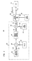
- Transmitter 100 for the i th transmitter includes a serial arrangement of: spectrum generator 110; multiplier 120; inverse Fourier transform device 130; multiplier 140; and pulse amplitude modulator 150.
- the output from multiplier 140, on lead 141, is a transmitter pulse p i ( t ) .
- the output from stream generator and pulse amplitude modulator (PAM) device 150, on lead 151, is the transmitted time signal produced by modulating delayed versions of the transmitter pulse with data symbols provided by data source 180. Accordingly, device 150 effects generation of a stream of delayed versions of p i ( t ).
- the transmitted time signal on lead 151 serves as the input to channel 50; channel 50 has a frequency domain characteristic designated H ( f ). Equation (3) is the ST-CDMA equivalent to equation (1) for SS-CDMA.
- spectrum generator 110 produces a frequency characteristic, designated S ( f ), on lead 111.
- S ( f ) a frequency characteristic
- Multiplier 120 has as its second input, on lead 122, a signal designated PN i ( f ) , that is, a frequency domain pseudo-noise function.
- Multiplier 140 has as its second input, on lead 142, a signal designated w ( t ), that is, a time domain window signal.
- PN i ( f ) is a complex frequency function which has modulus one
- w ( t ) 1 over a time interval of interest
- 2 the square of the magnitude of the frequency domain characteristic emitted from multiplier 140
- the square of the magnitude of the frequency domain characteristic of any time domain signal is generally referred to as the spectrum or the spectral density. Accordingly, by way of terminology, the arrangement of elements 110-140, 160, and 170 is called the transmitter spectral encoder 101, that is, this spectral encoder 101 generates the transmitter pulse p i ( t ) .
- the code assigned to source 160 which modulates S ( f ), can be a complex-valued PN-sequence, generally of the form where q ( f ) is a short pulse in the frequency domain of width f c . There are a total of M pulses, and the bandwidth of PN i ( f ) is Mf c .
- q ( f ) can be a rectangular pulse (as will be employed to generate FIG. 2); however, other pulse shapes for q ( f ) can be used to better confine the energy of the transmitter pulse to the symbol intervals.
- each sequence element can be chosen from a set of uniformly spaced points on the unit circle in the complex plane.
- demodulation by the "conjugate" code in which each PN-sequence element is replaced by its conjugate, enables detection of the transmitted data sequence. If, however, the decoder is matched to a different PN-sequence, then the output signal from the given receiver is additive low-intensity interference. Details of decoding will be presented shortly.
- FIG. 2 An example of a ST-CDMA transmitter pulse obtained from a S ( f ) which is constant over the normalized frequency interval [-1/2, 1/2] is shown in FIG. 2.
- the random sequence used to modulate the spectrum has length 256. Only 128 sequence elements are chosen randomly, however, since this random sequence and its conjugate modulate the positive and negative halves of S ( f ), respectively. This guarantees that p i ( t ) is real-valued.
- p ( t ) is of infinite duration, and therefore in a practical implementation must be truncated in time by a time window such as device 170 of FIG. 1.
- the signal appearing on lead 131 which corresponds to p ( t ) of infinite duration, is designated the intermediate time signal.
- the inverse Fourier transform operation performed by device 130 in spectral encoder 101 may be implemented in a straightforward manner by conventional surface acoustic wave (SAW) chirp filters.
- SAW surface acoustic wave
- a second embodiment to implement transmitter 100 is to precompute p i ( t ), as guided by the circuitry and concomitant operations depicted by spectral encoder 101 of FIG. 1, and then synthesize filter 330 of FIG. 3 having p i ( t ) as the impulse response.
- the transmitted time signal on lead 331, is then the output of this filter in response to a series of short pulses produced at the rate 1/ T by short pulse generator 310, as modulated in modulator 320 by data symbols produced by data source 180.
- These short pulses (which ideally are a series of delta functions) are "spread" in time by such a spectral encoder (hence the origin of the name "spread-time CDMA").
- ST-CDMA receiver 400 or "spectral" decoder, shown in FIG. 4 includes the serial combination of: receiver multiplier 410; Fourier transformer 420; conjugate modulator 430; and detector 440.
- the incoming channel signal to be processed is received from channel 50 over lead 51.
- the incoming channel signal is multiplied, via multiplier 410, by a receiver time window signal w R ( t ) provided by device 450, and then delivered to signal separator 415.
- the incoming channel signal is partitioned by the combination of multiplier 410, window 450, and separator 415 into a sequence of time signals wherein each partitioned time signal is of duration T ', where T ' ⁇ T .
- T ' is the duration of the transmitter pulse.
- Synchronization for this partitioning is received by window 450 from detector 440 over lead 451.
- Each partitioned time signal is delivered to Fourier transform device 420 from separator 415 via lead 411.
- Each of these partitioned time signals is converted, one at a time, to a frequency domain representation by Fourier transformer 420 to produce a frequency domain representation -- designated the received characteristic -- for each partitioned time signal.
- each time signal only has values in an interval of duration T ' and is zero elsewhere.
- the received frequency characteristic on lead 421 in response to each transmitted pulse b ( i ) / k p i ( t ) is b ( i ) / k S ( f ) H ( f ) PN i ( f ) (ignoring the effect of w R ( t ).
- the received characteristic is multiplied in multiplier 430 by: frequency characteristic S ( f ); the conjugate of the pseudo-noise source PN i ( f ) , i.e., PN i * ( f ); and the conjugate to the channel characteristic H ( f ) , i.e., H *( f ).
- the frequency characteristic on lead 431 is b ( i ) / k
- Integrator 441 then integrates the characteristic on lead 431 over the bandwidth for which S ( f ) > 0. Since
- 2 ⁇ 0 for all frequencies, sampler 445 decides if b and ( i ) / k 1(-1) whenever the integration is positive (negative). Synchronization of a transmitter-receiver pair is accomplished via element 443 in any conventional, well-known manner. The synchronization signal is provided to integrator 441, sampler 445, receiver time window 450, separator 415 and Fourier transformer 420.
- Fourier transformer 420 may also be implemented with a surface acoustic wave device as set forth in the aforementioned article by Milstein and Das.
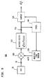
- filter 510 has a frequency domain characteristic given by the product of: (a) the conjugate of the Fourier transform of the transmitter pulse, that is, p and i *( f ) where p and i ( f ) is the Fourier transform of p i ( t ); and (b) H *( f ) S ( f ).
- the output of filter 510, appearing on lead 511, is sampled by sampler 520 to produce the estimates ⁇ b and ( i ) / k ⁇ .
- Multiplier 505, receiver time window 530, and synchronization device 540 are counterparts to elements 410, 450 and 443 in FIG. 4.
- the SIR -- the ratio of received signal power to received interference power at the output of integrator 441 of FIG. 4 -- is a functional of the square of the magnitude of the transmitter characteristic, that is, the spectrum of the transmitter pulse.
- the spectrum that maximizes the SIR subject to an average transmitted power constraint can be determined. It is required to subject to where is is is assumed that
- 0 for
- H ( f ) is composed of two ideal bandpass channels each having bandwidth W with respective support on disconnected or separate frequency bands. Since H ( f ) is even, the total available channel bandwidth is 4 W .
- the transmitter pulse can be matched to this channel, which results in essentially the same performance as for the case of an ideal bandlimited channel with bandwidth 4W.
- This SIR [4wT/(k-1)] 1 ⁇ 2 in the absence to background noise.
Landscapes
- Engineering & Computer Science (AREA)
- Signal Processing (AREA)
- Computer Networks & Wireless Communication (AREA)
- Mobile Radio Communication Systems (AREA)
- Noise Elimination (AREA)
- Compression, Expansion, Code Conversion, And Decoders (AREA)
- Transmitters (AREA)
Claims (7)
- Schaltungsanordnung in einem Sender (100) zum spektralen Codieren eines Senderpulses zur Übermittlung über einen Kanal (50) zu einem Empfänger, wobei der Kanal eine gegebene Frequenzdomänen-Charakteristik und Rauschstörung hat, wobei die Schaltungsanordnung (101) aufweisteine Einrichtung (110) zum Erzeugen eines Frequenzdomänen-Senderpulses mit einem Senderfrequenzbetrag, wobei der Frequenzbetrag durch Bezugnahme auf die Frequenzdomänen-Charakteristik des Kanals bestimmt ist, um ein Signal-Rauschverhältnis beim Empfänger für eine Leistungsbeschränkung auf dem Senderpuls zu maximieren,eine Einrichtung (120) zum Modulieren des Senderfrequenzbetrags mit einer komplexen Frequenzfunktion mit einem Einheitsmodul und einer durch eine Pseudo-Rauschsequenz bestimmten Phasenfunktion, um eine codierte modulierte Charakteristik zu erzeugen, undeiner Einrichtung (130) zum inversen Fourier-Transformieren der codierten modulierten Charakteristik, um ein dem Senderpuls entsprechendes transformiertes Zeitsignal zu liefern.
- Schaltungsanordnung nach Anspruch 1, ferner mit einer Einrichtung (170) zum Abschneiden des transformierten Zeitsignals in der Zeitdomäne, wodurch der gesendete Puls erzeugt wird.
- Sender (100) nach Anspruch 2, ferner mit einer Quelle (180) von mit einer Symbolrate erzeugten Datensymbolen und worin der Sender ferner aufweisteine Einrichtung (150) zum Regenerieren des Senderpulses mit der Symbolrate, um einen Strom von Senderpulsen zu erzeugen, undeine Einrichtung zum Modulieren des Stroms von Senderpulsen mit den Datensymbolen, um ein gesendetes Zeitsignal (151) zu erzeugen, das als eine Eingabe in den Kanal (50) dient.
- Schaltungsanordnung nach Anspruch 3, worin die Einrichtung zum inversen Fourier-Transformieren eine Vorrichtung für akustische Oberflächenwellen enthält.
- Verfahren zum Erzeugen eines spektral codierten Senderpulses in einem Sender zur Ausbreitung über einen Kanal zu einem Empfänger, wobei der Kanal eine gegebene Frequenzdomänen-Charakteristik und Rauschstörung hat, wobei das Verfahren die Schritte aufweist:Erzeugen eines Frequenzdomänen-Senderpulses mit einem Senderfrequenzbetrag, wobei der Frequenzbetrag durch Bezugnahme auf die Frequenzdomänen-Charakteristik des Kanals bestimmt ist, um ein Signal-Rauschverhältnis beim Empfänger für eine Leistungsbeschränkung auf dem Senderpuls zu maximieren,Modulieren des Senderfrequenzbetrags mit einer komplexen Frequenzfunktion mit einem Einheitsmodul und einer durch eine Pseudo-Rauschsequenz bestimmten Phasenfunktion, um eine codierte modulierte Charakteristik zu erzeugen, undTransformieren der codierten modulierten Charakteristik, um ein dem Senderpuls entsprechendes transformiertes Signal zu erzeugen.
- Verfahren nach Anspruch 5, ferner mit dem Schritt eines Abschneidens des transformierten Signals, um den Senderpuls zu erzeugen.
- Verfahren nach Anspruch 6, worin der Sender eine Quelle von mit einer Symbolrate erzeugten Datensymbolen enthält und das Verfahren ferner die Schritte aufweist:Regenerieren des Senderpulses mit der Symbolrate, um einen Strom von Senderpulsen zu erzeugen, undModulieren des Stroms Senderpulse mit den Datensymbolen, um ein als eine Eingabe in den Kanal dienendes gesendetes Zeitsignal zu erzeugen.
Applications Claiming Priority (3)
| Application Number | Priority Date | Filing Date | Title |
|---|---|---|---|
| US796642 | 1991-11-22 | ||
| US07/796,642 US5175743A (en) | 1991-11-22 | 1991-11-22 | Spread-time code division multiple access technique with arbitrary spectral shaping |
| PCT/US1992/009079 WO1993010604A1 (en) | 1991-11-22 | 1992-10-21 | A spread-time code division multiple access technique with arbitrary spectral shaping |
Publications (3)
| Publication Number | Publication Date |
|---|---|
| EP0613599A1 EP0613599A1 (de) | 1994-09-07 |
| EP0613599A4 EP0613599A4 (en) | 1996-06-26 |
| EP0613599B1 true EP0613599B1 (de) | 1999-05-26 |
Family
ID=25168680
Family Applications (1)
| Application Number | Title | Priority Date | Filing Date |
|---|---|---|---|
| EP92924125A Expired - Lifetime EP0613599B1 (de) | 1991-11-22 | 1992-10-21 | Zeitspreiz-kodemultiplexvielfachzugriffsverfahren mit beliebiger spektrumformung |
Country Status (6)
| Country | Link |
|---|---|
| US (1) | US5175743A (de) |
| EP (1) | EP0613599B1 (de) |
| JP (1) | JP2808490B2 (de) |
| CA (1) | CA2123488C (de) |
| DE (1) | DE69229277T2 (de) |
| WO (1) | WO1993010604A1 (de) |
Families Citing this family (14)
| Publication number | Priority date | Publication date | Assignee | Title |
|---|---|---|---|---|
| US5353302A (en) * | 1993-02-03 | 1994-10-04 | At&T Bell Laboratories | Signal despreader for CDMA systems |
| US5345470A (en) * | 1993-03-31 | 1994-09-06 | Alexander Richard O | Methods of minimizing the interference between many multiple FMCW radars |
| US5640385A (en) * | 1994-01-04 | 1997-06-17 | Motorola, Inc. | Method and apparatus for simultaneous wideband and narrowband wireless communication |
| FI96154C (fi) * | 1994-05-30 | 1996-05-10 | Nokia Telecommunications Oy | Menetelmä tilaajapäätelaitteiden synkronisoimiseksi, tukiasema sekä tilaajapäätelaite |
| US5519837A (en) * | 1994-07-29 | 1996-05-21 | International Business Machines Corporation | Pseudo-round-robin arbitration for a shared resource system providing fairness and high throughput |
| US5677927A (en) * | 1994-09-20 | 1997-10-14 | Pulson Communications Corporation | Ultrawide-band communication system and method |
| FI97505C (fi) * | 1994-11-29 | 1996-12-27 | Nokia Telecommunications Oy | Tiedonsiirtomenetelmä, lähetin ja vastaanotin |
| US5623485A (en) * | 1995-02-21 | 1997-04-22 | Lucent Technologies Inc. | Dual mode code division multiple access communication system and method |
| DE19735097A1 (de) * | 1997-08-13 | 1999-02-18 | Deutsche Telekom Ag | Verfahren und Schaltungsanordnung zur Übertragung von Nachrichten |
| US6363049B1 (en) * | 1998-03-25 | 2002-03-26 | Sony Corporation | Adaptive acquisition system for CDMA and spread spectrum systems compensating for frequency offset and noise |
| KR100383860B1 (ko) * | 2000-11-23 | 2003-05-14 | 주식회사 카서 | 극성교번 펄스폭 코드 분할 다중 접속 방식 및 이를이용한 통화 장비간의 거리 측정 방법 |
| WO2003036840A1 (en) * | 2001-10-19 | 2003-05-01 | Matsushita Electric Industrial Co., Ltd. | System and method for spread spectrum communication |
| CN110426679B (zh) * | 2019-07-20 | 2022-05-24 | 中国船舶重工集团公司第七二四研究所 | 相位编码信号信干比提高的方法 |
| CN113504030B (zh) * | 2021-07-20 | 2024-03-12 | 安徽问天量子科技股份有限公司 | 高速脉冲激光器相位随机化测试装置及方法 |
Family Cites Families (8)
| Publication number | Priority date | Publication date | Assignee | Title |
|---|---|---|---|---|
| US4313197A (en) * | 1980-04-09 | 1982-01-26 | Bell Telephone Laboratories, Incorporated | Spread spectrum arrangement for (de)multiplexing speech signals and nonspeech signals |
| US4779266A (en) * | 1986-03-10 | 1988-10-18 | Bell Communications Research, Inc. | Encoding and decoding for code division multiple access communication systems |
| JPS6393233A (ja) * | 1986-10-08 | 1988-04-23 | Oki Electric Ind Co Ltd | スペクトル拡散通信システム |
| US4922506A (en) * | 1988-01-11 | 1990-05-01 | Sicom Corporation | Compensating for distortion in a communication channel |
| US5134630A (en) * | 1989-04-12 | 1992-07-28 | National Research Development Corporation | Method and apparatus for transparent tone-in-band transmitter, receiver and system processing |
| US5068874A (en) * | 1989-08-07 | 1991-11-26 | Motorola, Inc. | Spectrally efficient digital fm modulation system |
| US5018088A (en) * | 1989-10-02 | 1991-05-21 | The Johns Hopkins University | Adaptive locally-optimum detection signal processor and processing methods |
| US5029184A (en) * | 1990-01-24 | 1991-07-02 | Harris Corporation | Low probability of intercept communication system |
-
1991
- 1991-11-22 US US07/796,642 patent/US5175743A/en not_active Expired - Lifetime
-
1992
- 1992-10-21 CA CA002123488A patent/CA2123488C/en not_active Expired - Fee Related
- 1992-10-21 JP JP5509257A patent/JP2808490B2/ja not_active Expired - Lifetime
- 1992-10-21 DE DE69229277T patent/DE69229277T2/de not_active Expired - Fee Related
- 1992-10-21 WO PCT/US1992/009079 patent/WO1993010604A1/en not_active Ceased
- 1992-10-21 EP EP92924125A patent/EP0613599B1/de not_active Expired - Lifetime
Also Published As
| Publication number | Publication date |
|---|---|
| EP0613599A4 (en) | 1996-06-26 |
| US5175743A (en) | 1992-12-29 |
| JPH07501192A (ja) | 1995-02-02 |
| JP2808490B2 (ja) | 1998-10-08 |
| DE69229277D1 (de) | 1999-07-01 |
| CA2123488A1 (en) | 1993-05-27 |
| CA2123488C (en) | 1999-01-05 |
| WO1993010604A1 (en) | 1993-05-27 |
| DE69229277T2 (de) | 1999-12-30 |
| EP0613599A1 (de) | 1994-09-07 |
Similar Documents
| Publication | Publication Date | Title |
|---|---|---|
| US5177768A (en) | Spread-time code division multiple access technique with arbitrary spectral shaping | |
| EP0613599B1 (de) | Zeitspreiz-kodemultiplexvielfachzugriffsverfahren mit beliebiger spektrumformung | |
| US6496104B2 (en) | System and method for communication via power lines using ultra-short pulses | |
| Fathallah et al. | Passive optical fast frequency-hop CDMA communications system | |
| US5563906A (en) | Method of geometric harmonic modulation (GHM) | |
| US5760941A (en) | System and method for performing optical code division multiple access communication using bipolar codes | |
| US6850733B2 (en) | Method for conveying application data with carrierless ultra wideband wireless signals | |
| DE69609158D1 (de) | Verfahren und gerät zur verwendung der gesamten spektralen sendeleistung in einem spreizspektrumübertragungssystem zur energie- und phasenzeitnachführung einzelner empfänger | |
| US20030165184A1 (en) | M-ary orthogonal coded communications method and system | |
| DK1311095T3 (da) | Fremgangsmåde til digital spread-spektrum kommunikation ved Golay komplementær sekvensmodulation | |
| US5173923A (en) | Spread-time code division multiple access technique with arbitrary spectral shaping | |
| EP1302001A2 (de) | Trägerlose drahtlose ultrabreitbandsignale zum übermitteln von anwendungsdaten | |
| US5519725A (en) | Geometric harmonic modulation (GHM) for combined analog/digital transmissions | |
| US7317748B2 (en) | Methods and apparatus for transmitting and receiving randomly inverted wideband signals | |
| CN105594133B (zh) | 生成用于表示数据的信号以及确定要表示的数据的方法和装置 | |
| US5175744A (en) | Spread-time code division multiple access technique with arbitrary spectral shaping | |
| US7756424B2 (en) | Optical CDMA communications system using OTDL device | |
| US5568507A (en) | Geometric harmonic modulation (GHM) - analog implementation | |
| US8102955B2 (en) | Multi-pulse frequency shifted (MPFS) multiple access modulation for ultra wideband | |
| JP3621644B2 (ja) | スペクトル拡散多元接続符号化方式 | |
| US8275017B2 (en) | Method of packet transmission and reception of quadrature amplitude modulated signals in a frequency hopping radio system | |
| Benedetto et al. | Analysis of an optical code division multiple access scheme employing Gold sequences | |
| Parthiban et al. | Wavelet-based multiple access technique for mobile communications | |
| RU2713384C1 (ru) | Способ передачи информации с помощью широкополосных сигналов | |
| US20050058210A1 (en) | Bipolar waveform modulation for ultra wideband (UWB) communication networks |
Legal Events
| Date | Code | Title | Description |
|---|---|---|---|
| PUAI | Public reference made under article 153(3) epc to a published international application that has entered the european phase |
Free format text: ORIGINAL CODE: 0009012 |
|
| 17P | Request for examination filed |
Effective date: 19940603 |
|
| AK | Designated contracting states |
Kind code of ref document: A1 Designated state(s): DE FR GB |
|
| A4 | Supplementary search report drawn up and despatched |
Effective date: 19960508 |
|
| AK | Designated contracting states |
Kind code of ref document: A4 Designated state(s): DE FR GB |
|
| 17Q | First examination report despatched |
Effective date: 19961025 |
|
| GRAG | Despatch of communication of intention to grant |
Free format text: ORIGINAL CODE: EPIDOS AGRA |
|
| GRAG | Despatch of communication of intention to grant |
Free format text: ORIGINAL CODE: EPIDOS AGRA |
|
| GRAH | Despatch of communication of intention to grant a patent |
Free format text: ORIGINAL CODE: EPIDOS IGRA |
|
| GRAH | Despatch of communication of intention to grant a patent |
Free format text: ORIGINAL CODE: EPIDOS IGRA |
|
| GRAA | (expected) grant |
Free format text: ORIGINAL CODE: 0009210 |
|
| AK | Designated contracting states |
Kind code of ref document: B1 Designated state(s): DE FR GB |
|
| REF | Corresponds to: |
Ref document number: 69229277 Country of ref document: DE Date of ref document: 19990701 |
|
| ET | Fr: translation filed | ||
| PLBE | No opposition filed within time limit |
Free format text: ORIGINAL CODE: 0009261 |
|
| STAA | Information on the status of an ep patent application or granted ep patent |
Free format text: STATUS: NO OPPOSITION FILED WITHIN TIME LIMIT |
|
| 26N | No opposition filed | ||
| PGFP | Annual fee paid to national office [announced via postgrant information from national office to epo] |
Ref country code: FR Payment date: 20001002 Year of fee payment: 9 |
|
| PGFP | Annual fee paid to national office [announced via postgrant information from national office to epo] |
Ref country code: DE Payment date: 20001003 Year of fee payment: 9 |
|
| PGFP | Annual fee paid to national office [announced via postgrant information from national office to epo] |
Ref country code: GB Payment date: 20001004 Year of fee payment: 9 |
|
| PG25 | Lapsed in a contracting state [announced via postgrant information from national office to epo] |
Ref country code: GB Free format text: LAPSE BECAUSE OF NON-PAYMENT OF DUE FEES Effective date: 20011021 |
|
| REG | Reference to a national code |
Ref country code: GB Ref legal event code: IF02 |
|
| GBPC | Gb: european patent ceased through non-payment of renewal fee |
Effective date: 20011021 |
|
| PG25 | Lapsed in a contracting state [announced via postgrant information from national office to epo] |
Ref country code: FR Free format text: LAPSE BECAUSE OF NON-PAYMENT OF DUE FEES Effective date: 20020628 |
|
| PG25 | Lapsed in a contracting state [announced via postgrant information from national office to epo] |
Ref country code: DE Free format text: LAPSE BECAUSE OF NON-PAYMENT OF DUE FEES Effective date: 20020702 |
|
| REG | Reference to a national code |
Ref country code: FR Ref legal event code: ST |