EP0613202A2 - Verfahren zur Reaktivierung von verschlossenen Batterien mit flüssigem Elektrolyt - Google Patents
Verfahren zur Reaktivierung von verschlossenen Batterien mit flüssigem Elektrolyt Download PDFInfo
- Publication number
- EP0613202A2 EP0613202A2 EP93310006A EP93310006A EP0613202A2 EP 0613202 A2 EP0613202 A2 EP 0613202A2 EP 93310006 A EP93310006 A EP 93310006A EP 93310006 A EP93310006 A EP 93310006A EP 0613202 A2 EP0613202 A2 EP 0613202A2
- Authority
- EP
- European Patent Office
- Prior art keywords
- cell
- battery
- electrolyte
- batteries
- opening
- Prior art date
- Legal status (The legal status is an assumption and is not a legal conclusion. Google has not performed a legal analysis and makes no representation as to the accuracy of the status listed.)
- Withdrawn
Links
- 238000000034 method Methods 0.000 title claims abstract description 42
- 230000008569 process Effects 0.000 title description 19
- 239000011244 liquid electrolyte Substances 0.000 title description 7
- 239000003792 electrolyte Substances 0.000 claims abstract description 41
- 238000005553 drilling Methods 0.000 claims abstract description 7
- 238000007789 sealing Methods 0.000 claims abstract description 6
- 239000007789 gas Substances 0.000 claims description 11
- 229910000679 solder Inorganic materials 0.000 claims description 3
- 239000000463 material Substances 0.000 abstract description 11
- 238000010521 absorption reaction Methods 0.000 abstract description 6
- 239000007788 liquid Substances 0.000 abstract description 4
- 210000004027 cell Anatomy 0.000 description 102
- KWYUFKZDYYNOTN-UHFFFAOYSA-M Potassium hydroxide Chemical compound [OH-].[K+] KWYUFKZDYYNOTN-UHFFFAOYSA-M 0.000 description 22
- 230000007246 mechanism Effects 0.000 description 7
- PXHVJJICTQNCMI-UHFFFAOYSA-N Nickel Chemical compound [Ni] PXHVJJICTQNCMI-UHFFFAOYSA-N 0.000 description 4
- 238000001035 drying Methods 0.000 description 4
- XLYOFNOQVPJJNP-UHFFFAOYSA-N water Substances O XLYOFNOQVPJJNP-UHFFFAOYSA-N 0.000 description 4
- 230000035508 accumulation Effects 0.000 description 3
- 238000009825 accumulation Methods 0.000 description 3
- 229910052793 cadmium Inorganic materials 0.000 description 3
- BDOSMKKIYDKNTQ-UHFFFAOYSA-N cadmium atom Chemical compound [Cd] BDOSMKKIYDKNTQ-UHFFFAOYSA-N 0.000 description 3
- 238000007599 discharging Methods 0.000 description 3
- 238000002347 injection Methods 0.000 description 3
- 239000007924 injection Substances 0.000 description 3
- 239000011148 porous material Substances 0.000 description 3
- IJGRMHOSHXDMSA-UHFFFAOYSA-N Atomic nitrogen Chemical compound N#N IJGRMHOSHXDMSA-UHFFFAOYSA-N 0.000 description 2
- 230000009471 action Effects 0.000 description 2
- 238000013459 approach Methods 0.000 description 2
- QVGXLLKOCUKJST-UHFFFAOYSA-N atomic oxygen Chemical compound [O] QVGXLLKOCUKJST-UHFFFAOYSA-N 0.000 description 2
- 230000008901 benefit Effects 0.000 description 2
- UDRRLPGVCZOTQW-UHFFFAOYSA-N bismuth lead Chemical compound [Pb].[Bi] UDRRLPGVCZOTQW-UHFFFAOYSA-N 0.000 description 2
- OJIJEKBXJYRIBZ-UHFFFAOYSA-N cadmium nickel Chemical compound [Ni].[Cd] OJIJEKBXJYRIBZ-UHFFFAOYSA-N 0.000 description 2
- 210000002421 cell wall Anatomy 0.000 description 2
- 239000002001 electrolyte material Substances 0.000 description 2
- 238000002474 experimental method Methods 0.000 description 2
- 239000002920 hazardous waste Substances 0.000 description 2
- 239000011810 insulating material Substances 0.000 description 2
- 150000002500 ions Chemical class 0.000 description 2
- 238000003754 machining Methods 0.000 description 2
- 229910052759 nickel Inorganic materials 0.000 description 2
- 239000001301 oxygen Substances 0.000 description 2
- 229910052760 oxygen Inorganic materials 0.000 description 2
- 238000011084 recovery Methods 0.000 description 2
- 239000000243 solution Substances 0.000 description 2
- 238000012546 transfer Methods 0.000 description 2
- UFHFLCQGNIYNRP-UHFFFAOYSA-N Hydrogen Chemical compound [H][H] UFHFLCQGNIYNRP-UHFFFAOYSA-N 0.000 description 1
- 229910000831 Steel Inorganic materials 0.000 description 1
- 230000015556 catabolic process Effects 0.000 description 1
- 230000001413 cellular effect Effects 0.000 description 1
- 239000004020 conductor Substances 0.000 description 1
- 238000010276 construction Methods 0.000 description 1
- 230000001351 cycling effect Effects 0.000 description 1
- 230000007423 decrease Effects 0.000 description 1
- 238000009826 distribution Methods 0.000 description 1
- 230000009977 dual effect Effects 0.000 description 1
- 230000005518 electrochemistry Effects 0.000 description 1
- 239000008151 electrolyte solution Substances 0.000 description 1
- 238000004146 energy storage Methods 0.000 description 1
- 238000004880 explosion Methods 0.000 description 1
- 238000010438 heat treatment Methods 0.000 description 1
- 239000001257 hydrogen Substances 0.000 description 1
- 229910052739 hydrogen Inorganic materials 0.000 description 1
- 230000001771 impaired effect Effects 0.000 description 1
- 238000007689 inspection Methods 0.000 description 1
- 239000012212 insulator Substances 0.000 description 1
- 238000003698 laser cutting Methods 0.000 description 1
- 239000006193 liquid solution Substances 0.000 description 1
- 238000004519 manufacturing process Methods 0.000 description 1
- 238000002844 melting Methods 0.000 description 1
- 230000008018 melting Effects 0.000 description 1
- 229910052987 metal hydride Inorganic materials 0.000 description 1
- 230000005012 migration Effects 0.000 description 1
- 238000013508 migration Methods 0.000 description 1
- 229910052757 nitrogen Inorganic materials 0.000 description 1
- 239000007774 positive electrode material Substances 0.000 description 1
- 230000009467 reduction Effects 0.000 description 1
- 230000002441 reversible effect Effects 0.000 description 1
- 238000004904 shortening Methods 0.000 description 1
- 238000005476 soldering Methods 0.000 description 1
- 239000010959 steel Substances 0.000 description 1
- 239000000126 substance Substances 0.000 description 1
- 238000013022 venting Methods 0.000 description 1
- 239000011800 void material Substances 0.000 description 1
- 239000002699 waste material Substances 0.000 description 1
- 238000009736 wetting Methods 0.000 description 1
Images

Classifications
-
- H—ELECTRICITY
- H01—ELECTRIC ELEMENTS
- H01M—PROCESSES OR MEANS, e.g. BATTERIES, FOR THE DIRECT CONVERSION OF CHEMICAL ENERGY INTO ELECTRICAL ENERGY
- H01M10/00—Secondary cells; Manufacture thereof
- H01M10/42—Methods or arrangements for servicing or maintenance of secondary cells or secondary half-cells
- H01M10/4242—Regeneration of electrolyte or reactants
-
- Y—GENERAL TAGGING OF NEW TECHNOLOGICAL DEVELOPMENTS; GENERAL TAGGING OF CROSS-SECTIONAL TECHNOLOGIES SPANNING OVER SEVERAL SECTIONS OF THE IPC; TECHNICAL SUBJECTS COVERED BY FORMER USPC CROSS-REFERENCE ART COLLECTIONS [XRACs] AND DIGESTS
- Y02—TECHNOLOGIES OR APPLICATIONS FOR MITIGATION OR ADAPTATION AGAINST CLIMATE CHANGE
- Y02E—REDUCTION OF GREENHOUSE GAS [GHG] EMISSIONS, RELATED TO ENERGY GENERATION, TRANSMISSION OR DISTRIBUTION
- Y02E60/00—Enabling technologies; Technologies with a potential or indirect contribution to GHG emissions mitigation
- Y02E60/10—Energy storage using batteries
Definitions
- the present invention relates to a process for recovering the recharge life cycle of sealed liquid electrolyte batteries.
- the invention relates to a method for recovering nickel-cadmium (Ni-Cd) cells which have degraded to the point where they no longer accept or are capable of holding a voltage charge.
- Ni-Cd nickel-cadmium
- the preferred embodiment of the invention is directed to Ni-Cd batteries, but the principles of the invention are equally applicable to other sealed liquid electrolyte rechargeable batteries, such as nickel-metal-hydride, or rechargeable alkaline batteries.
- All batteries contain an electrolyte of one form or another.
- the purpose is to provide a medium in which ions move freely from one electrode to another, thereby allowing current flow.
- Both the volume and strength of the electrolyte are important to the proper operation of the battery. As long as the electrolyte parameters stay within fairly wide limits, operation is not impaired, but if either the volume or strength of the electrolyte move outside of these fairly wide limits, the battery operation degrades.
- this electrolyte takes the form of a liquid solution of potassium hydroxide (KOH) which is soaked into the insulating material and in contact with the battery electrodes.
- KOH potassium hydroxide
- the invention is primarily concerned with rechargeable batteries of the general type which may be discharged at peak current drains up to 10-20 amps (A) but typically operate between 0.05 and 10 ampere hour (Ah) capacities.
- the charging of such batteries is typically accomplished at a charge rate of 0.1-1 amps.
- the charge and discharge rate of batteries is frequently referred to as the "C-rate,” which is defined as the current flow out of or into a cell numerically equal to the cells rated capacity.
- the C-rate of a 1-Ah cell is 1 A
- the C-rate of a 2.5-Ah cell is 2.5 A.
- the C-rate concept is useful to enable a comparison of different size cells on the basis of a scaling of charge and discharge rates, for different cells behave similarly in terms of their voltage and operation time when they are charged or discharged at the same C-rate.
- the Ni-Cd batteries can operate with discharge rates up to 20 C, and are typically recharged at rates of 0.02 C - 0.3 C.
- a Ni-Cd battery is typically constructed of a tightly wrapped coil of materials consisting of a cadmium plate, a nickel plate and a porous insulating material separating the plates, which material is impregnated with an electrolyte solution such as KOH.
- the electrochemistry of a Ni-Cd cell determines its nominal operating voltage; for a Ni-Cd battery this nominal operating voltage is 1.2 volts.
- the cell chemistry causes the nominal voltage to "droop" during discharge, although the discharge voltage characteristics are quite flat over an extended operating time, and the "droop" becomes sudden and quite drastic after a predetermined operating time interval.
- Ni-Cd battery After a Ni-Cd battery has been recharged, the voltage operating characteristic returns to its initial 1.2 volt nominal voltage, and the voltage operating curve is repeatable over many subsequent charge and recharge cycles.
- Commercially available Ni-Cd batteries are typically advertised to have an operating life of 300-500 recharge cycles.
- the continued charging and discharging of the battery, and the heat and high internal pressures associated therewith results in a buildup of gases along the interface between the battery plates and the separator material and into the surface of the battery plates, and this gaseous buildup reduces the efficiency of transfer of ions between the plates and the electrolyte-filled separator material.
- the gaseous buildup may not necessarily be of sufficiently high pressure so as to release the internal battery pressure valve mechanism, but the accumulation may be sufficient to reduce the charging/discharging efficiency of the battery over time. As a gaseous buildup accumulates over time, the overall battery efficiency may degrade to the point where the battery is deemed to be no longer capable of accepting the charge, and is therefore discarded.
- the battery recharge cycle is a particularly important factor in battery life, as the battery recharge current may cause a buildup of internal heat in the battery.
- Minimum commercial battery recharge rates are about C/20, i.e., requiring 20 hours to recharge a battery to its rated capacity. However, since the battery charging efficiency is under 100 percent, it is more typical to require 36-48 hours for recharging a battery to its rated capacity. Recharging efficiency decreases as the battery nears its full recharge. As the battery is recharged to within its final few percentage points of full capacity, the cell approaches an overcharge condition, and in this condition the cell generates gaseous oxygen 02. If the recharge current rate is low, a continuous overcharge does not damage the battery since the cell can electrochemically recombine the total oxygen volume.
- a commercially-available Ni-Cd battery pack typically is an assembly of a multiplicity of Ni-Cd cells, usually connected electrically in series. This provides a predetermined battery-pack output voltage which is determined by the number of series-connected cells, and the battery capacity is determined by the respective sizes of each of the cells. However, cells of the same size and manufacture do exhibit actual capacities that differ, up to ⁇ 10%, from a mean value. When such cells are connected into a multi-cell capacity, these variations can cause some cells to give up the last of their usable capacity and other cells to retain a certain capacity upon discharge of the battery pack. If the extent of battery-pack discharge is deep enough, one or more cells may be brought to zero voltage, which can cause the condition known as cell reversal.
- Ni-Cd batteries can further experience actual electrolyte leakage under certain conditions, particularly conditions wherein the battery is connected into a circuit where there is a very small amount of current drain over an extended period of time.
- a small amount of electrolyte may leak from the seals of the cell in an extended time period of from one week to several months. This is known as "creep" leakage, and usually can be identified upon inspection, as a white fuzz appearing around the top seal of the cell.
- Such a battery can usually be recharged, although the condition does contribute to the overall shortening of the battery life cycle.
- Ni-Cd battery Another factor which shortens the overall life of a Ni-Cd battery is the operating environment temperature. In general, for every 10°C increase in the average temperature of operation of a Ni-Cd battery, the cell life is cut in half. This is thought to be caused by a loss of electrolyte in the cell, combined with the breakdown of the separator material which absorbs the electrolyte liquid, or an accumulation of gases which interferes with the charge/discharge process.
- the present invention comprises a method for recovering sealed liquid electrolyte batteries, particularly Ni-Cd batteries, wherein the energy storage capacity of the batteries may be restored, and the batteries may be reused through an extended operating life.
- the method involves a number of steps wherein electrolyte material is reintroduced into the cell through a small opening created in the exterior cell wall, the cell is stored for a predetermined time to permit the electrolyte to become fully absorbed into the cell, the cell is run through several charge/discharge cycles, culminating with a final charge to full voltage, and the exterior cell wall is sealed.
- a principal object and advantage of the invention is to provide a method for recovering spent batteries, to permit the batteries to be replaced in service for an extended series of charge/discharge cycles.
- the present invention is described with reference to a particular type of Ni-Cd battery cell, but the principles of the invention are readily applied to sealed liquid electrolyte batteries of various types and capacities.
- the process described herein is related to a battery pack which is typically used in connection with cellular telephone equipment, wherein six Ni-Cd cells are connected in series to create the battery pack, and the battery pack has an initial rating of 7.5 volts DC, and 1400-1500 milliamp hour capacity.
- the several steps of the invention process may be applied to other Ni-Cd cells of differing capacity, or other types of sealed electrolyte batteries, after experimental adjustment of the various parameters disclosed herein.
- FIG. 1 shows a typical liquid electrolyte battery cell in exploded view.
- An outer case 10 may be made from nickel or nickel-plated steel.
- the inner cell electrodes 20 are in the form of a tightly-wound coil, consisting of an outer layer which forms a negative plate, a separator material and an inner layer which forms a positive plate.
- An insulating seal ring 30 is seated atop the interior electrode coil, and a second insulating ring 32 is positioned in spaced-apart relation above insulating ring 30.
- a spring clip 40 has a bottom surface which contacts against the upper edges of one of the layers of the coil 20, and an upper surface which is spring biased against a vent plate 50. Vent plate 50 has a central opening 52 therethrough, which is normally closed by a vent plug 60.
- a top cover 70 rests atop vent plug 60, and top cover 70, vent plug 60 and vent plate 50 are all compressed in the flange 33 of insulator 32.
- the outer case 10 is initially formed in a cylindrical shape, and the groove 12 and top flange 11 are formed after the other components have been inserted into the cell outer case. In their assembled position, insulating flange 30 is positioned beneath groove 12, and insulating flange 32 is positioned above groove 12 and within the interior channel 13 created by flange 11.
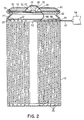
- FIG. 2 shows a typical cell of the type shown in FIG. 1 in elevation cross-section view, after all components have been properly assembled.
- FIG. 2 also shows one step of the process, wherein a hollow needle 62 is inserted through a drilled hole 14 in the sidewall of outer case 10. The hole 14 is extended through the sidewall of case 10 and also through the respective upwardly-projecting plates of the inner cell electrodes 20. Needle 62 has an open end 53 through which liquid may be ejected into the interior of the cell, and needle 62 is typically connected to a syringe 54 or other suitable liquid transfer device.
- the interior cell is constructed so that one layer 21 of the interior electrodes is displaced laterally relative to the other layer 22 of the electrodes, so that the lower edges of electrode 21 project downwardly and into contact against the inside surface of the case 10, and the upper edges of the electrodes 22 project upwardly into the upper region of the case 10.
- a metallic spring clip 40 rests atop a plurality of the upper edges of electrode 22 and makes electrical contact therewith.
- Insulating ring 30 also rests atop some of the upper edges of electrode 22, but a central opening through insulating ring 30 permits spring clip 40 to make the necessary electrical contact with the electrode edges.
- the top surface of spring clip 40 is biased against the lower surface of vent plate 50, which is also constructed of a metallic conductor.
- Top cover 70 is also metallic, and top cover 70 rests atop vent plate 50; there is, therefore, electrical conductivity between the top edges of electrodes 22 to the top cover 70, via spring clip 40 and vent plate 50. Top cover 70, therefore, becomes the positive terminal of the cell.
- Case 10 is isolated from electrical contact with any of the top conductive components by virtue of insulating ring 30 and insulating ring 32. Insulating ring 32 captures top cover 70, and vent plate 50 within its interior flange 33, and a tight seal is formed along the inner flange 33 by virtue of a machining operation which is performed at the time of construction of the cell.
- the machining operation consists of a circumferential squeezing of the outer case 10 to form the groove 12, and to flatten the upper edge of top flange 11 as shown in FIG. 2.
- the resulting seal is typically sufficiently tight so as to prevent any electrolyte from within the battery cell to escape to the outside.
- a safety valve mechanism is typically built into the cell by forming a raised opening 52 in vent plate 50.
- a rubber plug 60 is positioned in sealing relationship over this opening, and rubber plug 60 is compressed against the opening 52 by contact with the lower surface of the outer cover 70.
- Outer cover 70 typically has at least one vent hole 72 therethrough, which permits the passage of gas between the external environment of the cell and the small chamber formed between the inside walls of outer cover 70 and the outside walls of vent plate 50. If sufficient pressure develops in the interior of the cell, the rubber plug 60 may become deformed and compressed sufficiently far so as to permit the escape of pressurized gases from the cell interior to the external environment via openings 72.
- This safety valve feature is typically provided in rechargeable batteries so as to prevent possible explosions which might otherwise occur under conditions of extreme charge and/or discharge current in the cell.
- the charging and discharging of the cell inherently develops internal heat, and the amount of the heat is proportional to the magnitude of the current drain or charge which the cell experiences. Under excessive conditions this heat can build up to the point where the safety valve is released, thereby permitting the escape of electrolyte and gases from the interior of the cell to relieve the pressure.
- the process of this invention is shown in FIG. 3, and with reference to FIG. 2.
- a hole is made through the outer case 10 of the battery.
- a preferred location for this hole is shown in FIG. 2, although the hole may be made radially through the casing and the interior cell electrodes at other positions along the elevation of the battery. It is important that the hole be relatively small in diameter, and it has been found that a hole of approximately 0.020 inches (20 mils) is adequate for the purposes of the process.
- the hole is preferably made by a drilling operation, but alternatively could be made by a laser cutting technique or similar operation.
- One reason for requiring a relatively small hole at this step of the process is to facilitate the sealing of the hole at a later step in the process. It has been found that relatively high internal pressures can be built up inside the cell, approximating 150 pounds per square inch (psi), and a smaller diameter hole is relatively easier to seal in a manner which will withstand these internal operating pressures.
- the next step of the process is to inject a predetermined volume of electrolyte material into the cell through the hole drilled through the case.
- the volume of electrolyte to be injected typically represents about 30% of the capacity of the cell to hold electrolyte, and in the case of the particular Ni-Cd batteries disclosed herein this volume is approximately 0.7 cubic centimeters (cc) of electrolyte. It has been found that a KOH solution of about 21% KOH by weight is sufficient for the injected electrolyte. It has also been found that in some cases water may be injected into the cell, but the injection of water does not generally produce as satisfactory a final result as the injection of KOH.
- the injection step is accomplished by use of a surgical syringe and 16 mil needle, wherein the KOH is forcibly injected into the central region of the cell.
- a vacuum technique such as the technique of placing one or a group of cells in a vacuum chamber and immersed in KOH solution. A partial vacuum may then be drawn from the chamber, and when the vacuum is removed the cell will absorb a volume of KOH proportional to the amount of vacuum originally applied to the chamber.
- the next step of the process is to permit the injected electrolyte to become absorbed into the separator material between the electrodes in the cell. Because the electrodes in the separator material are tightly compressed in the form of a helical coil in the cell, the absorption step may require an extended period of time to assure that the electrolyte is substantially completely absorbed into the cell. In experiments which have been performed on the particular type of batteries disclosed herein, it has been found that the cells should be permitted a time period of 10-11 days for absorption to occur, and the range of time which has been found to provide some acceptable results is a time period from 6-14 days.
- the battery position it is preferable to periodically shift the battery position so that during a portion of the absorption cycle the battery may be laid on one of its sides and then flipped over to lay on its other side during the remaining portion of the cycle, or alternatively the battery may be shifted a number of times during the cycle.
- the drilled opening through the battery should not be permitted to rest vertically downward so as to cause leakage from the cell, but the opening may be horizontally directed on one side or the other.
- the next step of the process is to remove interior gases from the cell, which in the preferred embodiment is done by subjecting the cell to a number of voltage charge/discharge cycles while the opening through the cell case remains unsealed.
- three charge/discharge cycles have been found suitable for this purpose, wherein the battery is fully charged at a 600 milliamp charging rate during the charge cycle, and fully discharged at a 600 milliamp discharge rate during the charge cycles.
- One final charge is applied to the battery to place the battery in a fully charged condition.
- the hole through the outer case 10 is sealed.
- a preferred sealing technique has been found to be soldering, wherein a bismuth-lead solder has been selected for the operation.
- Bismuth-lead solder has a melting point of approximately 138°C, and therefore a relatively tight seal can be formed without subjecting the battery case to excessive temperatures.
- the process may be simultaneously applied to all of the battery cells in the pack, by subjecting each of the cells to the respective process steps disclosed herein.
- the charge/recharge cycles are simultaneously applied to all batteries in the battery pack, and at the completion of the process all of the cells are sealed according to the techniques described herein.
Landscapes
- Engineering & Computer Science (AREA)
- Manufacturing & Machinery (AREA)
- Chemical & Material Sciences (AREA)
- Chemical Kinetics & Catalysis (AREA)
- Electrochemistry (AREA)
- General Chemical & Material Sciences (AREA)
- Secondary Cells (AREA)
Applications Claiming Priority (2)
| Application Number | Priority Date | Filing Date | Title |
|---|---|---|---|
| US24151 | 1993-02-26 | ||
| US08/024,151 US5308713A (en) | 1993-02-26 | 1993-02-26 | Process for the reactivating sealed liquid electrolyte batteries |
Publications (1)
| Publication Number | Publication Date |
|---|---|
| EP0613202A2 true EP0613202A2 (de) | 1994-08-31 |
Family
ID=21819112
Family Applications (1)
| Application Number | Title | Priority Date | Filing Date |
|---|---|---|---|
| EP93310006A Withdrawn EP0613202A2 (de) | 1993-02-26 | 1993-12-10 | Verfahren zur Reaktivierung von verschlossenen Batterien mit flüssigem Elektrolyt |
Country Status (2)
| Country | Link |
|---|---|
| US (1) | US5308713A (de) |
| EP (1) | EP0613202A2 (de) |
Families Citing this family (5)
| Publication number | Priority date | Publication date | Assignee | Title |
|---|---|---|---|---|
| US5650239A (en) * | 1995-06-07 | 1997-07-22 | Zbb Technologies, Inc. | Method of electrode reconditioning |
| IT1284887B1 (it) * | 1996-10-03 | 1998-05-22 | De Nora Spa | Metodo di esclusione di una cella elementare malfunzionante di un elettrolizzatore o di un generatore elettrochimico a membrana |
| JP4354130B2 (ja) * | 2001-07-04 | 2009-10-28 | パナソニック株式会社 | 電池パックの再利用方法 |
| JP5972209B2 (ja) * | 2013-04-12 | 2016-08-17 | プライムアースEvエナジー株式会社 | 負極放電容量回復方法、及び、負極放電容量回復装置 |
| CN114497795A (zh) * | 2022-02-07 | 2022-05-13 | 沈明东 | 二次电池再生方法 |
Family Cites Families (6)
| Publication number | Priority date | Publication date | Assignee | Title |
|---|---|---|---|---|
| GB124137A (en) * | 1918-07-12 | 1919-03-20 | Kazuo Horh | Process of Resuscitating Spent Electric Dry Cells. |
| US3945846A (en) * | 1972-12-12 | 1976-03-23 | P. R. Mallory & Co. Inc. | Miniature concentric battery |
| US4182028A (en) * | 1976-08-02 | 1980-01-08 | Gte Laboratories Inc. | Hermetically sealed button-type electrochemical cell and method for making same |
| US4055709A (en) * | 1976-08-05 | 1977-10-25 | The United States Of America As Represented By The Secretary Of The Navy | Rejuvenation of nickel-cadmium battery cells |
| CA1189684A (en) * | 1982-02-16 | 1985-07-02 | Kieva Feldman | Rejuvenation of nickel-cadmium aircraft battery electrolyte |
| US4680241A (en) * | 1983-11-29 | 1987-07-14 | American Telephone And Telegraph Company, At&T Bell Laboratories | Method for restoring the lost capacity of nickel batteries and batteries formed thereby |
-
1993
- 1993-02-26 US US08/024,151 patent/US5308713A/en not_active Expired - Fee Related
- 1993-12-10 EP EP93310006A patent/EP0613202A2/de not_active Withdrawn
Also Published As
| Publication number | Publication date |
|---|---|
| US5308713A (en) | 1994-05-03 |
Similar Documents
| Publication | Publication Date | Title |
|---|---|---|
| US20100033138A1 (en) | Charging methods for nickel-zinc battery packs | |
| KR101165066B1 (ko) | 미실링 잉여부를 구비하는 파우치형 이차전지 | |
| CN104919643B (zh) | 电池的容量恢复方法、电池组的容量恢复方法、电池的容量恢复装置以及电池组的容量恢复装置 | |
| KR100467698B1 (ko) | 원통형 리튬이차전지와 이의 제조방법 | |
| WO1999063611A1 (en) | Sealed rechargeable battery plenum stabilized with state changeable substance | |
| JP3293287B2 (ja) | 角形密閉式アルカリ蓄電池とその単位電池 | |
| KR20060028180A (ko) | 리튬 이차 전지 및 그의 제조 방법 | |
| KR20180071798A (ko) | 이차 전지의 저전압 불량 검사 장치 및 방법 | |
| US20020138971A1 (en) | Method for producing a nickel metal-hydride storage battery | |
| US5308713A (en) | Process for the reactivating sealed liquid electrolyte batteries | |
| CN112018456A (zh) | 二次电池的制造方法和镍氢二次电池 | |
| KR100416096B1 (ko) | 안전변 장치와 이를 채용한 이차 전지 | |
| CN107681210B (zh) | 镍氢电池的再生方法 | |
| KR101264425B1 (ko) | 캡조립체 및 이를 이용한 이차 전지 | |
| JP7193420B2 (ja) | ニッケル水素二次電池の製造方法 | |
| CN114975896B (zh) | 镍氢蓄电池的制造方法 | |
| JPH10294125A (ja) | メンテナンスを必要としないアルカリ電解質による開放型の工業用蓄電池 | |
| KR102872634B1 (ko) | 가압 채널 및 이를 포함하는 이차전지 충방전 장치 | |
| US12237530B2 (en) | Degassing apparatus and degassing method | |
| CN112886075B (zh) | 镍氢蓄电池的制造方法 | |
| KR100782886B1 (ko) | 이차전지의 제조 방법 및 이를 위한 충전장치 | |
| KR101264461B1 (ko) | 캡조립체와 이를 이용하는 이차 전지 및 캡조립체 조립방법 | |
| KR100529067B1 (ko) | 리튬 이차전지와 그의 제조방법 | |
| JP7271488B2 (ja) | ニッケル水素蓄電池の製造方法 | |
| Barsukov | Battery selection, safety, and monitoring in mobile applications |
Legal Events
| Date | Code | Title | Description |
|---|---|---|---|
| PUAI | Public reference made under article 153(3) epc to a published international application that has entered the european phase |
Free format text: ORIGINAL CODE: 0009012 |
|
| AK | Designated contracting states |
Kind code of ref document: A2 Designated state(s): AT BE CH DE DK ES FR GB GR IE IT LI LU MC NL PT SE |
|
| RIN1 | Information on inventor provided before grant (corrected) |
Inventor name: TUOMELA, STEPHEN D. Inventor name: MAYER, WILLIAM N. |
|
| STAA | Information on the status of an ep patent application or granted ep patent |
Free format text: STATUS: THE APPLICATION HAS BEEN WITHDRAWN |
|
| 18W | Application withdrawn |
Withdrawal date: 19941125 |
|
| R18W | Application withdrawn (corrected) |
Effective date: 19941125 |