EP0612965B1 - Refrigerator with heat exchanger optimally configured - Google Patents
Refrigerator with heat exchanger optimally configured Download PDFInfo
- Publication number
- EP0612965B1 EP0612965B1 EP94102717A EP94102717A EP0612965B1 EP 0612965 B1 EP0612965 B1 EP 0612965B1 EP 94102717 A EP94102717 A EP 94102717A EP 94102717 A EP94102717 A EP 94102717A EP 0612965 B1 EP0612965 B1 EP 0612965B1
- Authority
- EP
- European Patent Office
- Prior art keywords
- refrigerator
- room
- flow
- air
- passage
- Prior art date
- Legal status (The legal status is an assumption and is not a legal conclusion. Google has not performed a legal analysis and makes no representation as to the accuracy of the status listed.)
- Expired - Lifetime
Links
- 238000007710 freezing Methods 0.000 claims description 21
- 230000008014 freezing Effects 0.000 claims description 21
- 238000005192 partition Methods 0.000 claims description 4
- 235000013311 vegetables Nutrition 0.000 description 9
- 230000003247 decreasing effect Effects 0.000 description 8
- 238000010586 diagram Methods 0.000 description 8
- 238000007664 blowing Methods 0.000 description 6
- 238000001816 cooling Methods 0.000 description 6
- 235000013305 food Nutrition 0.000 description 6
- 238000010276 construction Methods 0.000 description 5
- 238000007599 discharging Methods 0.000 description 5
- 239000003507 refrigerant Substances 0.000 description 4
- 241001274961 Rubus repens Species 0.000 description 2
- 230000004913 activation Effects 0.000 description 2
- 238000001704 evaporation Methods 0.000 description 2
- 230000008020 evaporation Effects 0.000 description 2
- 238000009499 grossing Methods 0.000 description 2
- 239000006185 dispersion Substances 0.000 description 1
- 238000001035 drying Methods 0.000 description 1
- 230000000694 effects Effects 0.000 description 1
- 230000005484 gravity Effects 0.000 description 1
- 239000007788 liquid Substances 0.000 description 1
- 239000000463 material Substances 0.000 description 1
- 239000011347 resin Substances 0.000 description 1
- 229920005989 resin Polymers 0.000 description 1
- 235000014214 soft drink Nutrition 0.000 description 1
Images



Classifications
-
- F—MECHANICAL ENGINEERING; LIGHTING; HEATING; WEAPONS; BLASTING
- F25—REFRIGERATION OR COOLING; COMBINED HEATING AND REFRIGERATION SYSTEMS; HEAT PUMP SYSTEMS; MANUFACTURE OR STORAGE OF ICE; LIQUEFACTION SOLIDIFICATION OF GASES
- F25D—REFRIGERATORS; COLD ROOMS; ICE-BOXES; COOLING OR FREEZING APPARATUS NOT OTHERWISE PROVIDED FOR
- F25D17/00—Arrangements for circulating cooling fluids; Arrangements for circulating gas, e.g. air, within refrigerated spaces
- F25D17/04—Arrangements for circulating cooling fluids; Arrangements for circulating gas, e.g. air, within refrigerated spaces for circulating air, e.g. by convection
- F25D17/06—Arrangements for circulating cooling fluids; Arrangements for circulating gas, e.g. air, within refrigerated spaces for circulating air, e.g. by convection by forced circulation
- F25D17/08—Arrangements for circulating cooling fluids; Arrangements for circulating gas, e.g. air, within refrigerated spaces for circulating air, e.g. by convection by forced circulation using ducts
-
- F—MECHANICAL ENGINEERING; LIGHTING; HEATING; WEAPONS; BLASTING
- F25—REFRIGERATION OR COOLING; COMBINED HEATING AND REFRIGERATION SYSTEMS; HEAT PUMP SYSTEMS; MANUFACTURE OR STORAGE OF ICE; LIQUEFACTION SOLIDIFICATION OF GASES
- F25D—REFRIGERATORS; COLD ROOMS; ICE-BOXES; COOLING OR FREEZING APPARATUS NOT OTHERWISE PROVIDED FOR
- F25D17/00—Arrangements for circulating cooling fluids; Arrangements for circulating gas, e.g. air, within refrigerated spaces
- F25D17/04—Arrangements for circulating cooling fluids; Arrangements for circulating gas, e.g. air, within refrigerated spaces for circulating air, e.g. by convection
- F25D17/06—Arrangements for circulating cooling fluids; Arrangements for circulating gas, e.g. air, within refrigerated spaces for circulating air, e.g. by convection by forced circulation
- F25D17/062—Arrangements for circulating cooling fluids; Arrangements for circulating gas, e.g. air, within refrigerated spaces for circulating air, e.g. by convection by forced circulation in household refrigerators
- F25D17/065—Arrangements for circulating cooling fluids; Arrangements for circulating gas, e.g. air, within refrigerated spaces for circulating air, e.g. by convection by forced circulation in household refrigerators with compartments at different temperatures
-
- F—MECHANICAL ENGINEERING; LIGHTING; HEATING; WEAPONS; BLASTING
- F25—REFRIGERATION OR COOLING; COMBINED HEATING AND REFRIGERATION SYSTEMS; HEAT PUMP SYSTEMS; MANUFACTURE OR STORAGE OF ICE; LIQUEFACTION SOLIDIFICATION OF GASES
- F25D—REFRIGERATORS; COLD ROOMS; ICE-BOXES; COOLING OR FREEZING APPARATUS NOT OTHERWISE PROVIDED FOR
- F25D17/00—Arrangements for circulating cooling fluids; Arrangements for circulating gas, e.g. air, within refrigerated spaces
- F25D17/04—Arrangements for circulating cooling fluids; Arrangements for circulating gas, e.g. air, within refrigerated spaces for circulating air, e.g. by convection
- F25D17/042—Air treating means within refrigerated spaces
- F25D17/045—Air flow control arrangements
-
- F—MECHANICAL ENGINEERING; LIGHTING; HEATING; WEAPONS; BLASTING
- F25—REFRIGERATION OR COOLING; COMBINED HEATING AND REFRIGERATION SYSTEMS; HEAT PUMP SYSTEMS; MANUFACTURE OR STORAGE OF ICE; LIQUEFACTION SOLIDIFICATION OF GASES
- F25D—REFRIGERATORS; COLD ROOMS; ICE-BOXES; COOLING OR FREEZING APPARATUS NOT OTHERWISE PROVIDED FOR
- F25D2317/00—Details or arrangements for circulating cooling fluids; Details or arrangements for circulating gas, e.g. air, within refrigerated spaces, not provided for in other groups of this subclass
- F25D2317/06—Details or arrangements for circulating cooling fluids; Details or arrangements for circulating gas, e.g. air, within refrigerated spaces, not provided for in other groups of this subclass with forced air circulation
- F25D2317/067—Details or arrangements for circulating cooling fluids; Details or arrangements for circulating gas, e.g. air, within refrigerated spaces, not provided for in other groups of this subclass with forced air circulation characterised by air ducts
-
- F—MECHANICAL ENGINEERING; LIGHTING; HEATING; WEAPONS; BLASTING
- F25—REFRIGERATION OR COOLING; COMBINED HEATING AND REFRIGERATION SYSTEMS; HEAT PUMP SYSTEMS; MANUFACTURE OR STORAGE OF ICE; LIQUEFACTION SOLIDIFICATION OF GASES
- F25D—REFRIGERATORS; COLD ROOMS; ICE-BOXES; COOLING OR FREEZING APPARATUS NOT OTHERWISE PROVIDED FOR
- F25D2400/00—General features of, or devices for refrigerators, cold rooms, ice-boxes, or for cooling or freezing apparatus not covered by any other subclass
- F25D2400/04—Refrigerators with a horizontal mullion
Definitions
- the present invention relates to a refrigerator comprising: an evaporator, a freezing room, a circulating passage connecting the evaporator to the freezing room for circulating air cooled by the evaporator to the freezing room, a storage room in which a temperature is to be set higher than that of the freezing room, a flow-in passage connected to the storage room for circulating air cooled by the evaporator to the storage room, and a flow-out passage, connected to the storage room, for chilled air flowing out of the storage room.
- a refrigerator is disclosed in EP-A-O 478 122.
- FIG. 1 is a schematic diagram showing the construction of the conventional refrigerator.
- the conventional refrigerator consists of an evaporator 1, a duct 3, a freezing room 5, a fresh room 7, a vegetable room 9 and a damper 11.
- the temperature of the evaporator 1 is set below the temperature of the freezing room 5.
- High-temperature air is cooled by a compressor and a fan (not shown), so that the cooled air is distributed to the freezing room 5 and the fresh room 7.
- the air output from each room is returned to the evaporator 1 through the duct 3 and is again cooled by the evaporator 1.
- the fresh room 7 and the vegetable room 9 are cooled in a manner that the cooling degree therefor is controlled by an open-close of damper 11.
- the cooled air flows through the fresh room 7 and the vegetable room in this order.
- the flow directions of the air are shown by arrow marks in FIG. 1.
- the freezing room 5 has the lowest temperature
- the fresh room 7 has the temperature that is slightly higher than the freezing room 5
- the vegetable room 9 has the temperature that is slightly higher than the fresh room 7.
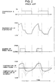
- FIG. 2 is a timing chart showing the timing and duration of operating elements according to the refrigerator shown in FIG. 1.
- FIG. 2 there are shown the temperature of the evaporator 1 with the compressor and fan being activated and not activated, state (open or close) of damper 11 of fresh room 7, the temperature in the fresh room 7 and the temperature of the cooled air blowing into the fresh room 7.
- the temperature inside the refrigerator especially the fresh room fluctuates undesirably, and the food placed near the cooled-air blowout opening is undesirably frozen, Moreover, the evaporator efficiency is deteriorated and the heat exchanging portion becomes frosted.
- the object of the present invention to provide a refrigerator in which electricity-saving operation and an improved food storage capability are realized by smoothing the temperature inside the refrigerator. Moreover, the object of the invention includes to improve the efficiency of heat exchanging and to prevent a heat-exchanging portion from being frosted.
- the invention relates to a refrigerator as initially defined and is characterised by heat exchanging means for exchanging heat between the cooled air flowing through the flow-in passage and the chilled air flowing through the flow-out passage.
- FIG. 1 is a schematic diagram showing a construction of the conventional refrigerator.
- FIG. 2 is a timing chart showing the timing and duration of operating elements according to the refrigerator shown in FIG. 1.
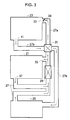
- FIG. 3 is a construction diagram according to an embodiment for the present invention.
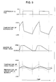
- FIG. 4 is a timing diagram illustrating relation between activation (and no-activation) of the compressor and damper in terms of temperature in the fresh room.
- FIG. 5 illustrate another configuration example for the novel refrigerator according to the second embodiment of the present invention.
- FIG. 6 is a cross sectional view of the refrigerator according to the third embodiment of the present invention.
- FIG. 7 illustrates a refrigerator employing a total heat exchanger as a heat exchanging means.
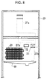
- FIG. 8 is cross sectional front view of the refrigerator utilizing the novel heat-exchaging means where the discharge duct 27b for discharging the air from the fresh room and the drain pan 49 are elongated.
- FIG. 9 is a timing diagram for a refrigerator where the damper 33 for the fresh room 23 is provided such that an openness degree of the damper 33 is continuously and steplessly controlled instead of being either open or closed.
- a basic configuration for a novel refrigerator is characterized in that there is provided a heat exchanging means between a cooled air flowing through a circulating passage to and from an evaporator and a chilled air flowing through a passage connected to and from a refrigerating room, as shown in FIG. 3.
- the evaporator serves to heat-exchanging between a cooling cycle and an air
- the heat exchanging means serves to heat-exchange between an air from the refrigerating room and the air from the evaporator.
- FIG. 3 is a construction diagram according to an embodiment for the present invention where a freezing room 21 is provided and disposed between a fresh room 23 and a vegetable room 25.
- the refrigerator comprises the freezing room 21, the fresh room 23, the vegetable room 25, ducts 27a, 27b, an evaporator 29, a heat exchanger 31 and a damper 33.
- Arrow marks in FIG. 3 show directions of air flow.
- the temperature of cooled air transferred into the freezing room 21 by a compressor is determined by evaporation temperature of the evaporator 29.
- the cooled air generated from evaporation at the evaporator 29 is fed to inside of the freezing room 21 through a cooled-air blowout opening 35 connected to a duct 27.
- the cooled air freezes an object or food disposed in the freezing room 21.
- the cooled air that has been used for freezing the food and whose temperature is increased, is discharged from a cooled-air discharge opening 37 and is then returned to the evaporator 29.
- cooling mechanism for the fresh room 23 is as follows. There is provided a freely open-closable damper 33 in a cooled-air blowout opening 39.
- a cooled-air circulating passage is constituted by a cooled-air blowout duct 27a for receiving the intake of the cooled air from a heat exchanger 31 and for connecting to the fresh room 23, and a discharge duct 27b for discharging the air from the fresh room 23.
- Both the blowout duct 27a and the discharge duct 27b are connected to the heat exchanger 31.
- the cooled air fed to the fresh room 23 cools an object such as food placed in the fresh room 23 and is discharged from a discharge opening 41 through which the air is discharged from the fresh room 23.
- the cooled air discharged from the discharge opening 41 flows to a vegetable room 25 through the discharge duct 27b.
- Both the discharge duct 27a for transferring the cooled air from the fresh room 23 and the blowout duct 27a for transferring the cooled air evaporated at evaporator 29 are connected to the heat exchanger 31.
- the cooled air blown out to the fresh room 23 and the cooled air discharged from the fresh room 23 are heat-exchanged in the heat exchanger 31.
- the temperature of the cooled air discharged from the fresh room is decreased; namely, the cooled air which cools the vegetable room 25 and returns to the evaporator 29 is decreased.
- the temperature of the cooled air blown into the fresh room 23 is increased, so that a temperature difference between the cooled air blown into the fresh room 23 and the air blown out of the fresh room 23 is desirably decreased to keep a preselected temperature of the fresh room in a stable manner.
- the inside of the fresh room is not rapidly cooled but gradually and smoothly cooled so as to achieve a desired cooling of the fresh room 23. Then, the duration in which is damper 33 is opened is made longer.
- FIG. 4 is a timing diagram illustrating relation between activation (and no-activation) of the compressor and damper in terms of temperature in the fresh room.
- the duration of a low temperature of the evaporator is longer during the operation of the compressor and the fan.
- the low temperature is not too quickly obtained then.
- the open duration of the damper 33 is loner. Since the blowout air that enters into the fresh room 23 and the discharge air that blows out of the fresh room 23 are heat-exchanged, the temperature difference between the blowout temperature in the fresh room 23 and the preselected temperature of the refrigerator is minimized, so that the temperature within the fresh room 23 is optimally smoothed up.
- FIG. 9 is a timing diagram for a refrigerator where the damper 33 for the fresh room 23 is provided such that an openness degree of the damper 33 is continuously controlled instead of being either open or closed.
- the temperature for the fresh room 23 can be further accurately controlled so as to further minimize the temperature difference between the blowout temperature in the fresh room and the preselected temperature of the refrigerator.
- the blowout air entering to the fresh room and the returned air blowing out of the fresh room are heat-exchanged in a passage between the fresh room and the freezing room.
- the temperature of the blowout air entering to the fresh room is increased, while the returned air returning toward the evaporator is decreased, so that a load for the compressor is significantly decreased thus achieving an energy-conserving operation.
- FIG. 5 illustrate another configuration example for the novel refrigerator according to the second embodiment of the present invention.
- the cooled-air blowout duct 27a for transferring the cooled-air into the fresh room 23, and the cooled-air discharge duct 27b for discharging the cooled-air from the fresh room 23 are disposed adjacent to each other with a heat conductive partition wall 43 interposed therebetween.
- the blowout duct 27a, the discharge duct 27b and the partition wall 43 and the inside of the refrigerator are arranged and configured in this order.
- the heat conductive partition wall 43 may be made of a thin resin material to achieve a good heat conductivity.
- an arrow mark of solid line designates the direction of blowout cooled air, whereas an arrow mark of dotted line is the discharged cooled air.
- the blowout duct 27a for transferring the cooled air into the fresh room 23 is preferably provided in a side of the refrigerator whose temperature is lower than outside thereof so as to minimize the heat loss.
- the still cooled air had better be discharged toward inside the refrigerator so as to achieve an effective use of the cooled air.
- FIG. 6 is a cross sectional view of the refrigerator according to the third embodiment of the present invention.
- the reference numeral 45 denotes a door for the storage room (fresh room 23).
- the heat pipe 47 is a pipe that transferrs the heat, for example, the heat is transferred by a change of specific gravity due to a phase change of refrigerant.
- an end 47a of the heat pipe 47 is provided within the blowout duct 27a, and other end 47b is provided within the discharge duct 27b.
- the cooled air blowing to the fresh room 23 and the cooled air discharged from the fresh room are heat-exchanged efficiently.
- FIG. 7 illustrates a refrigerator employing a total heat exchanger 53 as a heat exchanging means.
- the total heat exchanger 53 as the heat exchanging means which heat-exchanges between the blowout opening 27a for blowing the cooled air into the fresh room and the discharge opening 27b for blowing out the cooled air from the fresh air.
- the total heat exchanger 53 not only heat-exchanges between the blowout cooled air and the discharged cooled air, but also removes humidity from the cooled air discharged from the fresh room.
- a drain pan 49 can be made compact-sized, and the discharge duct 27b for discharging the air from the fresh room is unnecessarily elongated.
- the humidity taken away from the discharge duct 27b is guided from the blowout duct 27 into the inside of the fresh room 23, so that drying of the fresh room 23 is avoided.
- FIG. 8 is cross sectional front view of the refrigerator utilizing the novel heat-exchaging means where the discharge duct 27b for discharging the air from the fresh room and the drain pan 49 are elongated.
- the drain pan 49 below the evaporator 29, where the drain pan stores a dew drop.
- the elongated drain pan 49 is also located right below an end of the discharge duct 27b extended vertically downward from the heat exchanger 31.
- the reference numeral 51 indicates an intake opening that is provided for sucking air cooled by the evaporator 29 and is connected to the fresh room.
- the drain pan can receives such a discharged dew so as to safely collect the dew drop.
- the heat exchanging means serving to heat-exchange between the blow-in air and the discharged air is provided with respect to the fresh room in the above embodiments, it shall be appreciated that the heat exchanging means may be provided in the blow-in passage and the discharged duct with respect to the vegetable room and a bottle room (which stores soft drink or the like).
- the open-close damper 33 may be an air-flow-rate adjusting means which continuously and steplessly changes the air flow rate by open degree of the damper responsive to the temperature of the fresh room.
- the temperature at the blowout opening (or flow-in opening through which the cooled air is fed to the fresh room) is increased, while the temperature at the discharge opening (through which the cooled air is discharged from the fresh room) is decreased.
- the temperature difference therebetween is decreased so that the fresh room is smoothly and uniformly cooled instead of being cooled too quickly.
- the open duration of the damper is made longer, so that a temperature smoothing effect within the refrigerating room is optimized.
Landscapes
- Engineering & Computer Science (AREA)
- Chemical & Material Sciences (AREA)
- Combustion & Propulsion (AREA)
- Physics & Mathematics (AREA)
- Mechanical Engineering (AREA)
- Thermal Sciences (AREA)
- General Engineering & Computer Science (AREA)
- Cold Air Circulating Systems And Constructional Details In Refrigerators (AREA)
Description
- The present invention relates to a refrigerator comprising: an evaporator, a freezing room, a circulating passage connecting the evaporator to the freezing room for circulating air cooled by the evaporator to the freezing room, a storage room in which a temperature is to be set higher than that of the freezing room, a flow-in passage connected to the storage room for circulating air cooled by the evaporator to the storage room, and a flow-out passage, connected to the storage room, for chilled air flowing out of the storage room. Such a refrigerator is disclosed in EP-A-O 478 122.
- FIG. 1 is a schematic diagram showing the construction of the conventional refrigerator.
- Referring to FIG. 1, the conventional refrigerator consists of an evaporator 1, a
duct 3, afreezing room 5, afresh room 7, avegetable room 9 and adamper 11. The temperature of the evaporator 1 is set below the temperature of thefreezing room 5. High-temperature air is cooled by a compressor and a fan (not shown), so that the cooled air is distributed to thefreezing room 5 and thefresh room 7. The air output from each room is returned to the evaporator 1 through theduct 3 and is again cooled by the evaporator 1. - The
fresh room 7 and thevegetable room 9 are cooled in a manner that the cooling degree therefor is controlled by an open-close ofdamper 11. The cooled air flows through thefresh room 7 and the vegetable room in this order. The flow directions of the air are shown by arrow marks in FIG. 1. - Note that the
freezing room 5 has the lowest temperature, thefresh room 7 has the temperature that is slightly higher than thefreezing room 5, and thevegetable room 9 has the temperature that is slightly higher than thefresh room 7. - FIG. 2 is a timing chart showing the timing and duration of operating elements according to the refrigerator shown in FIG. 1.
- In FIG. 2, there are shown the temperature of the evaporator 1 with the compressor and fan being activated and not activated, state (open or close) of
damper 11 offresh room 7, the temperature in thefresh room 7 and the temperature of the cooled air blowing into thefresh room 7. - Referring to FIGS. 1 and 2, when the compressor and the fan are switched ON, the temperature of the evaporator 1 is decreased. Then, the
damper 11 is opened before the compressor and the fan are operated ON. Thus, the cooled air enters into thefresh room 7. Thereafter, when thefresh room 7 is sufficiently cooled, thedamper 11 is closed so that the cooled air from the evaporator 1 does not enter into thefresh room 7. In other words, by shutting off the cooled air entering thefresh room 7, the temperature of thefresh room 7 is controlled. - However, in the conventional refrigerator, there are caused the following problems:
- (1) The cooled air for cooling the
fresh room 7 has the same temperature with the cooled air for cooling thefreezing room 5. Thus, the passage for the cooled air to pass through thefresh room 7 is controlled by opening and closing the passage, in order that the the temperature of thefresh room 7 is kept at a suitable temperature. As a result thereof, the temperatures in the refrigerator, especially thefresh room 7 fluctuates with a undesirably big range, in other words, difference between the maximum and minimum temperatures of thefresh room 7 is too much to be suitable. Moreover, there occurs different temperature distribution inside the fresh room. - (2) Since the temperature of the cooled air blowing into the fresh room is too low, so that the food placed near a blowout opening tends to be frozen.
- (3) The circulated air from each room is returned to the evaporator 1 through each different passage. Therefore, each returned air has different state of own, thus creating undesirable dispersion of conditions when each circulated air is returned to the evaporator 1. As a result, the efficiency for the evaporator 1 is deteriorated and a heat exchanging portion is frosted.
- As described above, in the conventional refrigerators, the temperature inside the refrigerator especially the fresh room fluctuates undesirably, and the food placed near the cooled-air blowout opening is undesirably frozen, Moreover, the evaporator efficiency is deteriorated and the heat exchanging portion becomes frosted.
- In view of the foregoing drawbacks, it is therefore an object of the present invention to provide a refrigerator in which electricity-saving operation and an improved food storage capability are realized by smoothing the temperature inside the refrigerator. Moreover, the object of the invention includes to improve the efficiency of heat exchanging and to prevent a heat-exchanging portion from being frosted.
- The invention relates to a refrigerator as initially defined and is characterised by heat exchanging means for exchanging heat between the cooled air flowing through the flow-in passage and the chilled air flowing through the flow-out passage.
- The present invention will be better understood by referring, by way of example, to the accompanying drawings, in which:
- FIG. 1 is a schematic diagram showing a construction of the conventional refrigerator.
- FIG. 2 is a timing chart showing the timing and duration of operating elements according to the refrigerator shown in FIG. 1.
- FIG. 3 is a construction diagram according to an embodiment for the present invention.
- FIG. 4 is a timing diagram illustrating relation between activation (and no-activation) of the compressor and damper in terms of temperature in the fresh room.
- FIG. 5 illustrate another configuration example for the novel refrigerator according to the second embodiment of the present invention.
- FIG. 6 is a cross sectional view of the refrigerator according to the third embodiment of the present invention.
- FIG. 7 illustrates a refrigerator employing a total heat exchanger as a heat exchanging means.
- FIG. 8 is cross sectional front view of the refrigerator utilizing the novel heat-exchaging means where the
discharge duct 27b for discharging the air from the fresh room and thedrain pan 49 are elongated. - FIG. 9 is a timing diagram for a refrigerator where the
damper 33 for thefresh room 23 is provided such that an openness degree of thedamper 33 is continuously and steplessly controlled instead of being either open or closed. - A basic configuration for a novel refrigerator is characterized in that there is provided a heat exchanging means between a cooled air flowing through a circulating passage to and from an evaporator and a chilled air flowing through a passage connected to and from a refrigerating room, as shown in FIG. 3. As will be described below, the evaporator serves to heat-exchanging between a cooling cycle and an air, whereas the heat exchanging means serves to heat-exchange between an air from the refrigerating room and the air from the evaporator.
- FIG. 3 is a construction diagram according to an embodiment for the present invention where a
freezing room 21 is provided and disposed between afresh room 23 and avegetable room 25. - Referring to FIG. 3, the refrigerator comprises the
freezing room 21, thefresh room 23, thevegetable room 25,ducts evaporator 29, aheat exchanger 31 and adamper 33. Arrow marks in FIG. 3 show directions of air flow. - Next, operation for the construction configured in FIG. 3 will be described.
- The temperature of cooled air transferred into the
freezing room 21 by a compressor (not shown) is determined by evaporation temperature of theevaporator 29. The cooled air generated from evaporation at theevaporator 29 is fed to inside of thefreezing room 21 through a cooled-air blowout opening 35 connected to aduct 27. The cooled air freezes an object or food disposed in thefreezing room 21. The cooled air that has been used for freezing the food and whose temperature is increased, is discharged from a cooled-air discharge opening 37 and is then returned to theevaporator 29. - Referring still to FIG. 3, cooling mechanism for the
fresh room 23 is as follows. There is provided a freely open-closable damper 33 in a cooled-air blowout opening 39. A cooled-air circulating passage is constituted by a cooled-air blowout duct 27a for receiving the intake of the cooled air from aheat exchanger 31 and for connecting to thefresh room 23, and adischarge duct 27b for discharging the air from thefresh room 23. Both theblowout duct 27a and thedischarge duct 27b are connected to theheat exchanger 31. In other words, the cooled air fed to thefresh room 23 cools an object such as food placed in thefresh room 23 and is discharged from a discharge opening 41 through which the air is discharged from thefresh room 23. - Then, the cooled air discharged from the discharge opening 41 flows to a
vegetable room 25 through thedischarge duct 27b. Both thedischarge duct 27a for transferring the cooled air from thefresh room 23 and theblowout duct 27a for transferring the cooled air evaporated atevaporator 29 are connected to theheat exchanger 31. By such a novel configuration demonstrated in FIG. 3, the cooled air blown out to thefresh room 23 and the cooled air discharged from thefresh room 23 are heat-exchanged in theheat exchanger 31. In other words, the temperature of the cooled air discharged from the fresh room is decreased; namely, the cooled air which cools thevegetable room 25 and returns to theevaporator 29 is decreased. - In the above structure and operation for the novel refrigerator, the temperature of the cooled air blown into the
fresh room 23 is increased, so that a temperature difference between the cooled air blown into thefresh room 23 and the air blown out of thefresh room 23 is desirably decreased to keep a preselected temperature of the fresh room in a stable manner. As a result, the inside of the fresh room is not rapidly cooled but gradually and smoothly cooled so as to achieve a desired cooling of thefresh room 23. Then, the duration in which isdamper 33 is opened is made longer. - FIG. 4 is a timing diagram illustrating relation between activation (and no-activation) of the compressor and damper in terms of temperature in the fresh room.
- Referring to FIG. 4, in comparison to FIG. 2 representing the conventional refrigerator, the duration of a low temperature of the evaporator is longer during the operation of the compressor and the fan. The low temperature is not too quickly obtained then. Thus, the open duration of the
damper 33 is loner. Since the blowout air that enters into thefresh room 23 and the discharge air that blows out of thefresh room 23 are heat-exchanged, the temperature difference between the blowout temperature in thefresh room 23 and the preselected temperature of the refrigerator is minimized, so that the temperature within thefresh room 23 is optimally smoothed up. - FIG. 9 is a timing diagram for a refrigerator where the
damper 33 for thefresh room 23 is provided such that an openness degree of thedamper 33 is continuously controlled instead of being either open or closed. By employing such a continuously controlleddamper 33, the temperature for thefresh room 23 can be further accurately controlled so as to further minimize the temperature difference between the blowout temperature in the fresh room and the preselected temperature of the refrigerator. - As described in detail above, the blowout air entering to the fresh room and the returned air blowing out of the fresh room are heat-exchanged in a passage between the fresh room and the freezing room. Thereby, the temperature of the blowout air entering to the fresh room is increased, while the returned air returning toward the evaporator is decreased, so that a load for the compressor is significantly decreased thus achieving an energy-conserving operation.
- FIG. 5 illustrate another configuration example for the novel refrigerator according to the second embodiment of the present invention.
- Referring to FIG. 5, the cooled-
air blowout duct 27a for transferring the cooled-air into thefresh room 23, and the cooled-air discharge duct 27b for discharging the cooled-air from thefresh room 23 are disposed adjacent to each other with a heatconductive partition wall 43 interposed therebetween. Theblowout duct 27a, thedischarge duct 27b and thepartition wall 43 and the inside of the refrigerator are arranged and configured in this order. The heatconductive partition wall 43 may be made of a thin resin material to achieve a good heat conductivity. In FIG. 5, an arrow mark of solid line designates the direction of blowout cooled air, whereas an arrow mark of dotted line is the discharged cooled air. - Reason for adopting the above configuration is to minimize a heat loss. The
blowout duct 27a for transferring the cooled air into thefresh room 23 is preferably provided in a side of the refrigerator whose temperature is lower than outside thereof so as to minimize the heat loss. In other words, instead of a case where the low-temperature air is discharged outside the refrigerator, the still cooled air had better be discharged toward inside the refrigerator so as to achieve an effective use of the cooled air. - FIG. 6 is a cross sectional view of the refrigerator according to the third embodiment of the present invention. In the same figure, the
reference numeral 45 denotes a door for the storage room (fresh room 23). - Referring to FIG. 6, there is provided a
heat pipe 47. Theheat pipe 47 is a pipe that transferrs the heat, for example, the heat is transferred by a change of specific gravity due to a phase change of refrigerant. In FIG. 6, anend 47a of theheat pipe 47 is provided within theblowout duct 27a, andother end 47b is provided within thedischarge duct 27b. - The operation for the refrigerator configured according to this second embodiment will now be described.
- There contains the refrigerant inside the sealed
heat pipe 47. Thereby, the refrigerant that takes away the heat in the liquid-side end 47a, becomes gaseous and is guided toother end 47b. Then, the heat is radiated in theother end 47b and the gaseous refrigerant becomes liquid so as to take away the heat. - In other words, in this third embodiment, the cooled air blowing to the
fresh room 23 and the cooled air discharged from the fresh room are heat-exchanged efficiently. - FIG. 7 illustrates a refrigerator employing a
total heat exchanger 53 as a heat exchanging means. - Referring to FIG. 7, there is provided the
total heat exchanger 53 as the heat exchanging means which heat-exchanges between theblowout opening 27a for blowing the cooled air into the fresh room and thedischarge opening 27b for blowing out the cooled air from the fresh air. Thetotal heat exchanger 53 not only heat-exchanges between the blowout cooled air and the discharged cooled air, but also removes humidity from the cooled air discharged from the fresh room. Thus, adrain pan 49 can be made compact-sized, and thedischarge duct 27b for discharging the air from the fresh room is unnecessarily elongated. - Moreover, the humidity taken away from the
discharge duct 27b is guided from theblowout duct 27 into the inside of thefresh room 23, so that drying of thefresh room 23 is avoided. - FIG. 8 is cross sectional front view of the refrigerator utilizing the novel heat-exchaging means where the
discharge duct 27b for discharging the air from the fresh room and thedrain pan 49 are elongated. - Referring to FIG. 8, there is provided the
drain pan 49 below theevaporator 29, where the drain pan stores a dew drop. Theelongated drain pan 49 is also located right below an end of thedischarge duct 27b extended vertically downward from theheat exchanger 31. In FIG. 8, thereference numeral 51 indicates an intake opening that is provided for sucking air cooled by theevaporator 29 and is connected to the fresh room. - By employing the above configuration shown in FIG. 8, when the fan is stopped, a door (not shown) of the refrigerator is opened and the inside of the
discharge duct 27b is bedewed, the drain pan can receives such a discharged dew so as to safely collect the dew drop. - Though the heat exchanging means serving to heat-exchange between the blow-in air and the discharged air is provided with respect to the fresh room in the above embodiments, it shall be appreciated that the heat exchanging means may be provided in the blow-in passage and the discharged duct with respect to the vegetable room and a bottle room (which stores soft drink or the like).
- It shall be appreciated that the open-
close damper 33 may be an air-flow-rate adjusting means which continuously and steplessly changes the air flow rate by open degree of the damper responsive to the temperature of the fresh room. - In summary, by employing the novel refrigerator according to the present invention, the temperature at the blowout opening (or flow-in opening through which the cooled air is fed to the fresh room) is increased, while the temperature at the discharge opening (through which the cooled air is discharged from the fresh room) is decreased. As a result thereof, the temperature difference therebetween is decreased so that the fresh room is smoothly and uniformly cooled instead of being cooled too quickly. In other words, the open duration of the damper is made longer, so that a temperature smoothing effect within the refrigerating room is optimized.
Claims (8)
- A refrigerator comprising:an evaporator (29);a freezing room (21);a circulating passage connecting the evaporator (29) to the freezing room (21) for circulating air cooled by the evaporator to the freezing room (21);a first storage room (23) in which a temperature is to be set higher than that of the freezing room;a flow-in passage (27a) connected to the storage room (23) for circulating air cooled by the evaporator (29) to the storage room; anda flow-out passage (27b), connected to the storage room (23), for chilled air flowing out of the storage room (23);characterised by:
heat exchanging means (31) for exchanging heat between the cooled air flowing through the flow-in passage (27a) and the chilled air flowing through the flow-out passage (27b). - The refrigerator of claim 1, further comprising a second storage room (25) in which a temperature thereof is to be set higher than that of the first storage room (23), wherein said flow-out passage (27b) is connected to feed air that is heat-exchanged in the heat exchanging means (31) to the second storage room (25) and wherein a duct (27) is connected to feed air flowing out of the second storage room back to the evaporator (29).
- The refrigerator of claim 1 or 2, wherein the first storage room (23) is equipped with a member (33) that is arranged to adjust a flow rate of the cooled air entering to the first storage room (23) in such manner that the flow rate is steplessly controlled.
- The refrigerator of any preceding claim, wherein the flow-in passage (27a) and flow-out passage (27b) are disposed adjacent to each other with a heat-conductive partition member (43) interposed therebetween.
- The refrigerator of claim 4, wherein the flow-in and flow-out passages (27a, 27b) are so arranged that the directions of air flow in the flow-in passage (27a) and the flow-out passage (27b) are opposite to each other.
- The refrigerator of claim 4 or 5, wherein the flow-out passage (27b) is provided facing outside the refrigerator, while the flow-in passage (27a) is provided facing inside the refrigerator.
- The refrigerator of any one of claims 1 to 3, wherein the heat exchanging means includes a heat pipe (47).
- The refrigerator of any one of claims 1 to 3, wherein a total heat exchanger (53) for removing humidity serves as the heat exchanging means.
Applications Claiming Priority (2)
| Application Number | Priority Date | Filing Date | Title |
|---|---|---|---|
| JP37219/93 | 1993-02-26 | ||
| JP5037219A JPH06249562A (en) | 1993-02-26 | 1993-02-26 | Freezer refrigerator |
Publications (3)
| Publication Number | Publication Date |
|---|---|
| EP0612965A2 EP0612965A2 (en) | 1994-08-31 |
| EP0612965A3 EP0612965A3 (en) | 1994-10-19 |
| EP0612965B1 true EP0612965B1 (en) | 1997-10-22 |
Family
ID=12491484
Family Applications (1)
| Application Number | Title | Priority Date | Filing Date |
|---|---|---|---|
| EP94102717A Expired - Lifetime EP0612965B1 (en) | 1993-02-26 | 1994-02-23 | Refrigerator with heat exchanger optimally configured |
Country Status (6)
| Country | Link |
|---|---|
| US (1) | US5497634A (en) |
| EP (1) | EP0612965B1 (en) |
| JP (1) | JPH06249562A (en) |
| KR (1) | KR940020076A (en) |
| DE (1) | DE69406328T2 (en) |
| TW (1) | TW232047B (en) |
Families Citing this family (17)
| Publication number | Priority date | Publication date | Assignee | Title |
|---|---|---|---|---|
| KR960001695A (en) * | 1994-06-22 | 1996-01-25 | 이헌조 | Cold air circulation system of the refrigerator |
| WO1996007859A1 (en) * | 1994-09-07 | 1996-03-14 | General Electric Company | Refrigerator multiplex damper system |
| US6058734A (en) * | 1998-12-15 | 2000-05-09 | Daewoo Electronics Co., Ltd. | Refrigerator provided with cooled air bypass passages |
| US7748080B2 (en) * | 2007-01-17 | 2010-07-06 | Sub-Zero, Inc. | Hinge and closure device for refrigerator |
| US7735943B2 (en) * | 2007-01-17 | 2010-06-15 | Sub-Zero, Inc. | Hinged access panel for refrigerated appliance |
| GB2531365B (en) * | 2014-12-23 | 2017-01-11 | Flint Eng Ltd | Heat transfer apparatus |
| CN105806005A (en) * | 2014-12-31 | 2016-07-27 | 松下电器研究开发(苏州)有限公司 | Refrigerator |
| CN107289706A (en) * | 2016-03-31 | 2017-10-24 | 松下知识产权经营株式会社 | Refrigerator |
| CN108332487A (en) * | 2017-01-20 | 2018-07-27 | 松下知识产权经营株式会社 | Refrigerator |
| DE102017201232A1 (en) * | 2017-01-26 | 2018-07-26 | BSH Hausgeräte GmbH | Refrigerating appliance with branched air duct |
| CN107477922A (en) * | 2017-07-25 | 2017-12-15 | 青岛海尔股份有限公司 | Single system wind cooling refrigerator |
| CN107687733A (en) * | 2017-07-25 | 2018-02-13 | 青岛海尔股份有限公司 | Single system wind cooling refrigerator |
| CN107504742A (en) * | 2017-07-25 | 2017-12-22 | 青岛海尔股份有限公司 | Single system wind cooling refrigerator |
| CN107421167A (en) * | 2017-07-25 | 2017-12-01 | 青岛海尔股份有限公司 | Single system wind cooling refrigerator |
| CN107270626A (en) * | 2017-07-25 | 2017-10-20 | 青岛海尔股份有限公司 | Single system wind cooling refrigerator |
| WO2020008970A1 (en) * | 2018-07-03 | 2020-01-09 | シャープ株式会社 | Refrigerator |
| CN111854265B (en) * | 2019-04-30 | 2022-06-14 | 松下电器研究开发(苏州)有限公司 | Refrigerator and control method thereof |
Family Cites Families (3)
| Publication number | Priority date | Publication date | Assignee | Title |
|---|---|---|---|---|
| US3375677A (en) * | 1967-01-03 | 1968-04-02 | Gen Motors Corp | Method and apparatus for maintaining high humidity in a frost-free domestic refrigerator |
| US4211090A (en) * | 1978-12-06 | 1980-07-08 | General Electric Company | Household refrigerator with air circulation and cooling arrangement |
| AU636497B2 (en) * | 1990-09-27 | 1993-04-29 | Mitsubishi Denki Kabushiki Kaisha | Refrigerator with a frozen food compartment |
-
1993
- 1993-02-26 JP JP5037219A patent/JPH06249562A/en active Pending
-
1994
- 1994-02-16 TW TW083101246A patent/TW232047B/zh active
- 1994-02-17 US US08/197,973 patent/US5497634A/en not_active Expired - Fee Related
- 1994-02-23 DE DE69406328T patent/DE69406328T2/en not_active Expired - Fee Related
- 1994-02-23 EP EP94102717A patent/EP0612965B1/en not_active Expired - Lifetime
- 1994-02-25 KR KR1019940003392A patent/KR940020076A/en not_active Ceased
Also Published As
| Publication number | Publication date |
|---|---|
| US5497634A (en) | 1996-03-12 |
| KR940020076A (en) | 1994-09-15 |
| EP0612965A2 (en) | 1994-08-31 |
| TW232047B (en) | 1994-10-11 |
| EP0612965A3 (en) | 1994-10-19 |
| DE69406328D1 (en) | 1997-11-27 |
| DE69406328T2 (en) | 1998-03-12 |
| JPH06249562A (en) | 1994-09-06 |
Similar Documents
| Publication | Publication Date | Title |
|---|---|---|
| US5497634A (en) | Refrigerator with heat exchanger optimally configured | |
| US7137266B2 (en) | Time division multi-cycle type cooling apparatus and method for controlling the same | |
| JP3184775B2 (en) | Refrigerator with a function of discharging cool air from doors using an air curtain generator | |
| JP5530852B2 (en) | refrigerator | |
| JP6074596B2 (en) | refrigerator | |
| JP2002504662A (en) | refrigerator | |
| KR20120023699A (en) | Refrigerator | |
| JP2000009372A (en) | Freezer refrigerator | |
| CN101266094B (en) | Refrigerator | |
| JP4206792B2 (en) | refrigerator | |
| CN110094917B (en) | refrigerator | |
| JP5363247B2 (en) | refrigerator | |
| JP3049425B2 (en) | Refrigerator with two evaporators | |
| JPH10300316A (en) | Refrigerator having freezer | |
| JP4739926B2 (en) | refrigerator | |
| JP2019132506A (en) | refrigerator | |
| JP2000283626A (en) | refrigerator | |
| JP4103384B2 (en) | refrigerator | |
| JP2017026210A (en) | refrigerator | |
| JP2019027649A (en) | refrigerator | |
| CN1779394B (en) | Refrigerator and operation control method thereof | |
| KR101872608B1 (en) | Refrigerator | |
| KR100678777B1 (en) | Refrigerator | |
| JP7696239B2 (en) | refrigerator | |
| JP2000356445A (en) | refrigerator |
Legal Events
| Date | Code | Title | Description |
|---|---|---|---|
| PUAI | Public reference made under article 153(3) epc to a published international application that has entered the european phase |
Free format text: ORIGINAL CODE: 0009012 |
|
| PUAL | Search report despatched |
Free format text: ORIGINAL CODE: 0009013 |
|
| 17P | Request for examination filed |
Effective date: 19940223 |
|
| AK | Designated contracting states |
Kind code of ref document: A2 Designated state(s): DE FR GB IT |
|
| AK | Designated contracting states |
Kind code of ref document: A3 Designated state(s): DE FR GB IT |
|
| 17Q | First examination report despatched |
Effective date: 19960118 |
|
| GRAG | Despatch of communication of intention to grant |
Free format text: ORIGINAL CODE: EPIDOS AGRA |
|
| GRAH | Despatch of communication of intention to grant a patent |
Free format text: ORIGINAL CODE: EPIDOS IGRA |
|
| GRAH | Despatch of communication of intention to grant a patent |
Free format text: ORIGINAL CODE: EPIDOS IGRA |
|
| GRAA | (expected) grant |
Free format text: ORIGINAL CODE: 0009210 |
|
| RAP1 | Party data changed (applicant data changed or rights of an application transferred) |
Owner name: TOSHIBA AVE CO., LTD Owner name: KABUSHIKI KAISHA TOSHIBA |
|
| AK | Designated contracting states |
Kind code of ref document: B1 Designated state(s): DE FR GB IT |
|
| REF | Corresponds to: |
Ref document number: 69406328 Country of ref document: DE Date of ref document: 19971127 |
|
| ET | Fr: translation filed | ||
| ITF | It: translation for a ep patent filed | ||
| PGFP | Annual fee paid to national office [announced via postgrant information from national office to epo] |
Ref country code: FR Payment date: 19980210 Year of fee payment: 5 |
|
| PGFP | Annual fee paid to national office [announced via postgrant information from national office to epo] |
Ref country code: GB Payment date: 19980216 Year of fee payment: 5 |
|
| PGFP | Annual fee paid to national office [announced via postgrant information from national office to epo] |
Ref country code: DE Payment date: 19980302 Year of fee payment: 5 |
|
| PLBE | No opposition filed within time limit |
Free format text: ORIGINAL CODE: 0009261 |
|
| STAA | Information on the status of an ep patent application or granted ep patent |
Free format text: STATUS: NO OPPOSITION FILED WITHIN TIME LIMIT |
|
| 26N | No opposition filed | ||
| PG25 | Lapsed in a contracting state [announced via postgrant information from national office to epo] |
Ref country code: GB Free format text: LAPSE BECAUSE OF NON-PAYMENT OF DUE FEES Effective date: 19990223 |
|
| GBPC | Gb: european patent ceased through non-payment of renewal fee |
Effective date: 19990223 |
|
| PG25 | Lapsed in a contracting state [announced via postgrant information from national office to epo] |
Ref country code: FR Free format text: LAPSE BECAUSE OF NON-PAYMENT OF DUE FEES Effective date: 19991029 |
|
| PG25 | Lapsed in a contracting state [announced via postgrant information from national office to epo] |
Ref country code: DE Free format text: LAPSE BECAUSE OF NON-PAYMENT OF DUE FEES Effective date: 19991201 |
|
| REG | Reference to a national code |
Ref country code: FR Ref legal event code: ST |
|
| PG25 | Lapsed in a contracting state [announced via postgrant information from national office to epo] |
Ref country code: IT Free format text: LAPSE BECAUSE OF NON-PAYMENT OF DUE FEES;WARNING: LAPSES OF ITALIAN PATENTS WITH EFFECTIVE DATE BEFORE 2007 MAY HAVE OCCURRED AT ANY TIME BEFORE 2007. THE CORRECT EFFECTIVE DATE MAY BE DIFFERENT FROM THE ONE RECORDED. Effective date: 20050223 |