EP0612395B1 - Rotary drum dryer having internal flights - Google Patents
Rotary drum dryer having internal flights Download PDFInfo
- Publication number
- EP0612395B1 EP0612395B1 EP92922001A EP92922001A EP0612395B1 EP 0612395 B1 EP0612395 B1 EP 0612395B1 EP 92922001 A EP92922001 A EP 92922001A EP 92922001 A EP92922001 A EP 92922001A EP 0612395 B1 EP0612395 B1 EP 0612395B1
- Authority
- EP
- European Patent Office
- Prior art keywords
- drum
- aggregate
- flights
- rotary drum
- wall
- Prior art date
- Legal status (The legal status is an assumption and is not a legal conclusion. Google has not performed a legal analysis and makes no representation as to the accuracy of the status listed.)
- Expired - Lifetime
Links
- 230000010006 flight Effects 0.000 title claims abstract description 59
- 238000002485 combustion reaction Methods 0.000 claims abstract description 31
- 238000010438 heat treatment Methods 0.000 claims description 8
- 230000033001 locomotion Effects 0.000 claims description 5
- 238000011144 upstream manufacturing Methods 0.000 claims description 5
- 238000004140 cleaning Methods 0.000 claims description 3
- 230000006866 deterioration Effects 0.000 abstract description 5
- 239000002184 metal Substances 0.000 abstract description 5
- 239000010426 asphalt Substances 0.000 abstract description 4
- 238000004519 manufacturing process Methods 0.000 abstract description 3
- 239000000203 mixture Substances 0.000 abstract description 3
- 238000010276 construction Methods 0.000 abstract 1
- 239000007789 gas Substances 0.000 description 9
- 230000000717 retained effect Effects 0.000 description 3
- 239000004575 stone Substances 0.000 description 3
- 238000001914 filtration Methods 0.000 description 2
- 230000004323 axial length Effects 0.000 description 1
- 238000001035 drying Methods 0.000 description 1
- 239000000446 fuel Substances 0.000 description 1
- 238000009434 installation Methods 0.000 description 1
- 238000002955 isolation Methods 0.000 description 1
- 239000007788 liquid Substances 0.000 description 1
- 238000013021 overheating Methods 0.000 description 1
- 230000001681 protective effect Effects 0.000 description 1
Images

Classifications
-
- E—FIXED CONSTRUCTIONS
- E01—CONSTRUCTION OF ROADS, RAILWAYS, OR BRIDGES
- E01C—CONSTRUCTION OF, OR SURFACES FOR, ROADS, SPORTS GROUNDS, OR THE LIKE; MACHINES OR AUXILIARY TOOLS FOR CONSTRUCTION OR REPAIR
- E01C19/00—Machines, tools or auxiliary devices for preparing or distributing paving materials, for working the placed materials, or for forming, consolidating, or finishing the paving
- E01C19/02—Machines, tools or auxiliary devices for preparing or distributing paving materials, for working the placed materials, or for forming, consolidating, or finishing the paving for preparing the materials
- E01C19/05—Crushing, pulverising or disintegrating apparatus; Aggregate screening, cleaning, drying or heating apparatus; Dust-collecting arrangements specially adapted therefor
-
- F—MECHANICAL ENGINEERING; LIGHTING; HEATING; WEAPONS; BLASTING
- F26—DRYING
- F26B—DRYING SOLID MATERIALS OR OBJECTS BY REMOVING LIQUID THEREFROM
- F26B11/00—Machines or apparatus for drying solid materials or objects with movement which is non-progressive
- F26B11/02—Machines or apparatus for drying solid materials or objects with movement which is non-progressive in moving drums or other mainly-closed receptacles
- F26B11/04—Machines or apparatus for drying solid materials or objects with movement which is non-progressive in moving drums or other mainly-closed receptacles rotating about a horizontal or slightly-inclined axis
- F26B11/0463—Machines or apparatus for drying solid materials or objects with movement which is non-progressive in moving drums or other mainly-closed receptacles rotating about a horizontal or slightly-inclined axis having internal elements, e.g. which are being moved or rotated by means other than the rotating drum wall
- F26B11/0477—Machines or apparatus for drying solid materials or objects with movement which is non-progressive in moving drums or other mainly-closed receptacles rotating about a horizontal or slightly-inclined axis having internal elements, e.g. which are being moved or rotated by means other than the rotating drum wall for mixing, stirring or conveying the materials to be dried, e.g. mounted to the wall, rotating with the drum
Definitions
- the present invention relates to a rotary drum dryer, comprising the features as indicated in the preamble of claim 1 and particularly, but not exclusively to such a dryer for heating and drying stone aggregate useful in the production of asphalt paving composition or the like.
- a dryer is known from US-A-4 300 837.
- Conventional asphalt production plants include a drum dryer wherein the stone aggregate is heated and dried and then mixed with liquid asphalt.
- Such dryers typically comprise a rotating drum which is inclined from the horizontal.
- the virgin aggregate is introduced into the upper end of the drum, and an outlet is provided adjacent the lower end of the drum for withdrawing the heated and dried aggregate.
- a burner is mounted adjacent one end of the drum so as to create a heated gas stream which moves through the drum to heat the aggregate flowing therethrough.
- a parallel flow dryer the burner is mounted adjacent the upper end of the drum so that the heated gas stream moves through the drum in a direction parallel to the moving aggregate, while in a counterflow drum dryer, the burner is mounted adjacent the lower end of the drum and the heated gas flows counter to the direction of movement of the aggregate.
- a dryer of the parallel flow type is disclosed in U.S. Patent No. 4,332,478 to Binz, and a dryer of the counterflow type is disclosed in U.S. Patent No. 4,867,572 to Brock et al.
- the burner flame defines a combustion zone, and a plurality of longitudinally extending flights extend about the circumference of the inside wall of the drum at the combustion zone, so that the flights shield the wall of the drum from the radiant heat of the burner flame and thereby protect the wall from overheating and deterioration.
- the need for a protective refractory lining is thus usually unnecessary.
- These flights are typically T-shaped in transverse cross section, and the flights are spaced from the wall so as to pass over the layer of aggregate in the bottom of the drum as the drum rotates. Thus the flights also tend to shield the aggregate from the radiant heat as the aggregate moves through the combustion zone.
- a rotary drum dryer comprising a hollow drum having a cylindrical wall and which is mounted for rotation about a central axis; means for rotating said drum about said central axis; aggregate inlet means for introducing aggregate into the interior of said drum and aggregate outlet means for withdrawing the aggregate from the interior of said drum, and so as to define a downstream direction when viewed in the direction of the movement of the aggregate from the inlet means toward the outlet means and an opposite upstream direction; heating means comprising a burner positioned adjacent an end of said drum for introducing air and a high temperature flame into the interior of said drum, and so as to define a combustion zone in said drum which surrounds said flame; a dam coaxially encircling the inside of said wall of said drum and defining an inside circumferential edge which is spaced from said wall of said drum; and a plurality of longitudinally extending flights mounted to the inside surface of wall and said flights being spaced about substantially the entire circumference of the inside surface of said wall of said drum and extending upstream of
- the combustion zone in the dryer disclosed in US 4300837 is provided with longitudinally extending baffleplates mounted on spiral blades extending radially inwardly from the inside surface of the drum wall. These baffleplates overlap so that the whole inside surface of the drum in this zone and the aggregate passing through the zone are shielded from the radiant heat of the burner flame in the manner discussed above.
- the dryer disclosed in US 4300837 has first and second said dams at axially spaced apart locations. One of these locations is at an exit end of the drum remote from the combustion zone and the other location is at the downstream end of an isolation zone of the dryer which itself is located downstream of the combustion zone thereof and in which the flights comprise lifter devices for lifting the aggregate up to the highest portion of the drum where the aggregate falls back across the whole area of the drum during rotation of the drum to form a screen across the whole area of the drum.
- An object of the invention is to permit more of the aggregate to be exposed to the radiant heat of the burner flame as it moves through the combustion zone to thereby increase the heat absorbed by the aggregate.
- a rotary drum dryer as defined in the last but three preceding paragraph and characterised in that (i) said dam is located adjacent the downstream end of said combustion zone, (ii) said flights extend along the length of said combustion zone, (iii) each of said flights, when viewed in transverse cross-section, comprises a medial portion which is generally perpendicular to a radial line extending from said central axis and a trailing edge portion which extends inclined away from said wall from said medial portion, and (iv) said dam is adapted to retain and raise the level of the aggregate flowing through said combustion zone so that the flights pass through the aggregate in the bottom of the drum in the combustion zone and collect a portion of the aggregate on their radially outwardly facing surfaces and carry the collected aggregate to an elevated discharge point.
- each of said flights when viewed in transverse cross-section, may be generally parallel to an adjacent portion of said inside circumferential edge of said dam, and in this case may lie at a level which generally corresponds to the level of the adjacent portion of said inside circumferential edge of said dam.
- this medial portion may be generally planar and define a plane which is substantially perpendicular to a radial line extending from said central axis.
- trailing edge portion of each of said flights extends from said plane of said medial portion at an angle of about 70°.
- Each of said flights may further comprise a leading edge portion which is positioned on the side of said medial portion opposite said trailing edge portion, said leading edge portion being inclined toward the wall of said drum.
- said leading edge portion extends from said plane of said medial portion at an angle of about 30 degrees.
- said leading edge portion and said trailing edge portion of each flight each have a transverse dimension which is about one half that of said medial portion.
- the flights may be equally spaced about the entire circumference of the inside surface of said cylindrical wall of said drum, and although not essential these flights may be positioned sufficiently close to each other that the inside surface of said cylindrical wall is substantially completely covered in the radial direction.
- the flights may be supported in spaced relation from the inside surface of said wall of said drum by a plurality of longitudinally spaced apart posts.
- the dam may comprise a plurality of aligned and interconnected plates, and a plurality of openings may extend through at least some of said plates immediately adjacent the inside surface of said wall of said drum to facilitate cleaning of the aggregate therefrom.
- the rotary drum dryer may further comprise lifting flight means mounted to that portion of said inside surface of said wall of said drum which is outside of said combustion zone for lifting and cascading the aggregate as it flows in the downstream direction through the interior of the drum on rotation thereof.
- the rotary drum dryer may comprise means mounting said drum for rotation about said central axis and with said central axis being inclined with respect to the horizontal so as to define an upper end and a lower end of said drum.
- the heating means When so mounted, (i) the heating means may be disposed adjacent said lower end of said drum and exhaust duct means may be positioned adjacent the upper end of said drum so that the aggregate moving through said drum in the downstream direction moves counter to the direction of gas flow through said drum, or (ii) the heating means may be disposed adjacent said upper end of said drum and exhaust duct means may be positioned adjacent said lower end of said drum so that the aggregate moving through said drum in the downstream direction moves parallel to the direction of gas flow through said drum.
- FIG. 1 schematically illustrates a rotary drum dryer 10 in accordance with one preferred embodiment of the present invention.
- the dryer 10 comprises an elongate hollow drum 12 having a cylindrical wall 14, and which defines a central axis 15 which is inclined with respect to the horizontal H so as to define an upper end 16 and a lower end 17 of the drum.
- the drum 12 is rotatably mounted on a frame by means of bearing sleeves 18 and so as to be rotatable about the central axis 15.
- a motor which is shown schematically in Figure 1 at 20 rotates the drum about the central axis in a conventional manner.
- An aggregate delivery conveyor 21 is positioned adjacent the upper end of the drum for introducing stone aggregate or the like into the interior of drum, and an aggregate outlet duct 22 is positioned at the lower end of the drum.
- a plurality of lifting flights 24 of conventional design are mounted on the inside of the drum and along the major portion of the axial length of the drum for lifting the aggregate and dropping the same through the interior of the dryer as it is rotated.
- the aggregate which is introduced into the drum via the inlet conveyor 21 is caused to cascade through the interior of the drum, and move toward the outlet duct.
- the drum dryer further includes a burner 26 which is mounted at the lower end of the drum for directing a high temperature flame into the interior of the drum.
- the burner 26 is of conventional design, and it includes a blower 27 which charges a mixture of fuel and air into the burner, where it is ignited to produce a flame for heating the interior of the drum.
- An exhaust air duct 28 is positioned at the upper end of the drum, for exhausting the heated gases from the drum and so that the heated gas flows through the drum to heat the cascading aggregate.
- the exhaust air flow may be conveyed through the duct to a conventional filtering baghouse (not shown) and then released to the atmosphere.
- the flame F of the burner defines a combustion zone in the drum which surrounds at least a substantial portion of the length of the flame, and in accordance with the present invention, a dam 30 is mounted to the inside wall of the drum in a coaxially encircling manner adjacent the downstream end of the combustion zone.
- the dam 30 comprises a plurality of aligned and interconnected metal plates, and it defines an inside circumferential edge 31 which is spaced from the wall of the drum. Also, in the illustrated embodiment, all of the plates of the dam 30 include an opening 32 adjacent the inside surface of the wall of the drum, to facilitate cleaning of the aggregate therefrom.
- Each of the combustion zone flights 34 when viewed in transverse cross section as seen in Figure 4, comprises a generally planar medial portion 36 having opposite side edges, a leading edge portion 38 extending from the leading side edge of the medial portion when viewed in the rotational direction of the drum, and a trailing edge portion 40 extending from the other side edge.
- the medial portion 36 when viewed in transverse cross section is generally perpendicular to a radial line extending from the central axis 15, and the medial portion 36 is aligned with the adjacent portion of the circumferential edge 31 of the dam 30 as best seen in Figure 2.
- leading edge portion 38 and the trailing edge portion 40 each have a transverse , dimension which is about one half that of the medial portion, and the leading edge portion 38 extends downwardly toward the wall of the drum at an angle A of about 30° from the plane of the medial portion, and the trailing edge portion 40 extends upwardly from the plane of the medial portion at an angle B of about 70°.
- the flights 34 are equally spaced about the entire circumference of the inside surface of the wall of the drum, and they are mounted to the drum by means of the posts 42. More particularly, the posts 42 comprise an angled metal member, and three or four of such posts are positioned in a longitudinally spaced apart arrangement along the length of each flight for mounting the flight to the wall of the drum. As best seen in Figure 3, the flights 34 are positioned sufficiently close to each other so that the inside wall of the drum is substantially completely covered in the radial direction. Thus the wall of the drum is substantially completely shielded from the radiant heat of the flame F in the combustion zone.
- the drum has a diameter of about eight feet (2.44m) and a longitudinal length of about forty feet (12.19m).
- the combustion zone flights 34 have a longitudinal length of about ten feet (3.05m), and the media portions have a width C ( Figure 3) of about six inches (152 mm).
- the leading edge portion 38 of each flight has a width D of about three inches (76 mm), and the trailing edge portion 40 of each flight has a width E of about three inches (76 mm).
- the dam 30 has a radial height of about six inches (152 mm).
- the aggregate In operation, the aggregate is continuously introduced into the upper end of the rotating drum by the inlet conveyor 21, and the aggregate cascades through the interior of the drum and moves toward the outlet duct 22 at the lower end 17. Also, with the burner 26 in operation, heated gases flow through the length of the drum in a direction counter to the direction of movement of the aggregate and exhausts through the outlet duct 28 to the filtering baghouse.
- the dam 30 is located adjacent the downstream end of the combustion zone when viewed in the direction of movement of the aggregate, and it serves to retain the aggregate in the combustion zone and to cause the level of the aggregate to rise so that the flights move through the aggregate which is in the bottom of the drum and collect a portion of the aggregate on their radially inwardly facing surfaces, note Figure 3.
- the aggregate As the level of the aggregate in the bottom of the drum is above the flights 34, the aggregate is directly exposed to the radiant heat from the flame.
- a portion of the aggregate is retained by the upstanding trailing edge portions 40 of the flights, and this retained aggregate is lifted to a discharge point P, which as seen in Figure 3, is about 150° from the opposite edge of the aggregate layer in the bottom of the drum.
- a discharge point P which as seen in Figure 3 is about 150° from the opposite edge of the aggregate layer in the bottom of the drum.
- the aggregate is exposed to the radiant energy through nearly one-half of the arc of the drum.
- flights 34 extend below the level of the aggregate in the bottom of the drum, and are covered by retained aggregate on their top surfaces along another portion of their circular path of travel, the flights 34 are shielded from exposure to the radiant heat energy for a significant portion of their circular travel. This results in the flights being cooler, which in turn reduces warpage or other deterioration of the flights. Also, it will be understood that the temperature of the drum wall 14 and the resulting metal deterioration of the wall are also reduced, since more of the radiant heat energy is transferred directly to the aggregate.
- the rotatable drum dryer 10a is similarly mounted for rotation about an axis 15a which is inclined with respect to the horizontal, with the aggregate inlet conveyor 21a being positioned adjacent the upper end of the dryer and the aggregate outlet duct 22a being positioned adjacent the lower end of the dryer.
- the burner 26a is disposed adjacent the upper end of the drum so that the aggregate moves through the drum in a direction parallel to the direction of gas flow through the drum.
- this embodiment incorporates essentially the same lifting flights 24a, dam 30a, and combustion zone flights 34a, as in the embodiment of Figures 1-4, and the operation of the dam 30a and flights 34a is essentially the same as that described in the initial embodiment.
Landscapes
- Engineering & Computer Science (AREA)
- Architecture (AREA)
- Civil Engineering (AREA)
- Structural Engineering (AREA)
- Mechanical Engineering (AREA)
- General Engineering & Computer Science (AREA)
- Muffle Furnaces And Rotary Kilns (AREA)
- Road Paving Machines (AREA)
- Drying Of Solid Materials (AREA)
Abstract
Description
- The present invention relates to a rotary drum dryer, comprising the features as indicated in the preamble of claim 1 and particularly, but not exclusively to such a dryer for heating and drying stone aggregate useful in the production of asphalt paving composition or the like. Such a dryer is known from US-A-4 300 837.
- Conventional asphalt production plants include a drum dryer wherein the stone aggregate is heated and dried and then mixed with liquid asphalt. Such dryers typically comprise a rotating drum which is inclined from the horizontal. The virgin aggregate is introduced into the upper end of the drum, and an outlet is provided adjacent the lower end of the drum for withdrawing the heated and dried aggregate. A burner is mounted adjacent one end of the drum so as to create a heated gas stream which moves through the drum to heat the aggregate flowing therethrough.
- In a parallel flow dryer, the burner is mounted adjacent the upper end of the drum so that the heated gas stream moves through the drum in a direction parallel to the moving aggregate, while in a counterflow drum dryer, the burner is mounted adjacent the lower end of the drum and the heated gas flows counter to the direction of movement of the aggregate. A dryer of the parallel flow type is disclosed in U.S. Patent No. 4,332,478 to Binz, and a dryer of the counterflow type is disclosed in U.S. Patent No. 4,867,572 to Brock et al.
- In drum dryers of the described type, the burner flame defines a combustion zone, and a plurality of longitudinally extending flights extend about the circumference of the inside wall of the drum at the combustion zone, so that the flights shield the wall of the drum from the radiant heat of the burner flame and thereby protect the wall from overheating and deterioration. The need for a protective refractory lining is thus usually unnecessary. These flights are typically T-shaped in transverse cross section, and the flights are spaced from the wall so as to pass over the layer of aggregate in the bottom of the drum as the drum rotates. Thus the flights also tend to shield the aggregate from the radiant heat as the aggregate moves through the combustion zone.
- As will be apparent, the above described flights are continually exposed to the radiant heat of the burner flame in the combustion zone, and as a result, the flights themselves become overheated and rapidly deteriorate. Further, the fact that the flights overlie and shield the aggregate in the bottom of the drum, tends to lower the heat absorbed by the aggregate.
- US 4300837, cited above discloses a rotary drum dryer comprising a hollow drum having a cylindrical wall and which is mounted for rotation about a central axis; means for rotating said drum about said central axis; aggregate inlet means for introducing aggregate into the interior of said drum and aggregate outlet means for withdrawing the aggregate from the interior of said drum, and so as to define a downstream direction when viewed in the direction of the movement of the aggregate from the inlet means toward the outlet means and an opposite upstream direction; heating means comprising a burner positioned adjacent an end of said drum for introducing air and a high temperature flame into the interior of said drum, and so as to define a combustion zone in said drum which surrounds said flame; a dam coaxially encircling the inside of said wall of said drum and defining an inside circumferential edge which is spaced from said wall of said drum; and a plurality of longitudinally extending flights mounted to the inside surface of wall and said flights being spaced about substantially the entire circumference of the inside surface of said wall of said drum and extending upstream of said dam.
- The combustion zone in the dryer disclosed in US 4300837 is provided with longitudinally extending baffleplates mounted on spiral blades extending radially inwardly from the inside surface of the drum wall. These baffleplates overlap so that the whole inside surface of the drum in this zone and the aggregate passing through the zone are shielded from the radiant heat of the burner flame in the manner discussed above.
- The dryer disclosed in US 4300837 has first and second said dams at axially spaced apart locations. One of these locations is at an exit end of the drum remote from the combustion zone and the other location is at the downstream end of an isolation zone of the dryer which itself is located downstream of the combustion zone thereof and in which the flights comprise lifter devices for lifting the aggregate up to the highest portion of the drum where the aggregate falls back across the whole area of the drum during rotation of the drum to form a screen across the whole area of the drum.
- An object of the invention is to permit more of the aggregate to be exposed to the radiant heat of the burner flame as it moves through the combustion zone to thereby increase the heat absorbed by the aggregate.
- In accordance with the invention, there is provided a rotary drum dryer as defined in the last but three preceding paragraph and characterised in that (i) said dam is located adjacent the downstream end of said combustion zone, (ii) said flights extend along the length of said combustion zone, (iii) each of said flights, when viewed in transverse cross-section, comprises a medial portion which is generally perpendicular to a radial line extending from said central axis and a trailing edge portion which extends inclined away from said wall from said medial portion, and (iv) said dam is adapted to retain and raise the level of the aggregate flowing through said combustion zone so that the flights pass through the aggregate in the bottom of the drum in the combustion zone and collect a portion of the aggregate on their radially outwardly facing surfaces and carry the collected aggregate to an elevated discharge point.
- The above-mentioned medial portion of each of said flights, when viewed in transverse cross-section, may be generally parallel to an adjacent portion of said inside circumferential edge of said dam, and in this case may lie at a level which generally corresponds to the level of the adjacent portion of said inside circumferential edge of said dam.
- Furthermore, this medial portion may be generally planar and define a plane which is substantially perpendicular to a radial line extending from said central axis.
- Advantageously said trailing edge portion of each of said flights extends from said plane of said medial portion at an angle of about 70°.
- Each of said flights may further comprise a leading edge portion which is positioned on the side of said medial portion opposite said trailing edge portion, said leading edge portion being inclined toward the wall of said drum. Advantageously, said leading edge portion extends from said plane of said medial portion at an angle of about 30 degrees.
- In a preferred configuration, said leading edge portion and said trailing edge portion of each flight each have a transverse dimension which is about one half that of said medial portion.
- The flights may be equally spaced about the entire circumference of the inside surface of said cylindrical wall of said drum, and although not essential these flights may be positioned sufficiently close to each other that the inside surface of said cylindrical wall is substantially completely covered in the radial direction.
- The flights may be supported in spaced relation from the inside surface of said wall of said drum by a plurality of longitudinally spaced apart posts.
- The dam may comprise a plurality of aligned and interconnected plates, and a plurality of openings may extend through at least some of said plates immediately adjacent the inside surface of said wall of said drum to facilitate cleaning of the aggregate therefrom.
- The rotary drum dryer may further comprise lifting flight means mounted to that portion of said inside surface of said wall of said drum which is outside of said combustion zone for lifting and cascading the aggregate as it flows in the downstream direction through the interior of the drum on rotation thereof.
- The rotary drum dryer may comprise means mounting said drum for rotation about said central axis and with said central axis being inclined with respect to the horizontal so as to define an upper end and a lower end of said drum.
- When so mounted, (i) the heating means may be disposed adjacent said lower end of said drum and exhaust duct means may be positioned adjacent the upper end of said drum so that the aggregate moving through said drum in the downstream direction moves counter to the direction of gas flow through said drum, or (ii) the heating means may be disposed adjacent said upper end of said drum and exhaust duct means may be positioned adjacent said lower end of said drum so that the aggregate moving through said drum in the downstream direction moves parallel to the direction of gas flow through said drum.
- In order that the invention may be well understood, two embodiments thereof, which are given by way of example only, will now be described with reference to the accompanying schematic drawings, in which:
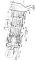
- Figure 1 is a partially sectioned side elevation view of a rotary drum dryer;
- Figure 2 is an enlarged fragmentary perspective view of the flights and dam located in the drum of Figure 1;
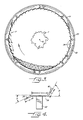
- Figure 3 is an enlarged sectional view taken substantially along the line 3-3 of Figure 1;
- Figure 4 is a fragmentary side elevation view of one of the flights of the present invention; and
- Figure 5 is a view similar to Figure 1 but illustrating a drum dryer of the parallel flow type.
- Referring more particularly to the drawings, Figure 1 schematically illustrates a rotary drum dryer 10 in accordance with one preferred embodiment of the present invention. The dryer 10 comprises an elongate
hollow drum 12 having acylindrical wall 14, and which defines acentral axis 15 which is inclined with respect to the horizontal H so as to define an upper end 16 and alower end 17 of the drum. - The
drum 12 is rotatably mounted on a frame by means ofbearing sleeves 18 and so as to be rotatable about thecentral axis 15. A motor which is shown schematically in Figure 1 at 20 rotates the drum about the central axis in a conventional manner. An aggregate delivery conveyor 21 is positioned adjacent the upper end of the drum for introducing stone aggregate or the like into the interior of drum, and anaggregate outlet duct 22 is positioned at the lower end of the drum. - A plurality of lifting
flights 24 of conventional design are mounted on the inside of the drum and along the major portion of the axial length of the drum for lifting the aggregate and dropping the same through the interior of the dryer as it is rotated. Thus the aggregate which is introduced into the drum via the inlet conveyor 21 is caused to cascade through the interior of the drum, and move toward the outlet duct. - The drum dryer further includes a
burner 26 which is mounted at the lower end of the drum for directing a high temperature flame into the interior of the drum. Theburner 26 is of conventional design, and it includes ablower 27 which charges a mixture of fuel and air into the burner, where it is ignited to produce a flame for heating the interior of the drum. Anexhaust air duct 28 is positioned at the upper end of the drum, for exhausting the heated gases from the drum and so that the heated gas flows through the drum to heat the cascading aggregate. The exhaust air flow may be conveyed through the duct to a conventional filtering baghouse (not shown) and then released to the atmosphere. - The flame F of the burner defines a combustion zone in the drum which surrounds at least a substantial portion of the length of the flame, and in accordance with the present invention, a
dam 30 is mounted to the inside wall of the drum in a coaxially encircling manner adjacent the downstream end of the combustion zone. Thedam 30 comprises a plurality of aligned and interconnected metal plates, and it defines an insidecircumferential edge 31 which is spaced from the wall of the drum. Also, in the illustrated embodiment, all of the plates of thedam 30 include anopening 32 adjacent the inside surface of the wall of the drum, to facilitate cleaning of the aggregate therefrom. - Also a plurality of longitudinally extending
flights 34 are mounted to the inside surface of the wall of the drum and so as to extend upstream from the dam along the length of the combustion zone. Each of thecombustion zone flights 34, when viewed in transverse cross section as seen in Figure 4, comprises a generally planarmedial portion 36 having opposite side edges, a leadingedge portion 38 extending from the leading side edge of the medial portion when viewed in the rotational direction of the drum, and a trailing edge portion 40 extending from the other side edge. Themedial portion 36 when viewed in transverse cross section is generally perpendicular to a radial line extending from thecentral axis 15, and themedial portion 36 is aligned with the adjacent portion of thecircumferential edge 31 of thedam 30 as best seen in Figure 2. Also, the leadingedge portion 38 and the trailing edge portion 40 each have a transverse , dimension which is about one half that of the medial portion, and the leadingedge portion 38 extends downwardly toward the wall of the drum at an angle A of about 30° from the plane of the medial portion, and the trailing edge portion 40 extends upwardly from the plane of the medial portion at an angle B of about 70°. - The
flights 34 are equally spaced about the entire circumference of the inside surface of the wall of the drum, and they are mounted to the drum by means of theposts 42. More particularly, theposts 42 comprise an angled metal member, and three or four of such posts are positioned in a longitudinally spaced apart arrangement along the length of each flight for mounting the flight to the wall of the drum. As best seen in Figure 3, theflights 34 are positioned sufficiently close to each other so that the inside wall of the drum is substantially completely covered in the radial direction. Thus the wall of the drum is substantially completely shielded from the radiant heat of the flame F in the combustion zone. - In a typical installation, the drum has a diameter of about eight feet (2.44m) and a longitudinal length of about forty feet (12.19m). Also, the
combustion zone flights 34 have a longitudinal length of about ten feet (3.05m), and the media portions have a width C (Figure 3) of about six inches (152 mm). The leadingedge portion 38 of each flight has a width D of about three inches (76 mm), and the trailing edge portion 40 of each flight has a width E of about three inches (76 mm). Thedam 30 has a radial height of about six inches (152 mm). - In operation, the aggregate is continuously introduced into the upper end of the rotating drum by the inlet conveyor 21, and the aggregate cascades through the interior of the drum and moves toward the
outlet duct 22 at thelower end 17. Also, with theburner 26 in operation, heated gases flow through the length of the drum in a direction counter to the direction of movement of the aggregate and exhausts through theoutlet duct 28 to the filtering baghouse. - The
dam 30 is located adjacent the downstream end of the combustion zone when viewed in the direction of movement of the aggregate, and it serves to retain the aggregate in the combustion zone and to cause the level of the aggregate to rise so that the flights move through the aggregate which is in the bottom of the drum and collect a portion of the aggregate on their radially inwardly facing surfaces, note Figure 3. As the level of the aggregate in the bottom of the drum is above theflights 34, the aggregate is directly exposed to the radiant heat from the flame. As the flights lift from the aggregate in the bottom of the rotating drum, a portion of the aggregate is retained by the upstanding trailing edge portions 40 of the flights, and this retained aggregate is lifted to a discharge point P, which as seen in Figure 3, is about 150° from the opposite edge of the aggregate layer in the bottom of the drum. Thus the aggregate is exposed to the radiant energy through nearly one-half of the arc of the drum. - It will also be understood that since the
flights 34 extend below the level of the aggregate in the bottom of the drum, and are covered by retained aggregate on their top surfaces along another portion of their circular path of travel, theflights 34 are shielded from exposure to the radiant heat energy for a significant portion of their circular travel. This results in the flights being cooler, which in turn reduces warpage or other deterioration of the flights. Also, it will be understood that the temperature of thedrum wall 14 and the resulting metal deterioration of the wall are also reduced, since more of the radiant heat energy is transferred directly to the aggregate. - In the embodiment of Figure 5 (in which parts corresponding to parts shown in Figure 1 have been given like reference numbers followed by a) the
rotatable drum dryer 10a is similarly mounted for rotation about anaxis 15a which is inclined with respect to the horizontal, with theaggregate inlet conveyor 21a being positioned adjacent the upper end of the dryer and theaggregate outlet duct 22a being positioned adjacent the lower end of the dryer. In this embodiment however, theburner 26a is disposed adjacent the upper end of the drum so that the aggregate moves through the drum in a direction parallel to the direction of gas flow through the drum. Also, this embodiment incorporates essentially the same lifting flights 24a,dam 30a, and combustion zone flights 34a, as in the embodiment of Figures 1-4, and the operation of thedam 30a and flights 34a is essentially the same as that described in the initial embodiment. - In the drawings and specification there has been set forth two preferred embodiments of the invention, and although specific terms are employed, they are used in a generic and descriptive sense only and not for purposes of limitation.
Claims (16)
- A rotary drum dryer (10) comprising:a hollow drum (12, 12a) having a cylindrical wall (14, 14a) and which is mounted for rotation about a central axis (15);means (20, 20a) for rotating said drum about said central axis (15, 15a);aggregate inlet means (21, 21a) for introducing aggregate into the interior of said drum and aggregate outlet means (22, 22a) for withdrawing the aggregate from the interior of said drum, and so as to define a downstream direction when viewed in the direction of the movement of the aggregate from the inlet means (21, 21a) toward the outlet means (22, 22a) and an opposite upstream direction;heating means comprising a burner (26, 26a) positioned adjacent an end of said drum (12, 12a) for introducing air and a high temperature flame into the interior of said drum, and so as to define a combustion zone in said drum which surrounds said flame;a dam (30, 30a) coaxially encircling the inside of said wall (14, 14a) of said drum (12, 12a) and defining an inside circumferential edge (31) which is spaced from said wall of said drum; anda plurality of longitudinally extending flights (34, 34a) mounted to the inside surface of wall and said flights being spaced about substantially the entire circumference of the inside surface of said wall of said drum and extending upstream of said dam,characterised in that (i) said dam (30, 30a) is located adjacent the downstream end of said combustion zone, (ii) said flights (34, 34a) extend along the length of said combustion zone, (iii) each of said flights, when viewed in transverse cross section, comprises a medial portion (36) which is generally perpendicular to a radial line extending from said central axis (15, 15a) and the trailing edge portion (40) which extends inclined away from said wall (14,14a) from said medial portion (36), and (iv) said dam is adapted to retain and raise the level of the aggregate flowing through said combustion zone so that the flights pass through the aggregate in the bottom of the drum in the combustion zone and collect a portion of the aggregate on their radially inwardly facing surfaces and carry the collected aggregate to an elevated discharge point (P).
- A rotary drum drier as claimed in claim 1, wherein said medial portion (36) of each of said flights, when viewed in transverse cross-section, is generally parallel to an adjacent portion of said inside circumferential edge (31) of said dam.
- A rotary drum dryer as claimed in claim 2, wherein said medial portion (36) of said flights, when viewed in transverse cross-section, lies at a level which generally corresponds to the level of the adjacent portion of said inside circumferential edge (31) of said dam.
- A rotary drum dryer as claimed in claim 1, 2 or 3, wherein said medial portion (36) of each of said flights (34, 34a) is generally planar and defines a plane which is substantially perpendicular to a radial line extending from said central axis.
- A rotary drum drier as claimed in anyone of the preceding claims, wherein said trailing edge portion (40) of each of said flights extends from said plane of said medial portion (36) at an angle of about 70°.
- A rotary drum dryer as claimed in anyone of the preceding claims, wherein each of said flights further comprises a leading edge portion (38) which is positioned on the side of said medial portion (36) opposite said trailing edge portion (40), and wherein said leading edge portion (38) is inclined toward the wall (14, 14a) of said drum.
- A rotary drum drier as claimed in claim 6 when appended to claim 5, wherein said leading edge portion (38) extends from said plane of said medial portion (36) at an angle of about 30 degrees.
- A rotary drum dryer as claimed in claim 6 or 7, wherein said leading edge portion (38) and said trailing edge portion (40) of each flight (34, 34a) each have a transverse dimension which is about one half that of said medial portion (36).
- A rotary drum dryer as claimed in any one of the preceding claims, wherein said flights (34, 34a) are equally spaced about the entire circumference of the inside surface of said cylindrical wall of said drum.
- A rotary drum dryer as claimed in claim 9, wherein said flights (34, 34a) are positioned sufficiently close to each other that the inside surface of said cylindrical wall is substantially completely covered in the radial direction.
- A rotary drum dryer as claimed in any one of the preceding claims wherein said flights (34, 34a) are supported in spaced relation from the inside surface of said wall (14, 14a) of said drum by a plurality of longitudinally spaced apart posts (42).
- A rotary drum dryer as claimed in any one of the preceding claims, wherein said dam (30, 30a) comprises a plurality of aligned and interconnected plates, and a plurality of openings (32) extend through at least some of said plates immediately adjacent the inside surface of said wall (14, 14a) of said drum to facilitate cleaning of the aggregate therefrom.
- A rotary drum dryer as claimed in any one of the preceding claims further comprising lifting flight means (24) mounted to that portion of said inside surface of said wall (14, 14a) of said drum which is outside of said combustion zone for lifting and cascading the aggregate as it flows in the downstream direction through the interior of the drum on rotation thereof.
- A rotary drum dryer as claimed in any one of the preceding claims, further comprising means (18, 18a) mounting said drum (12, 12a) for rotation about said central axis (15, 15a) and with said central axis being inclined with respect to the horizontal so as to define an upper end and a lower end of said drum.
- A rotary drum dryer as claimed in claim 14, wherein said heating means is disposed adjacent said lower end of said drum and exhaust duct means (28) is positioned adjacent the upper end of said drum so that the aggregate moving through said drum in the downstream direction moves counter to the direction of gas flow through said drum.
- A rotary drum dryer as claimed in claim 14, wherein said heating means is disposed adjacent said upper end of said drum and exhaust duct means (28a) is positioned adjacent said lower end of said drum so that the aggregate moving through said drum in the downstream direction moves parallel to the direction of gas flow through said drum.
Applications Claiming Priority (3)
| Application Number | Priority Date | Filing Date | Title |
|---|---|---|---|
| US07/769,963 US5203693A (en) | 1991-10-01 | 1991-10-01 | Rotary drum dryer having internal flights |
| US769963 | 1991-10-01 | ||
| PCT/US1992/008373 WO1993007431A1 (en) | 1991-10-01 | 1992-09-30 | Rotary drum dryer having internal flights |
Publications (2)
| Publication Number | Publication Date |
|---|---|
| EP0612395A1 EP0612395A1 (en) | 1994-08-31 |
| EP0612395B1 true EP0612395B1 (en) | 1997-04-09 |
Family
ID=25087049
Family Applications (1)
| Application Number | Title | Priority Date | Filing Date |
|---|---|---|---|
| EP92922001A Expired - Lifetime EP0612395B1 (en) | 1991-10-01 | 1992-09-30 | Rotary drum dryer having internal flights |
Country Status (5)
| Country | Link |
|---|---|
| US (1) | US5203693A (en) |
| EP (1) | EP0612395B1 (en) |
| AU (1) | AU2866692A (en) |
| DE (1) | DE69218962T2 (en) |
| WO (1) | WO1993007431A1 (en) |
Families Citing this family (27)
| Publication number | Priority date | Publication date | Assignee | Title |
|---|---|---|---|---|
| US5361708A (en) * | 1993-02-09 | 1994-11-08 | Barnes Alva D | Apparatus and method for pasteurizing and drying sludge |
| US5372458A (en) * | 1993-07-15 | 1994-12-13 | Flemmer; Henry | System for treating drilling mud containing potassium chloride (KCl) for disposal |
| US5522158A (en) * | 1994-03-07 | 1996-06-04 | Astec Industries, Inc. | Dryer drum coater having recirculation chamber for VOC/NOX reduction |
| US5480226A (en) * | 1994-05-09 | 1996-01-02 | Astec Industries, Inc. | Rotary drum dryer having aggregate cooled shielding flights and method for the utilization thereof |
| US5772317A (en) * | 1996-08-27 | 1998-06-30 | Gencor Industries, Inc. | Counterflow drum mixer for making asphaltic concrete and methods of operation |
| US5904904A (en) * | 1996-10-31 | 1999-05-18 | Astec Industries, Inc. | Treatment of contaminated particulate material by low-temperature thermal desorption with indirect heating |
| US5975752A (en) * | 1998-02-25 | 1999-11-02 | Conoco Inc. | Fabricated steel lifter for rotary kiln |
| US5997289A (en) * | 1998-05-01 | 1999-12-07 | Harper International Corp. | Rotary calciner with mixing flights |
| US6969249B2 (en) * | 2003-05-02 | 2005-11-29 | Hauck Manufacturing, Inc. | Aggregate dryer burner with compressed air oil atomizer |
| US7163392B2 (en) * | 2003-09-05 | 2007-01-16 | Feese James J | Three stage low NOx burner and method |
| US20070070801A1 (en) * | 2005-09-23 | 2007-03-29 | Cedarapids, Inc. | Pre-combustion mix drum |
| US7927413B2 (en) | 2007-04-17 | 2011-04-19 | Astec, Inc. | Method and apparatus for making asphalt concrete using foamed asphalt cement |
| ITVE20070080A1 (en) * | 2007-10-25 | 2009-04-26 | Piovan Spa | INFRARED DEHUMIDIFIER |
| BE1017939A3 (en) † | 2008-02-27 | 2009-12-01 | Majast Bvba | DEVICE FOR DRYING A WATER-MIXING MIXTURE. |
| US8220982B2 (en) | 2008-07-22 | 2012-07-17 | Terex Usa, Llc | Energy efficient asphalt plant |
| US8920210B2 (en) * | 2009-06-18 | 2014-12-30 | Ronald C. Benson | System and method for drying grit used for abrasive blasting |
| US9382672B2 (en) * | 2010-12-06 | 2016-07-05 | Astec, Inc. | Apparatus and method for dryer performance optimization system |
| US8863404B1 (en) * | 2010-12-06 | 2014-10-21 | Astec, Inc. | Apparatus and method for dryer performance optimization system |
| FR2986016B1 (en) * | 2012-01-25 | 2014-03-21 | Argumat | DEVICE AND METHOD FOR MANUFACTURING COATED PRODUCTS, FOR EXAMPLE OF BITUMINOUS COATED PRODUCTS, WITH PROTECTIVE PLATES |
| CN102997629B (en) * | 2012-12-17 | 2014-07-02 | 湖南平和科技有限公司 | Biomass gasification rotating cylinder drying equipment |
| JP2017020309A (en) * | 2015-07-14 | 2017-01-26 | 日工株式会社 | Drier of asphalt plant |
| CO2017011592A1 (en) * | 2017-11-14 | 2018-03-09 | Qmax Solutions Colombia | Device and method of dehydration of fluids and cuts |
| KR102806692B1 (en) * | 2018-08-07 | 2025-05-13 | 노벨리스 인크. | Adjustable kiln flight for rotary kiln decoater and associated method |
| KR102466831B1 (en) | 2020-12-15 | 2022-11-14 | 고등기술연구원연구조합 | Rotary kiln and driving method thereof |
| EP4053483A1 (en) | 2021-03-05 | 2022-09-07 | S.A. Lhoist Recherche et Développement | Rotary kiln and method for firing carbonaceous material, in particular limestone or dolomite |
| EP4053485A1 (en) * | 2021-03-05 | 2022-09-07 | S.A. Lhoist Recherche et Développement | Rotary kiln and method for firing carbonaceous material, in particular limestone or dolomite |
| EP4053484A1 (en) | 2021-03-05 | 2022-09-07 | S.A. Lhoist Recherche et Développement | Rotary kiln and method for firing carbonaceous material, in particular limestone or dolomite |
Family Cites Families (26)
| Publication number | Priority date | Publication date | Assignee | Title |
|---|---|---|---|---|
| BE565990A (en) * | ||||
| DE501831C (en) * | 1930-07-05 | Adam Helmer Pehrson | Rotatable drying drum with hot gas supply ducts running along the length of the drum shell | |
| DE530272C (en) * | 1929-03-28 | 1931-07-25 | Elsbeth Verw Zarniko Geb Witti | Trickle wheels for drying, cooling, ventilation and mixing |
| US2841883A (en) * | 1955-11-10 | 1958-07-08 | Link Belt Co | Apparatus for drying and cooling |
| US2939693A (en) * | 1956-08-06 | 1960-06-07 | Southern Lightweight Aggregate | Rotary kiln |
| GB905659A (en) * | 1957-10-24 | 1962-09-12 | Dunford & Elliott Process Engi | Improvements in a method and apparatus for the exchange of heat between gases and particulate materials |
| DE2255069B2 (en) * | 1972-11-10 | 1977-03-03 | Polysius Ag, 4723 Neubeckum | DRUM FOR THERMAL TREATMENT OF WEARING GOODS |
| US3798789A (en) * | 1973-02-28 | 1974-03-26 | S Thompson | Flighting for dehydrator drum and method |
| US3950861A (en) * | 1974-11-29 | 1976-04-20 | Stearns-Roger Corporation | Rotary dryer for stringy material |
| DE2717583C3 (en) * | 1977-04-20 | 1980-09-18 | Olin Corp., New Haven, Conn. (V.St.A.) | Drum dryer |
| FR2441682A1 (en) * | 1978-11-17 | 1980-06-13 | Creusot Loire | DEVICE FOR THE PREPARATION OF BITUMINOUS COATED PRODUCTS FOR ROAD COVERINGS |
| US4190370A (en) * | 1978-11-24 | 1980-02-26 | Astec Industries, Inc. | Asphalt plant with improved temperature control system |
| US4332478A (en) * | 1979-05-16 | 1982-06-01 | Barber-Greene Company | Method and apparatus for reducing smoke emissions in an asphalt drum mixer |
| FR2473578B1 (en) * | 1980-01-11 | 1986-03-21 | Creusot Loire | |
| US4300837A (en) * | 1980-03-07 | 1981-11-17 | Creusot-Loire | Device for the preparation of coated bituminous products for road surfacing |
| US4298287A (en) * | 1980-04-25 | 1981-11-03 | The Mccarter Corporation | Center draft asphaltic concrete drum mixer |
| US4480922A (en) * | 1980-08-22 | 1984-11-06 | Mendenhall Robert Lamar | Recycling apparatus for particulate asphaltic concrete |
| US4422848A (en) * | 1982-01-29 | 1983-12-27 | Iowa Manufacturing Company Of Cedar Rapids, Iowa | Heat shields for drum aggregate driers and asphaltic drum mixers |
| FR2582329B1 (en) * | 1985-05-24 | 1987-08-14 | Ermont Sa | PROCESS AND DEVICE FOR PRODUCING BITUMINOUS COATED PRODUCTS FROM AGGREGATES CONTAINING A HIGH QUANTITY OF FINES. |
| US4797002A (en) * | 1986-06-23 | 1989-01-10 | Standard Havens, Inc. | Apparatus for mixing asphalt compositions |
| US4787938B3 (en) * | 1986-06-30 | 1999-11-30 | Standard Havens | Countercurrent drum mixer asphalt plant |
| US4802139A (en) * | 1987-08-21 | 1989-01-31 | Taisei Road Construction Co., Ltd. | Apparatus for producing a heated reproduction asphalt mixture |
| US4867572A (en) * | 1987-09-08 | 1989-09-19 | Astec Industries, Inc. | Asphalt plant with fixed sleeve mixer |
| FR2645556B1 (en) * | 1989-04-05 | 1991-07-19 | Ermont Cm | DRYER AND DRYER FOR THE PREPARATION OF BITUMINOUS COATED PRODUCTS COMPRISING AN IMPROVED BURNER |
| US5052810A (en) * | 1990-02-16 | 1991-10-01 | Astec Industries, Inc. | Asphalt drum mixer with bypass temperature control |
| US5083382A (en) * | 1990-12-11 | 1992-01-28 | Gencor Industries Inc. | Adjustable flights with dams for rotary dryers |
-
1991
- 1991-10-01 US US07/769,963 patent/US5203693A/en not_active Expired - Lifetime
-
1992
- 1992-09-30 WO PCT/US1992/008373 patent/WO1993007431A1/en not_active Ceased
- 1992-09-30 AU AU28666/92A patent/AU2866692A/en not_active Abandoned
- 1992-09-30 EP EP92922001A patent/EP0612395B1/en not_active Expired - Lifetime
- 1992-09-30 DE DE69218962T patent/DE69218962T2/en not_active Expired - Fee Related
Also Published As
| Publication number | Publication date |
|---|---|
| WO1993007431A1 (en) | 1993-04-15 |
| DE69218962T2 (en) | 1997-10-16 |
| EP0612395A1 (en) | 1994-08-31 |
| US5203693A (en) | 1993-04-20 |
| AU2866692A (en) | 1993-05-03 |
| DE69218962D1 (en) | 1997-05-15 |
Similar Documents
| Publication | Publication Date | Title |
|---|---|---|
| US5203693A (en) | Rotary drum dryer having internal flights | |
| JP2896531B2 (en) | Drum dryer with crushed stone cooling shield member | |
| US5558432A (en) | Drum mixer having a combined heating/mixing zone with aggregate entry at both ends | |
| US4867572A (en) | Asphalt plant with fixed sleeve mixer | |
| US5364182A (en) | Counter-flow asphalt plant with multi-stage combustion zone overlapping the mixing zone | |
| US7044630B1 (en) | Counter-flow asphalt plant method | |
| US5664881A (en) | Counter-flow asphalt plant with multi-stage combustion zone overlapping the mixing zone | |
| US5052810A (en) | Asphalt drum mixer with bypass temperature control | |
| US5261738A (en) | Asphalt drum mixer with bypass for controlling the temperature of the exhaust gas | |
| US4371375A (en) | Apparatus and process for drying sawdust | |
| AU713149B2 (en) | Counterflow drum mixer for making asphaltic concrete and methods of operation | |
| JPH02112506A (en) | Apparatus for manufacturing a coating product of bitumen with use of a stationary mixer | |
| US5380084A (en) | Asphalt drum mixer with self-scouring drum | |
| RU2536068C2 (en) | Rotary drum-type drier for plants for production of bitumen macadam with application of reusable materials | |
| US5294197A (en) | Asphalt manufacturing assembly | |
| EP0678131B1 (en) | Asphalt drum mixer with temperature control | |
| JPH0363302A (en) | Drying/coating drum with improved burner for manufacturing bitumen coated product | |
| US5052809A (en) | Rotary drier | |
| US3076270A (en) | Sand or fines filtering device for dryers | |
| US2746170A (en) | Rotary dryer | |
| CA1065133A (en) | Drying apparatus | |
| GB2506440A (en) | Apparatus for drying particulate material | |
| EP0562234B1 (en) | Drum mixer-drier for the continuous preparation of bituminous mixes with recycling of reclaimed materials | |
| KR100485823B1 (en) | apparatus for drying aggregate | |
| KR200304867Y1 (en) | apparatus for drying aggregate |
Legal Events
| Date | Code | Title | Description |
|---|---|---|---|
| PUAI | Public reference made under article 153(3) epc to a published international application that has entered the european phase |
Free format text: ORIGINAL CODE: 0009012 |
|
| 17P | Request for examination filed |
Effective date: 19940701 |
|
| AK | Designated contracting states |
Kind code of ref document: A1 Designated state(s): CH DE ES FR GB IT LI NL |
|
| 17Q | First examination report despatched |
Effective date: 19950613 |
|
| GRAG | Despatch of communication of intention to grant |
Free format text: ORIGINAL CODE: EPIDOS AGRA |
|
| GRAH | Despatch of communication of intention to grant a patent |
Free format text: ORIGINAL CODE: EPIDOS IGRA |
|
| GRAH | Despatch of communication of intention to grant a patent |
Free format text: ORIGINAL CODE: EPIDOS IGRA |
|
| GRAA | (expected) grant |
Free format text: ORIGINAL CODE: 0009210 |
|
| AK | Designated contracting states |
Kind code of ref document: B1 Designated state(s): CH DE ES FR GB IT LI NL |
|
| PG25 | Lapsed in a contracting state [announced via postgrant information from national office to epo] |
Ref country code: LI Effective date: 19970409 Ref country code: IT Free format text: LAPSE BECAUSE OF FAILURE TO SUBMIT A TRANSLATION OF THE DESCRIPTION OR TO PAY THE FEE WITHIN THE PRE;WARNING: LAPSES OF ITALIAN PATENTS WITH EFFECTIVE DATE BEFORE 2007 MAY HAVE OCCURRED AT ANY TIME BEFORE 2007. THE CORRECT EFFECTIVE DATE MAY BE DIFFERENT FROM THE ONE RECORDED.SCRIBED TIME-LIMIT Effective date: 19970409 Ref country code: FR Effective date: 19970409 Ref country code: ES Free format text: THE PATENT HAS BEEN ANNULLED BY A DECISION OF A NATIONAL AUTHORITY Effective date: 19970409 Ref country code: CH Effective date: 19970409 |
|
| REG | Reference to a national code |
Ref country code: CH Ref legal event code: EP |
|
| REF | Corresponds to: |
Ref document number: 69218962 Country of ref document: DE Date of ref document: 19970515 |
|
| EN | Fr: translation not filed | ||
| REG | Reference to a national code |
Ref country code: CH Ref legal event code: PL |
|
| PLBE | No opposition filed within time limit |
Free format text: ORIGINAL CODE: 0009261 |
|
| STAA | Information on the status of an ep patent application or granted ep patent |
Free format text: STATUS: NO OPPOSITION FILED WITHIN TIME LIMIT |
|
| 26N | No opposition filed | ||
| PGFP | Annual fee paid to national office [announced via postgrant information from national office to epo] |
Ref country code: GB Payment date: 19990929 Year of fee payment: 8 |
|
| PGFP | Annual fee paid to national office [announced via postgrant information from national office to epo] |
Ref country code: NL Payment date: 19990930 Year of fee payment: 8 |
|
| PGFP | Annual fee paid to national office [announced via postgrant information from national office to epo] |
Ref country code: DE Payment date: 19991001 Year of fee payment: 8 |
|
| PG25 | Lapsed in a contracting state [announced via postgrant information from national office to epo] |
Ref country code: GB Free format text: LAPSE BECAUSE OF NON-PAYMENT OF DUE FEES Effective date: 20000930 |
|
| PG25 | Lapsed in a contracting state [announced via postgrant information from national office to epo] |
Ref country code: NL Free format text: LAPSE BECAUSE OF NON-PAYMENT OF DUE FEES Effective date: 20010401 |
|
| GBPC | Gb: european patent ceased through non-payment of renewal fee |
Effective date: 20000930 |
|
| NLV4 | Nl: lapsed or anulled due to non-payment of the annual fee |
Effective date: 20010401 |
|
| PG25 | Lapsed in a contracting state [announced via postgrant information from national office to epo] |
Ref country code: DE Free format text: LAPSE BECAUSE OF NON-PAYMENT OF DUE FEES Effective date: 20010601 |