EP0612287B1 - A cap for writing and marking instruments - Google Patents
A cap for writing and marking instruments Download PDFInfo
- Publication number
- EP0612287B1 EP0612287B1 EP92924438A EP92924438A EP0612287B1 EP 0612287 B1 EP0612287 B1 EP 0612287B1 EP 92924438 A EP92924438 A EP 92924438A EP 92924438 A EP92924438 A EP 92924438A EP 0612287 B1 EP0612287 B1 EP 0612287B1
- Authority
- EP
- European Patent Office
- Prior art keywords
- tubular member
- removable cap
- land portion
- cap
- frusto
- Prior art date
- Legal status (The legal status is an assumption and is not a legal conclusion. Google has not performed a legal analysis and makes no representation as to the accuracy of the status listed.)
- Expired - Lifetime
Links
Images



Classifications
-
- B—PERFORMING OPERATIONS; TRANSPORTING
- B43—WRITING OR DRAWING IMPLEMENTS; BUREAU ACCESSORIES
- B43K—IMPLEMENTS FOR WRITING OR DRAWING
- B43K23/00—Holders or connectors for writing implements; Means for protecting the writing-points
- B43K23/08—Protecting means, e.g. caps
- B43K23/12—Protecting means, e.g. caps for pens
- B43K23/122—Protecting means, e.g. caps for pens with means for preventing choking
- B43K23/124—Protecting means, e.g. caps for pens with means for preventing choking comprising an air passage
Definitions
- the present invention relates to removable protective caps for writing implements, and in particular, to a removable cap having a passageway to permit air to flow into the interior of the cap and circulate to dry residual ink at the writing point.
- Removable caps for writing implements are typically configured to enclose the writing portion of the implement to protect the functional components therein.
- a conventional removable cap usually includes a hollow body member having an opening at one end to receive the implement and being closed at the other end to enclose the writing portion of the instrument within the body member.
- removable caps are effective in protecting the functional components of an implement, these caps present several disadvantages.
- the conventional removable cap effectively seals the writing point, such sealing thereby preventing the residual ink at the writing point from drying after use. Consequently, seepage of ink from the point commonly occurs.
- some known removable caps have been provided with apertures which permit air to flow through the interiors of the caps when the caps are secured on the implements. Examples of such configurations are illustrated in WO 89/11978 and U.S. Patent Nos. 5,000,604, 5,000,603, and 4,915,529.
- WO 89/11978 describes a cap for writing instruments having a double end wall and a circuitous air channel which perforates the front face of the implement. While there is a circuitous path for air flow, the double end wall provides a complex construction requiring close tolerances during construction to prevent obstruction of the vent openings.
- US 5,000,603 and US 5,000,604 each describe a safety cap having a cylindrical outer body and a corresponding cylindrical inner cap which is attached to the outer body for sealing the tip of a pen or marker
- List ('529) describes a cap body having an axial passageway which is disposed within the cap body and runs parallel to a sealing channel which covers the pen or writing instrument tip.
- GB 2,233,607 discloses a writing instrument cap (5) comprising an inner cap (6) having an opening only at the front end thereof for completely enclosing the pen point (3), and an outer cap (16) provided with air holes (7) to prevent suffocation if the cap (5) is accidently swallowed.
- the cap (16) is closed with a flat base plate (9) at a rear end thereof.
- the aforementioned devices provide a passage for air to flow through the interior of the cap, these devices present a number of disadvantages. As made apparent by the foregoing descriptions, they are relatively structurally complex and rely on strategically positioned apertures and/or interconnected spaces to establish the air passageway. Furthermore, many do not provide for circulation of air about the writing tip when the cap is positioned on the writing instrument.
- the present invention provides a protective removable cap for a writing implement that effectively engages and protects the writing portion of an implement, while allowing air to circulate about the point to dry residual ink at the writing point.
- the cap is also configured to allow for circulation of air while preventing contact of the writing point of the implement with the closed end of the cap.
- a vented removable cap for receiving a writing implement comprising a hollow tubular member having an opening at a first end and a closing wall at a second end.
- the closing wall comprises a generally circular interior land portion and a plurality of radial rib members which define arcuately-shaped openings surrounding the land portion.
- the radial rib members extend from the circular land portion to an inner peripheral surface of the closing wall.
- the closing wall may also include an annular surface extending from the tubular member in a concentric manner, extending from the second end of the tubular member along a longitudinal axis of the tubular member.
- a beveled surface may also be provided, which extends from the annular surface and is also concentric with the tubular member.
- the circular land portion is thereby secured to the beveled surface by the radial rib members.
- the annular surface and the beveled surface provide additional spacing at the second end of the tubular member to accommodate the tip of the writing instrument and to facilitate circulation of air about the tip when the cap is positioned on the writing instrument.
- the tubular member of the removable cap also includes a plurality of axially extending partial ribs on the inner peripheral surface thereof adjacent its proximal end.
- An inner circumferential rib may also be provided and disposed at a position intermediate the ends of the tubular member.
- the axially extending partial ribs and the circumferential rib are adapted to frictionally engage the outer peripheral surface of the writing implement to limit insertion of the writing instrument into the removable cap to maintain space at the second end of the cap to allow for air circulation.
- FIG. 1 illustrates a protective removable cap 10 in accordance with the present invention.
- Removable cap 10 is configured to receive and enclose the writing portion of a writing implement, as shown in phantom in FIG. 2, to allow for the circulation of air about the tip of the writing instrument to prevent seepage of ink and subsequent blotting and clogging of the tip, when the cap is positioned on the writing instrument.
- the cap protects the components of the writing instrument therein and prevents the user from engaging the sharp point of the implement when not in use.
- removable cap 10 is integrally formed as a single piece unit by conventional injection molding techniques. Such techniques are capable of manufacturing removable caps cost effectively and in great volume.
- removable cap 10 comprises a tubular member 12 having an opening 14 at a first end, a longitudinally circular passageway through which the body of an implement may pass, and closing wall 16 at a second end.
- Tubular member 12 may taper in diameter towards closing wall 16, such configuration corresponding to the tapering of a writing implement towards its writing point.
- tubular member 12 is not limited to this tapering configuration and may in the alternative be generally cylindrically shaped.
- Tubular member 12 may also include a pocket clip 15 which is integrally molded with the tubular member, or tubular member 12 may not be provided with such a clip, as shown in FIG. 10.
- FIG. 4A illustrates an axial view of the closing wall 16 of the cap
- FIG. 5 illustrates an enlarged partial perspective view of the closing wall.
- Closing wall 16 is integrally formed with tubular member 12 and includes an annular surface 18 which extends from the second end of tubular member 12 in a longitudinal direction.
- the diameter of annular surface 18 is uniform throughout its length and is slightly smaller than the diameter of the tubular member at its second end.
- a beveled surface 20 may also be provided which extends from annular surface 18 and tapers in diameter as shown.
- Beveled surface 20 provides closing wall 16 a dome-like appearance as best illustrated in FIG. 5.
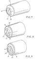
- closing wall 16 may be formed without annular surface 18 as shown in FIG. 7, such that in this embodiment beveled surface 20 extends directly from the second end of tubular member 12.
- closing wall 16 also includes a generally circular land portion 22 and three rib members which extend radially from circular land portion 22 and engage tubular member 12 at the inner peripheral surface of closing wall 16, or at the inner surface of annular surface 18.
- Rib members 26 form three arcuately shaped apertures 24 which form an overall circular pattern around the land portion.
- Apertures 24 provide a passageway wherein the interior of the removable cap is in direct communication with air on the exterior side of closing wall 16.
- air can freely flow into the interior of cap 10 and circulate about the writing point of the implement to dry residual ink and prevent undesirable blotting and clogging of the writing point.
- Apertures 24 are of sufficient size to provide an adequate flow of air. It is to be noted that the number of apertures 24 and rib portions 26 is not limited to three and land portion 22 may assume any shape.
- annular surface 18 extends away from tubular member 12 in the longitudinal direction and beveled surface 20 similarly tapers away from annular surface 18, the combination of each effecting a raised configuration of closing wall 16, whereby circular land portion 22 is distally displaced relative to the second end of tubular member 12 but within the plane defined by beveled surface 20.
- This displacement enables the removable cap to receive and accommodate the writing point of an implement without experiencing contact between the point and the circular land portion even in situations wherein the implement is inserted too deeply within tubular member 12 and the point of the implement protrudes past the end of tubular member 12.
- damage occurring to the writing point due to contact with the land portion and closing wall is avoided.
- land portion 22 and the end of beveled surface 20 are at the same position along the longitudinal axis defined by tubular member 12.
- land portion 22 is further displaced from the end of beveled surface 20, such as shown in FIG. 8.
- Land portion 22 may extend beyond the plane of the end of beveled surface 20 to provide additional space for the writing point of the implement. This feature is made possible by increasing the length of ribs 26 and/or adjusting the angles of the ribs relative to the longitudinal axis defined by tubular member 12. It is also within the scope of the present invention for land portion 22 to be displaced towards the open end of tubular member 12 in relation to beveled surface 20 as shown in FIG. 9.
- land portion 22 is disposed within the interior of closing wall 16, but still remains disposed beyond the end of tubular member 12.
- Receiving section 28 is generally cylindrically- shaped and is adapted to receive a writing implement of similar configuration.
- the inner diameter of end section 28 remains constant throughout the length of the end section. It is also preferable that the inner diameter at opening 14 and receiving section 28 be slightly greater than the diameter of the implement to be inserted. As will be appreciated from the following description, such dimensioning will facilitate the insertion and retention of the writing implement within removable cap 10.
- a plurality of axially extending partial ribs 30 are provided on the inner surface of end section 28 adjacent opening 14. Ribs 30 are spaced equidistantly along the inner peripheral surface of receiving section 28 and are slightly raised from the inner surface of the receiving section.
- a circumferential rib 32 is also provided and disposed between receiving section 28 and closing wall 16. Circumferential rib 32 is slightly raised above the inner surface of tubular member 12 and possesses a diameter which is preferably substantially equal to or less than the peripheral diameter of the implement portion it will engage.
- the combination of partial ribs 30 and circumferential rib 32 forms a sufficient frictional engagement with the peripheral surface of the implement to effectively limit the entry of the instrument and secure the removable cap to the implement, to prevent the implement from being inserted too deeply within the cap.
- the diameter of circumferential rib 32 may be smaller than the effective diameter of partial ribs 30 to correspond to the tapering writing portion of the implement.
- the protective cap of the present invention overcomes the disadvantages of the prior art by providing a simple, inexpensive one-piece protective removable cap that effectively engages a writing implement while also providing an adequate and relatively simple means to allow air to flow about the tip of the writing implement within the interior of the cap.
- the arcuately shaped openings provide direct axial communication with the interior of the protective cap and may be integrally formed with the cap during the injection molding process.
- the raised configuration of the closing wall provides sufficient clearance for the writing point of the implement to avoid undesirable contact between the point and the closing wall of the cap.
Landscapes
- Pens And Brushes (AREA)
- Coating Apparatus (AREA)
- Mechanical Pencils And Projecting And Retracting Systems Therefor, And Multi-System Writing Instruments (AREA)
Abstract
Description
Claims (9)
- A removable cap (10) for receiving a writing implement, comprising:a hollow tubular member (12) defining a longitudinal axis and having first and second ends, said first end defining an opening (14) for receiving the implement; anda closing wall (16) integrally formed at said second end of said tubular member (12), said closing wall (16) comprising:an interior land portion (22); anda plurality of radially directed rib members (26) extending from said land portion (22), said rib members (26) defining a plurality of openings (24) surrounding said land portion (22);
characterized in thatsaid land portion (22) is displaced with respect to said longitudinal axis at a position beyond said second end of said tubular member (12); anda frusto-conical surface (20) is in concentric arrangement with said longitudinal axis defined by said tubular member (12), said frusto-conical surface (20) having first and second ends, said first end of said frusto-conical surface (20) being connected to said second end of said tubular member (12),(i) said land portion (22) and said second end of said frusto-conical surface (20) being at substantially the same position with respect to said longitudinal axis, or(ii) said second end of said frusto-conical surface (20) being disposed at a position beyond said land portion (22) with respect to said longitudinal axis, or(iii) said land portion (22) being disposed at a position beyond said second end of said frusto-conical portion (20) with respect to said longitudinal axis, andsaid rib members (26) radially extend from said land portion (22) to said frusto-conical surface (20) and together with openings (24) define a plurality of direct axial passageways through said closing wall (16) for air to flow from the exterior side of said closing wall (16) to the interior of said removable cap (10) in an unrestricted manner. - The removable cap (10) of Claim 1, wherein said interior land portion (22) is generally circular.
- The removable cap of Claims 1 or 2, wherein said interior land portion (22) comprises a generally planar outer or upper surface.
- The removable cap (10) of any of Claims 1-3, wherein said tubular member (12) also includes at least two axially extending partial ribs (30) and one circumferential rib (32) on an inner peripheral surface thereof, said axial ribs (30) and said circumferential rib (32) adapted to cooperatively frictionally engage an outer peripheral surface of the writing implement.
- The removable cap (10) of any of Claims 1-4, wherein said openings (24) are arcuately-shaped.
- The removable cap (10) of any of Claims 1-5, additionally comprisingan annular member (18) connected to said second end of said tubular member (12) and in concentric arrangement with respect to said longitudinal axis defined by said tubular member (12), with said first end of said frusto-conical surface (20) connected to said annular member (18).
- The removable cap (10) of Claim 6, wherein said annular member (18) is monolithically formed with said tubular member.
- The removable cap (10) of any of Claims 1-7 comprising three of said radially-directed rib members (26) defining three of said openings (24).
- The removable cap (10) of any of Claims 1-8, wherein said rib members (26) each have at least one upper substantially planar surface oriented at an acute angle relative to said longitudinal axis.
Applications Claiming Priority (3)
| Application Number | Priority Date | Filing Date | Title |
|---|---|---|---|
| US07/791,895 US5230578A (en) | 1991-11-13 | 1991-11-13 | Cap for writing and marking instruments |
| US791895 | 1991-11-13 | ||
| PCT/US1992/009814 WO1993009961A1 (en) | 1991-11-13 | 1992-11-12 | A cap for writing and marking instruments |
Publications (3)
| Publication Number | Publication Date |
|---|---|
| EP0612287A1 EP0612287A1 (en) | 1994-08-31 |
| EP0612287A4 EP0612287A4 (en) | 1995-07-05 |
| EP0612287B1 true EP0612287B1 (en) | 1998-10-21 |
Family
ID=25155123
Family Applications (1)
| Application Number | Title | Priority Date | Filing Date |
|---|---|---|---|
| EP92924438A Expired - Lifetime EP0612287B1 (en) | 1991-11-13 | 1992-11-12 | A cap for writing and marking instruments |
Country Status (8)
| Country | Link |
|---|---|
| US (2) | US5230578A (en) |
| EP (1) | EP0612287B1 (en) |
| AT (1) | ATE172411T1 (en) |
| CA (1) | CA2121511C (en) |
| DE (1) | DE69227378T2 (en) |
| DK (1) | DK0612287T3 (en) |
| ES (1) | ES2121873T3 (en) |
| WO (1) | WO1993009961A1 (en) |
Families Citing this family (38)
| Publication number | Priority date | Publication date | Assignee | Title |
|---|---|---|---|---|
| JP2906391B2 (en) * | 1994-10-03 | 1999-06-21 | ゼブラ株式会社 | Writing instrument cap |
| US5590971A (en) * | 1995-06-26 | 1997-01-07 | Pentech International Inc. | Marking pen and cap |
| USD404764S (en) * | 1998-03-26 | 1999-01-26 | Bic Corporation | Writing instrument |
| US6164855A (en) * | 1998-03-26 | 2000-12-26 | Bic Corporation | Writing instrument with finger gripping device |
| US6161975A (en) * | 1999-05-13 | 2000-12-19 | Ek Success, Ltd. | Marker assembly |
| USD418540S (en) * | 1999-07-01 | 2000-01-04 | Robb Karl A | Pen cap stylus |
| USD443301S1 (en) | 2001-01-02 | 2001-06-05 | Karl A. Robb | Pen cap stylus |
| USD464676S1 (en) | 2001-09-25 | 2002-10-22 | Bic Corporation | Grip element |
| US6485211B1 (en) | 2001-09-25 | 2002-11-26 | Bic Corporation | Easily assembled grip element |
| USD471587S1 (en) | 2002-05-28 | 2003-03-11 | Berol Corporation | Highlighter |
| USD473263S1 (en) | 2002-05-28 | 2003-04-15 | Berol Corporation | Cap for a highlighter |
| USD575335S1 (en) * | 2002-07-18 | 2008-08-19 | Widstroem Gustav | Pen |
| USD500791S1 (en) | 2003-10-23 | 2005-01-11 | Societe Bic | Writing instrument |
| USD546387S1 (en) * | 2005-03-09 | 2007-07-10 | Beifa Group Co., Ltd. | Pen |
| USD546386S1 (en) * | 2005-03-09 | 2007-07-10 | Beifa Group Co., Ltd. | Pen |
| USD530748S1 (en) * | 2005-05-04 | 2006-10-24 | Staples The Office Superstore, Llc | Writing utensil cap |
| USD549778S1 (en) | 2006-05-31 | 2007-08-28 | Staples The Office Superstore Llc | Pen |
| USD549775S1 (en) | 2006-05-31 | 2007-08-28 | Staples The Office Superstore Llc | Pen |
| USD576675S1 (en) | 2006-11-29 | 2008-09-09 | Staples The Office Superstore Llc | Pen |
| FR2939079B1 (en) * | 2008-11-28 | 2011-08-19 | Bic Soc | WRITING INSTRUMENT AND CAP FOR A WRITING INSTRUMENT |
| USD641412S1 (en) * | 2010-04-09 | 2011-07-12 | Sanford, L.P. | Writing instrument |
| USD655337S1 (en) * | 2010-08-04 | 2012-03-06 | Beifa Group Co., Ltd. | Pen |
| USD662981S1 (en) * | 2010-10-14 | 2012-07-03 | Beifa Group Co., Ltd. | Pen |
| USD672808S1 (en) * | 2010-10-14 | 2012-12-18 | Beifa Group Co., Ltd. | Pen |
| USD672809S1 (en) * | 2010-10-14 | 2012-12-18 | Beifa Group Co., Ltd. | Pen |
| USD662980S1 (en) * | 2010-10-14 | 2012-07-03 | Beifa Group Co., Ltd. | Pen |
| USD667875S1 (en) * | 2010-10-14 | 2012-09-25 | Beifa Group Co., Ltd. | Pen |
| USD694331S1 (en) * | 2011-09-20 | 2013-11-26 | Beifa Group Co., Ltd. | Pen cap |
| USD685845S1 (en) * | 2011-09-29 | 2013-07-09 | Beifa Group Co., Ltd. | Pen |
| USD685425S1 (en) * | 2011-09-29 | 2013-07-02 | Beifa Group Co., Ltd. | Pen |
| USD690364S1 (en) * | 2011-09-29 | 2013-09-24 | Beifa Group Co., Ltd. | Pen cap |
| AP00377S1 (en) * | 2011-12-06 | 2013-05-13 | Beifa Group Co Ltd | Simple ball-point pen |
| AP00332S1 (en) * | 2011-12-06 | 2013-02-27 | Linghua Jiang | Simple ball-point pen |
| AP00331S1 (en) * | 2011-12-06 | 2013-02-27 | Beifa Group Co Ltd | Simple ball-point pen |
| USD704770S1 (en) * | 2012-06-19 | 2014-05-13 | Beifa Group Co., Ltd. | Pen |
| US10980280B2 (en) * | 2018-10-16 | 2021-04-20 | James Morningstar | Vape pen cover |
| USD932547S1 (en) * | 2020-01-28 | 2021-10-05 | Staedtler Mars Gmbh & Co. Kg | Writing and drawing instrument |
| USD931937S1 (en) * | 2020-01-28 | 2021-09-28 | Staedtler Mars Gmbh & Co. Kg | Cap for writing instrument |
Citations (1)
| Publication number | Priority date | Publication date | Assignee | Title |
|---|---|---|---|---|
| GB2233607A (en) * | 1989-06-15 | 1991-01-16 | Mitsubishi Pencil Co | Safety cap for writing instrument |
Family Cites Families (43)
| Publication number | Priority date | Publication date | Assignee | Title |
|---|---|---|---|---|
| US258217A (en) * | 1882-05-23 | Corn-planter check-rower | ||
| US634013A (en) * | 1899-03-13 | 1899-10-03 | Rhodes Lockwood | Fountain-pen. |
| GB782159A (en) * | 1954-04-15 | 1957-09-04 | Mabie Todd & Co Ltd | Improvements in writing instruments |
| USD249888S (en) | 1976-01-15 | 1978-10-10 | The Gillette Company | Writing instrument |
| USD252691S (en) | 1978-02-02 | 1979-08-21 | The Gillette Company | Writing instrument |
| USD273399S (en) | 1982-06-10 | 1984-04-10 | The Gillette Company | Writing instrument cap |
| USD273398S (en) | 1982-06-10 | 1984-04-10 | The Gillette Company | Writing instrument cap |
| USD273401S (en) | 1982-06-17 | 1984-04-10 | The Gillette Company | Writing instrument cap |
| USD273400S (en) | 1982-06-17 | 1984-04-10 | The Gillette Company | Writing instrument cap |
| USD284583S (en) | 1984-01-06 | 1986-07-08 | The Gillette Company | Writing instrument cap |
| USD284584S (en) | 1984-01-06 | 1986-07-08 | The Gillette Company | Writing instrument cap |
| USD284676S (en) | 1984-02-29 | 1986-07-15 | The Gillette Company | Combined writing instrument and cap |
| USD284585S (en) | 1984-03-12 | 1986-07-08 | The Gillette Company | Writing instrument cap |
| JPS61270196A (en) * | 1985-05-27 | 1986-11-29 | パイロツトインキ株式会社 | Cap for writing utensil |
| EP0204225B1 (en) * | 1985-06-05 | 1994-12-14 | General Electric Company | System and method for the display of surface structures contained within the interior region of a solid body |
| USD295537S (en) | 1985-06-11 | 1988-05-03 | The Gillette Company | Marking instrument |
| USD306178S (en) | 1986-05-27 | 1990-02-20 | Interdica S.A. | Casing for a writing instrument |
| JPS6439593A (en) * | 1987-08-05 | 1989-02-09 | Nippon Atomic Ind Group Co | Peripheral part fuel supporting metallic fitting |
| DE8711727U1 (en) * | 1987-08-29 | 1988-09-29 | J. S. Staedtler GmbH & Co, 8500 Nürnberg | Cap for writing, drawing or painting instruments |
| USD312477S (en) | 1987-09-02 | 1990-11-27 | Porsche Ferdinand A | Fountain pen |
| GB8728410D0 (en) * | 1987-12-04 | 1988-01-13 | Ashpole D E J | Caps for writing instruments |
| JPH0635232B2 (en) * | 1987-12-28 | 1994-05-11 | 富士産業株式会社 | Writing instrument |
| IT213920Z2 (en) * | 1988-02-29 | 1990-03-01 | Dobell Spa | CAP FOR WRITING INSTRUMENTS SUITABLE TO ALLOW THE PASSAGE OF AN AIR FLOW THROUGH IT. |
| GB2218381A (en) * | 1988-05-11 | 1989-11-15 | Biro Bic Limited | Safety cap for a ball point pen |
| DE3817248C1 (en) * | 1988-05-20 | 1989-10-26 | Kreuzer Produktion + Vertrieb Gmbh & Co Kg, 5300 Bonn, De | Protective cap for a writing, drawing or applicator instrument |
| DE3818473A1 (en) * | 1988-05-31 | 1989-12-07 | Staedtler Fa J S | CAP FOR WRITING INSTRUMENTS |
| JP2539890B2 (en) * | 1988-06-13 | 1996-10-02 | 東洋エアゾール工業株式会社 | Non-cooling aerosol products |
| DE3821195A1 (en) * | 1988-06-23 | 1989-12-28 | Schwan Stabilo Schwanhaeusser | PROTECTIVE CAP FOR A WRITING, SIGN OR APPLICATION DEVICE |
| US4969766A (en) * | 1989-02-15 | 1990-11-13 | Binney & Smith, Inc. | Cap for marking instruments |
| USD319844S (en) | 1989-03-13 | 1991-09-10 | J.S. Staedtler Gmbh & Co. | Ball point pen |
| GB2229967B (en) * | 1989-03-30 | 1992-09-09 | Gillette Co | Pen caps |
| IT217037Z2 (en) * | 1989-04-28 | 1991-10-29 | Dobell Spa | MONOLITHIC HOOD FOR WRITING VEHICLES EQUIPPED WITH TWO GROUPS OF PROTECTED CHANNELS PROTECTED OUTSIDE TO ALLOW THE PASSAGE OF AIR THROUGH THE HOOD |
| JPH0756226Y2 (en) * | 1989-06-15 | 1995-12-25 | 三菱鉛筆株式会社 | Caps for writing instruments |
| JPH0756225Y2 (en) * | 1989-06-15 | 1995-12-25 | 三菱鉛筆株式会社 | Caps for writing instruments |
| US5000604A (en) * | 1989-10-03 | 1991-03-19 | Mitsubishi Pencil Co., Ltd. | Removable cap attached to a writing instrument |
| JPH0712062Y2 (en) * | 1989-12-01 | 1995-03-22 | 株式会社サクラクレパス | cap |
| US5066156A (en) * | 1990-03-19 | 1991-11-19 | The Gillette Company | Writing instrument cap |
| GB2246744B (en) * | 1990-08-09 | 1993-08-04 | Gillette Co | Pen caps |
| JP2512727Y2 (en) * | 1990-09-18 | 1996-10-02 | パイロットインキ株式会社 | Writing instrument cap |
| CA2061438A1 (en) * | 1990-11-07 | 1993-08-19 | Takashi Isoda | Cap of writing instrument and the like |
| USD339607S (en) | 1991-01-31 | 1993-09-21 | The Gillete Company | Combined fountain pen and cap |
| US5203637A (en) * | 1991-01-31 | 1993-04-20 | Shachihata Industrial Co., Ltd. | Cap for writing implement with air vent and guide |
| US5176460A (en) * | 1991-06-10 | 1993-01-05 | Stry-Lenkoff Company | Pen cap for a writing instrument barrel |
-
1991
- 1991-11-13 US US07/791,895 patent/US5230578A/en not_active Expired - Lifetime
-
1992
- 1992-11-12 CA CA002121511A patent/CA2121511C/en not_active Expired - Lifetime
- 1992-11-12 EP EP92924438A patent/EP0612287B1/en not_active Expired - Lifetime
- 1992-11-12 ES ES92924438T patent/ES2121873T3/en not_active Expired - Lifetime
- 1992-11-12 AT AT92924438T patent/ATE172411T1/en not_active IP Right Cessation
- 1992-11-12 DE DE69227378T patent/DE69227378T2/en not_active Expired - Lifetime
- 1992-11-12 DK DK92924438T patent/DK0612287T3/en active
- 1992-11-12 WO PCT/US1992/009814 patent/WO1993009961A1/en not_active Ceased
-
1994
- 1994-08-24 US US08/295,472 patent/US5599127A/en not_active Expired - Lifetime
Patent Citations (1)
| Publication number | Priority date | Publication date | Assignee | Title |
|---|---|---|---|---|
| GB2233607A (en) * | 1989-06-15 | 1991-01-16 | Mitsubishi Pencil Co | Safety cap for writing instrument |
Also Published As
| Publication number | Publication date |
|---|---|
| CA2121511A1 (en) | 1993-05-27 |
| DK0612287T3 (en) | 1999-06-28 |
| ES2121873T3 (en) | 1998-12-16 |
| EP0612287A4 (en) | 1995-07-05 |
| CA2121511C (en) | 1995-12-26 |
| DE69227378D1 (en) | 1998-11-26 |
| US5599127A (en) | 1997-02-04 |
| WO1993009961A1 (en) | 1993-05-27 |
| ATE172411T1 (en) | 1998-11-15 |
| DE69227378T2 (en) | 1999-03-18 |
| EP0612287A1 (en) | 1994-08-31 |
| US5230578A (en) | 1993-07-27 |
Similar Documents
| Publication | Publication Date | Title |
|---|---|---|
| US5230578A (en) | Cap for writing and marking instruments | |
| US5066156A (en) | Writing instrument cap | |
| US5061105A (en) | Removable cap of writing instrument | |
| US5897266A (en) | Vent system for writing instrument | |
| EP0612288B1 (en) | Vented removable cap | |
| US5000603A (en) | Removable cap of writing instrument | |
| CA2051472C (en) | Writing instrument's cap | |
| US5054949A (en) | Cap for writing implement with air vent | |
| US5000604A (en) | Removable cap attached to a writing instrument | |
| US4969766A (en) | Cap for marking instruments | |
| GB2229967A (en) | Safety pen cap | |
| EP0630761B1 (en) | Cap for writing instruments containing ink | |
| HK1004749A1 (en) | Cap for writing implements | |
| KR20020013875A (en) | Caps for writing instruments | |
| US6974272B2 (en) | Writing instrument cap | |
| JPH10166785A (en) | Caps for writing instruments | |
| JPH04104488U (en) | writing instrument cap | |
| JP3928994B2 (en) | Applicator cap | |
| EP0481479A1 (en) | Safety pen cap | |
| JP3359148B2 (en) | Writing implement | |
| JP3797640B2 (en) | Mechanical pencil knock cover | |
| EP1031436B1 (en) | Fibre-tip pen | |
| JPH0686979U (en) | Writing instruments and other caps | |
| JP2528460Y2 (en) | Brush shaft cap | |
| AU722292C (en) | Vent system for writing instrument |
Legal Events
| Date | Code | Title | Description |
|---|---|---|---|
| PUAI | Public reference made under article 153(3) epc to a published international application that has entered the european phase |
Free format text: ORIGINAL CODE: 0009012 |
|
| 17P | Request for examination filed |
Effective date: 19940415 |
|
| AK | Designated contracting states |
Kind code of ref document: A1 Designated state(s): AT BE CH DE DK ES FR GB GR IE IT LI LU MC NL SE |
|
| A4 | Supplementary search report drawn up and despatched |
Effective date: 19950519 |
|
| AK | Designated contracting states |
Kind code of ref document: A4 Designated state(s): AT BE CH DE DK ES FR GB GR IE IT LI LU MC NL SE |
|
| 17Q | First examination report despatched |
Effective date: 19961105 |
|
| GRAG | Despatch of communication of intention to grant |
Free format text: ORIGINAL CODE: EPIDOS AGRA |
|
| GRAG | Despatch of communication of intention to grant |
Free format text: ORIGINAL CODE: EPIDOS AGRA |
|
| GRAH | Despatch of communication of intention to grant a patent |
Free format text: ORIGINAL CODE: EPIDOS IGRA |
|
| GRAH | Despatch of communication of intention to grant a patent |
Free format text: ORIGINAL CODE: EPIDOS IGRA |
|
| GRAA | (expected) grant |
Free format text: ORIGINAL CODE: 0009210 |
|
| AK | Designated contracting states |
Kind code of ref document: B1 Designated state(s): AT BE CH DE DK ES FR GB GR IE IT LI LU MC NL SE |
|
| REF | Corresponds to: |
Ref document number: 172411 Country of ref document: AT Date of ref document: 19981115 Kind code of ref document: T |
|
| REG | Reference to a national code |
Ref country code: CH Ref legal event code: NV Representative=s name: BOVARD AG PATENTANWAELTE Ref country code: CH Ref legal event code: EP |
|
| REF | Corresponds to: |
Ref document number: 69227378 Country of ref document: DE Date of ref document: 19981126 |
|
| REG | Reference to a national code |
Ref country code: ES Ref legal event code: FG2A Ref document number: 2121873 Country of ref document: ES Kind code of ref document: T3 |
|
| REG | Reference to a national code |
Ref country code: IE Ref legal event code: FG4D |
|
| ET | Fr: translation filed | ||
| REG | Reference to a national code |
Ref country code: DK Ref legal event code: T3 |
|
| PLBE | No opposition filed within time limit |
Free format text: ORIGINAL CODE: 0009261 |
|
| 26N | No opposition filed | ||
| PGFP | Annual fee paid to national office [announced via postgrant information from national office to epo] |
Ref country code: MC Payment date: 20001020 Year of fee payment: 9 |
|
| PGFP | Annual fee paid to national office [announced via postgrant information from national office to epo] |
Ref country code: DK Payment date: 20001122 Year of fee payment: 9 |
|
| PGFP | Annual fee paid to national office [announced via postgrant information from national office to epo] |
Ref country code: NL Payment date: 20001123 Year of fee payment: 9 Ref country code: BE Payment date: 20001123 Year of fee payment: 9 |
|
| PGFP | Annual fee paid to national office [announced via postgrant information from national office to epo] |
Ref country code: LU Payment date: 20001124 Year of fee payment: 9 |
|
| PGFP | Annual fee paid to national office [announced via postgrant information from national office to epo] |
Ref country code: CH Payment date: 20001128 Year of fee payment: 9 |
|
| PG25 | Lapsed in a contracting state [announced via postgrant information from national office to epo] |
Ref country code: MC Free format text: LAPSE BECAUSE OF NON-PAYMENT OF DUE FEES Effective date: 20011112 Ref country code: LU Free format text: LAPSE BECAUSE OF NON-PAYMENT OF DUE FEES Effective date: 20011112 Ref country code: DK Free format text: LAPSE BECAUSE OF NON-PAYMENT OF DUE FEES Effective date: 20011112 |
|
| PG25 | Lapsed in a contracting state [announced via postgrant information from national office to epo] |
Ref country code: LI Free format text: LAPSE BECAUSE OF NON-PAYMENT OF DUE FEES Effective date: 20011130 Ref country code: CH Free format text: LAPSE BECAUSE OF NON-PAYMENT OF DUE FEES Effective date: 20011130 Ref country code: BE Free format text: LAPSE BECAUSE OF NON-PAYMENT OF DUE FEES Effective date: 20011130 |
|
| REG | Reference to a national code |
Ref country code: GB Ref legal event code: IF02 |
|
| BERE | Be: lapsed |
Owner name: BIC CORP. Effective date: 20011130 |
|
| PG25 | Lapsed in a contracting state [announced via postgrant information from national office to epo] |
Ref country code: NL Free format text: LAPSE BECAUSE OF NON-PAYMENT OF DUE FEES Effective date: 20020601 |
|
| REG | Reference to a national code |
Ref country code: CH Ref legal event code: PL |
|
| REG | Reference to a national code |
Ref country code: DK Ref legal event code: EBP |
|
| NLV4 | Nl: lapsed or anulled due to non-payment of the annual fee |
Effective date: 20020601 |
|
| PGFP | Annual fee paid to national office [announced via postgrant information from national office to epo] |
Ref country code: SE Payment date: 20021018 Year of fee payment: 11 |
|
| PGFP | Annual fee paid to national office [announced via postgrant information from national office to epo] |
Ref country code: GR Payment date: 20021024 Year of fee payment: 11 |
|
| PGFP | Annual fee paid to national office [announced via postgrant information from national office to epo] |
Ref country code: IE Payment date: 20021118 Year of fee payment: 11 |
|
| PG25 | Lapsed in a contracting state [announced via postgrant information from national office to epo] |
Ref country code: IE Free format text: LAPSE BECAUSE OF NON-PAYMENT OF DUE FEES Effective date: 20031112 |
|
| PG25 | Lapsed in a contracting state [announced via postgrant information from national office to epo] |
Ref country code: SE Free format text: LAPSE BECAUSE OF NON-PAYMENT OF DUE FEES Effective date: 20031113 |
|
| PG25 | Lapsed in a contracting state [announced via postgrant information from national office to epo] |
Ref country code: GR Free format text: LAPSE BECAUSE OF NON-PAYMENT OF DUE FEES Effective date: 20040603 |
|
| EUG | Se: european patent has lapsed | ||
| REG | Reference to a national code |
Ref country code: IE Ref legal event code: MM4A |
|
| PGFP | Annual fee paid to national office [announced via postgrant information from national office to epo] |
Ref country code: AT Payment date: 20051019 Year of fee payment: 14 |
|
| PG25 | Lapsed in a contracting state [announced via postgrant information from national office to epo] |
Ref country code: AT Free format text: LAPSE BECAUSE OF NON-PAYMENT OF DUE FEES Effective date: 20061112 |
|
| REG | Reference to a national code |
Ref country code: GB Ref legal event code: 732E Free format text: REGISTERED BETWEEN 20100610 AND 20100616 |
|
| PGFP | Annual fee paid to national office [announced via postgrant information from national office to epo] |
Ref country code: DE Payment date: 20101126 Year of fee payment: 19 |
|
| PGFP | Annual fee paid to national office [announced via postgrant information from national office to epo] |
Ref country code: GB Payment date: 20101124 Year of fee payment: 19 Ref country code: IT Payment date: 20101124 Year of fee payment: 19 |
|
| PGFP | Annual fee paid to national office [announced via postgrant information from national office to epo] |
Ref country code: ES Payment date: 20101125 Year of fee payment: 19 |
|
| PGFP | Annual fee paid to national office [announced via postgrant information from national office to epo] |
Ref country code: FR Payment date: 20111128 Year of fee payment: 20 |
|
| REG | Reference to a national code |
Ref country code: FR Ref legal event code: TP Owner name: BIC CORPORATION, US Effective date: 20120420 |
|
| PG25 | Lapsed in a contracting state [announced via postgrant information from national office to epo] |
Ref country code: IT Free format text: LAPSE BECAUSE OF NON-PAYMENT OF DUE FEES Effective date: 20111112 |
|
| REG | Reference to a national code |
Ref country code: DE Ref legal event code: R071 Ref document number: 69227378 Country of ref document: DE |
|
| REG | Reference to a national code |
Ref country code: DE Ref legal event code: R071 Ref document number: 69227378 Country of ref document: DE |
|
| REG | Reference to a national code |
Ref country code: GB Ref legal event code: PE20 Expiry date: 20121111 |
|
| PG25 | Lapsed in a contracting state [announced via postgrant information from national office to epo] |
Ref country code: GB Free format text: LAPSE BECAUSE OF EXPIRATION OF PROTECTION Effective date: 20121111 |
|
| REG | Reference to a national code |
Ref country code: ES Ref legal event code: FD2A Effective date: 20130603 |
|
| PG25 | Lapsed in a contracting state [announced via postgrant information from national office to epo] |
Ref country code: ES Free format text: LAPSE BECAUSE OF NON-PAYMENT OF DUE FEES Effective date: 20111113 |