EP0611665B1 - Method for assembling documents - Google Patents
Method for assembling documents Download PDFInfo
- Publication number
- EP0611665B1 EP0611665B1 EP93309140A EP93309140A EP0611665B1 EP 0611665 B1 EP0611665 B1 EP 0611665B1 EP 93309140 A EP93309140 A EP 93309140A EP 93309140 A EP93309140 A EP 93309140A EP 0611665 B1 EP0611665 B1 EP 0611665B1
- Authority
- EP
- European Patent Office
- Prior art keywords
- document
- documents
- assembly
- control system
- quality
- Prior art date
- Legal status (The legal status is an assumption and is not a legal conclusion. Google has not performed a legal analysis and makes no representation as to the accuracy of the status listed.)
- Expired - Lifetime
Links
Images


Classifications
-
- B—PERFORMING OPERATIONS; TRANSPORTING
- B65—CONVEYING; PACKING; STORING; HANDLING THIN OR FILAMENTARY MATERIAL
- B65H—HANDLING THIN OR FILAMENTARY MATERIAL, e.g. SHEETS, WEBS, CABLES
- B65H43/00—Use of control, checking, or safety devices, e.g. automatic devices comprising an element for sensing a variable
- B65H43/04—Use of control, checking, or safety devices, e.g. automatic devices comprising an element for sensing a variable detecting, or responding to, presence of faulty articles
-
- B—PERFORMING OPERATIONS; TRANSPORTING
- B42—BOOKBINDING; ALBUMS; FILES; SPECIAL PRINTED MATTER
- B42C—BOOKBINDING
- B42C19/00—Multi-step processes for making books
- B42C19/04—Multi-step processes for making books starting with signatures
-
- B—PERFORMING OPERATIONS; TRANSPORTING
- B65—CONVEYING; PACKING; STORING; HANDLING THIN OR FILAMENTARY MATERIAL
- B65H—HANDLING THIN OR FILAMENTARY MATERIAL, e.g. SHEETS, WEBS, CABLES
- B65H43/00—Use of control, checking, or safety devices, e.g. automatic devices comprising an element for sensing a variable
-
- B—PERFORMING OPERATIONS; TRANSPORTING
- B65—CONVEYING; PACKING; STORING; HANDLING THIN OR FILAMENTARY MATERIAL
- B65H—HANDLING THIN OR FILAMENTARY MATERIAL, e.g. SHEETS, WEBS, CABLES
- B65H2301/00—Handling processes for sheets or webs
- B65H2301/40—Type of handling process
- B65H2301/43—Gathering; Associating; Assembling
- B65H2301/431—Features with regard to the collection, nature, sequence and/or the making thereof
- B65H2301/4311—Making personalised books or mail packets according to personal, geographic or demographic data
-
- Y—GENERAL TAGGING OF NEW TECHNOLOGICAL DEVELOPMENTS; GENERAL TAGGING OF CROSS-SECTIONAL TECHNOLOGIES SPANNING OVER SEVERAL SECTIONS OF THE IPC; TECHNICAL SUBJECTS COVERED BY FORMER USPC CROSS-REFERENCE ART COLLECTIONS [XRACs] AND DIGESTS
- Y02—TECHNOLOGIES OR APPLICATIONS FOR MITIGATION OR ADAPTATION AGAINST CLIMATE CHANGE
- Y02P—CLIMATE CHANGE MITIGATION TECHNOLOGIES IN THE PRODUCTION OR PROCESSING OF GOODS
- Y02P90/00—Enabling technologies with a potential contribution to greenhouse gas [GHG] emissions mitigation
- Y02P90/02—Total factory control, e.g. smart factories, flexible manufacturing systems [FMS] or integrated manufacturing systems [IMS]
Definitions
- the present invention relates in general to document assembly systems.
- a document assembly system assembles documents such as books, magazines and newspapers.
- documents such as books, magazines and newspapers.
- one or more documents can be subject to an error in assembly.
- Such errantly assembled documents are desirably replaced by an identical document.
- a typical non-demographic controlled system assembles a set of substantially identical documents. Since all assembled documents are substantially identical, previous techniques replace errantly assembled documents by assembling additional documents irrespective of sequence.
- a demographic controlled system assembles different types of custom documents in specified combinations, quantities, and sequences. Accordingly, the specified sequence and combination of custom documents is not maintained by previous techniques that replace errantly assembled documents by merely assembling additional documents. Moreover, such previous techniques fail to assist in maintaining the initial presorting of documents to preserve postage savings for bulk mailings where replacement documents are assembled.
- a need has arisen for a method and system for operating a document assembly system, which assist in maintaining the initial presorting of documents to preserve postage savings for bulk mailings where replacement documents are assembled. Also, a need has arisen for a method and system for operating a document assembly system, in which properly assembled documents are not purged in order to assemble a replacement for an errantly assembled document. Further, a need has arisen for a method and system for operating a document assembly system, in which the operation of a document assembly line is not stopped in order to assemble a replacement for an errantly assembled document.
- a need has arisen for a method and system for operating a document assembly system, which reorder documents by using a single path between two points, so that additional paths and equipment are not required to be added to a conventional bindery line in order to suitably reorder documents.
- a need has arisen for a method and system for operating a document assembly system, which accommodate a perfect bindery system in which different conveyor sections operate asynchronously.
- a method of operating a document assembly system comprising the steps of: initiating assembly of a set of documents in a sequence along a document assembly line having an entry point: detecting improper assembly of a particular one of said documents; storing indications of said particular documents; sorting said stored indications according to said sequence; and reinitiating assembly of a replacement document for said particular document beginning at a point along said document assembly line after said entry point after all preceding documents in the sequence have been assembled and according to said sequence in response to said sorted indications.
- assembly is initiated of a set of documents in a sequence. Improper assembly is detected of a particular one of the documents. Assembly is reinitiated of a replacement for the particular document after each preceding document in the sequence of the set is no longer being assembled by the document assembly system.
- improper assembly is detected of particular ones of the documents. Assembly is reinitiated of replacements for the particular documents according to the sequence.
- assembly is initiated of a set of documents along a document assembly line having an entry point. Improper assembly is detected of a particular one of the documents. Assembly is reinitiated of a replacement for the particular document beginning at a point along the document assembly line after the entry point.
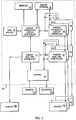
- FIGURE 1 is an illustration of a document assembly system, indicated generally at 10, according to the preferred embodiment.
- document assembly system 10 is a comprehensive perfect bindery system that assembles documents bound with glue, as compared with other binding materials such as staples or stitches.
- Exemplary types of documents are a book, a magazine, and a newspaper.
- a document “edition” is a set of documents assembled by document assembly system 10 in response to a particular setup and configuration.
- a “generic” document is material common to all documents of a document edition.
- a “custom” document is a generic document having content not common to all documents of a document edition.
- Document assembly system 10 includes a gather section indicated generally by dashed enclosure 12, a binder section indicated generally by dashed enclosure 14, a dry cure table section indicated generally by dashed enclosure 16, and a trimmer section indicated generally by dashed enclosure 18. Together, gather section 12, binder section 14, dry cure table section 16, and trimmer section 18 form a document assembly line of document assembly system 10.
- Document assembly system 10 further includes a control system indicated generally by dashed enclosure 20.
- control system 20 has a distributed architecture.
- control system 20 includes a bindery application station controller ("BASC") 22, a bindery real time controller (“BRTC") 24, zero or more printer application station controllers (“PASC”) 26, and zero or more printer real time controllers (“PRTC”) 28 each associated with a respective PASC 26.
- BASC bindery application station controller
- BRTC bindery real time controller
- PASC printer application station controllers
- PRTC printer real time controllers
- control system 20 includes an input/output ("I/O") panel 30, a marquee 32, and a tape reader 34.
- Control system 20 further includes a remote terminal 36 located proximate to gather section 12. Interrelations between the various elements of control system 20 are discussed further hereinbelow in connection with FIGURE 2.
- Gather section 12 includes multiple paper feeders ("gather pockets") 40a-g disposed over a conveyor 42.
- FIGURE 1 shows seven gather pockets, although gather section 12 can include numerous additional gather pockets.
- gather pockets 40a-g and conveyor 42 selectively gather one or more signatures (not shown in FIGURE 1) for one or more documents.
- control system 20 operates gather section 12 to selectively gather sets of signatures for multiple customized versions of one or more documents, contemporaneously.
- Conveyor 42 leads sets of gathered signatures from gather section 12 to a conveyor 44 of binder section 14. Conveyor 44 further leads the sets of gathered signatures into a binder unit 46 of binder section 14. Binder section 14 also includes multiple cover paper feeders ("cover pockets") 48a-d disposed over a conveyor 50. In response to signals from control system 20, cover pockets 48a-d and conveyor 50 selectively lead one or more covers (not shown in FIGURE 1) for one or more documents into binder unit 46. Using glue, binder unit 46 binds each set of gathered signatures from conveyor 44 with one or more covers from conveyor 50.
- a conveyor 51 leads sets of bound and covered signatures from binder unit 46 to a conveyor 52 of dry cure table section 16. The sets of bound and covered signatures are conveyed along conveyor 52, so that their glues are allowed to dry and/or cure. Conveyor 52 leads sets of dried signatures to a conveyor 54 of trimmer section 18.
- Conveyor 54 leads the sets of dried/cured signatures into a trimmer unit 56 of trimmer section 18. Trimmer unit 56 trims the sets of dried/cured signatures to form documents. Conveyor 54 leads the documents out of trimmer unit 56 to a stacker unit 58. In response to signals from control system 20, stacker unit 58 selectively stacks documents from conveyor 54 into one or more groups 60a-b conveyed on a conveyor 62.
- Document assembly system 10 further includes one or more divert gates, such as divert gates 64a-c shown in FIGURE 1.
- control system 20 operates divert gates 64a-c to selectively divert objects in response to errors detected during assembly of documents.
- divert gate 64a selectively diverts one or more sets of gathered signatures away from conveyor 44 of binder section 14.
- divert gate 64b selectively diverts one or more sets of bound and covered signatures away from conveyor 52 of dry cure table section 16.
- divert gate 64c selectively diverts one or more documents to a conveyor 65 away from stacker 58.
- document assembly system 10 includes one or more image stations, such as printers 66a and 66b shown in FIGURE 1.
- control system 20 operates printer 66a to print identification information on covers of bound signatures after they exit binder unit 46 along conveyor 51.
- control system 20 subsequently reads the printed identification information through an optical scanner 68 from covers of documents after they exit trimmer unit 56 along conveyor 54.
- Control system 20 operates printer 66b to selectively print subscriber information, such as addresses and notices on covers of documents after they exit trimmer unit 56 along conveyor 54.
- Control system 20 is further able to operate one or more additional printers to selectively print subscriber information anywhere on or within a document.
- FIGURE 2 is a block diagram of control system 20.
- Tape reader 34 is connected to BASC 22 for inputting, storing, and outputting subscriber information.
- Remote terminal 36 stores configuration and setup information concerning document assembly system 10.
- BASC 22 inputs configuration and setup information from remote terminal 36.
- remote terminal 36 modifies its stored configuration and setup information.
- Marquee 32 displays information to an operator in response to signals from BASC 22.
- Remote terminal 36 operates as a remote host controller. Accordingly, remote terminal 36 includes a resident database for storing information relating to interfaces with an operator. The resident database of remote terminal 36 is accessible by remote terminal 36, BASC 22 and PASC 26.
- remote terminal 36, BASC 22 and PASC 26 each include a respective display screen and input device, such as a keyboard or pointing device, for interfacing with the operator. Through any such input device, the operator sends instructions to one or more of remote terminal 36, BASC 22 and PASC 26. For example, through the input device of remote terminal 36, the operator can modify configuration and setup information.
- BRTC 24 inputs signals from sensors 100, including miss sensors, verify sensors, pocket sensors, and print demand sensors (not shown) as discussed further hereinbelow in connection with FIGURES 3 and 6a-b. Moreover, through I/O panel 30, BRTC 24 outputs signals to actuators 102 for selectively operating elements of document assembly system 10, including gather pockets 40a-g, cover pockets 48a-c, and divert gates 64a-c.
- BASC 22 operates as a bindery host controller. Accordingly, BASC 22 outputs signals to BRTC 24 and to PASC 26 for coordinating assembly of multiple documents according to the preferred embodiment. From BRTC 24 and PASC 26, BASC 22 inputs status information relating to document assembly operations.
- BRTC 24 outputs signals to printer 66a for printing identification information on covers of bound signatures after they exit binder unit 46 along conveyor 51.
- PRTC 28 outputs signals to respective printer 66b for selectively printing on a cover or signatures of an individual document. Status information is communicated between BRTC 24 and PRTC 28, so that such printing operations are synchronized with other operations of document assembly system 10.
- PASCs 26 operates as print host controllers. Accordingly, PASC 26 outputs signals to a respective PRTC 28 for coordinating printing on multiple documents. From PRTC 28, PASC 26 inputs status information relating to printing operations. For each additional printer 104 added to document assembly system 10, an additional PRTC 106 and PASC 108 can be added to control system 20 as shown in FIGURE 2.
- BASC 22, PASC 26 and remote terminal 36 are PS/2 computers available from INTERNATIONAL BUSINESS MACHINES CORPORATION, executing C language instructions in an OS/2 1.2 operating environment.
- BRTC 24 and PRTC 28 are VME based multi-processor systems, executing C++ language instructions in a Realtime Multiprocessing Kernel ("RMK") operating environment available from INTERNATIONAL BUSINESS MACHINES CORPORATION. Instructions are structured as sets of communicating processes, as discussed further hereinbelow in connection with FIGURE 8.
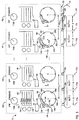
- FIGURE 3 is an illustration of gather section 12.
- FIGURE 3 shows substantially identical gather pockets 40a-b and 40f-g (indicated generally by dashed enclosures), although gather section 12 can include numerous additional gather pockets. Gather pockets 40a-b and 40f-g are disposed over conveyor 42. Conveyor 42 includes multiple substantially equally spaced pins 128a-f shown in FIGURE 3, although conveyor 42 can include numerous additional pins.
- Gather pocket 40a is a representative one of gather pockets 40a-b and 40f-g. Accordingly, for clarity, only gather pocket 40a is discussed in detail hereinbelow. Gather pocket 40a includes a mode device 130 for switching gather pocket 40a between "time”, “off", and “standard” modes. Further, gather pocket 40a includes a vacuum device 132, a "miss” light 134, and a “double” light 136, each coupled through actuators 102 to I/O panel 30 of FIGURE 2. Moreover, gather pocket 40a includes a caliper sensor 138 and a miss sensor 140, each connected as sensors 100 to I/O panel 30 of FIGURE 2. In the preferred embodiment, miss sensor 140 is a photosensor.
- Gather pocket 40a also includes a drum 142.
- drum 142 rotates in the direction indicated generally by arrow 144.
- Drum 142 includes grippers 146a-c and respectively associated miss activation elements 148a-c.
- drum 142 includes an index activation element 150.
- activation elements 148a-c and 150 are reflectors.
- gather pocket 40a includes a hopper 152. Hopper 152 holds a set of substantially identical signatures 154a-e.
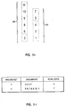
- FIGURE 4 is an illustration of exemplary signature 154a.
- Signature 154a is a single sheet of paper, indicated generally at 156, on which multiple pages 158a-f of a document are printed. After pages 158a-f are printed on paper 156, paper 156 is folded along lines 160a-c to form signature 154a.
- document assembly system 10 assembles a document by gathering different signatures from multiple ones of gather pockets 40a-g.
- Trimmer unit 56 trims sets of dried/cured signatures to form multiple sheets of paper properly oriented and sequenced within a document. Accordingly, the length L and width W of signature 154a are slightly greater than the length and width of a document in which signature 154a is to be included.
- the nominal spacing between sequential ones of gather pockets 40a-g is a distance A as shown in FIGURE 3.
- the nominal spacing between gather pockets 40a and 40b is distance A.
- distance A is twenty-seven inches.
- the nominal spacing between sequential ones of pins 128a-f is a distance B as shown in FIGURE 3.
- the nominal spacing between pins 128a and 128b is distance B.
- distance B is 40,64 cm (sixteen inches).
- slots are defined relative to conveyor 42 and are numbered as slot 0 through slot n-1 as shown in FIGURE 3, where n is the total number of defined slots.
- n is the total number of defined slots.
- each of slots 0 through n-1 has a length equal to distance B. Accordingly, n ⁇ A ⁇ number of gather pockets B .
- slots are defined for all conveyors of document assembly system 10.
- conveyor 42 shifts pins 128a-f in the direction indicated generally by arrow 170.
- all of pins 128a-f are simultaneously alignable with boundaries 172a-f of slots 0 through n-1.
- pins 128a-f can be offset from boundaries 172a-f as conveyor 42 shifts pins 128a-f in the direction indicated generally by arrow 170.
- any of pins 128a-f is alignable with any of boundaries 172a-f.
- the shifting of pins 128a-f does not modify the positions of slots 0 through n-1 relative to conveyor 42.
- Pins 128a-f are arranged in a continuous chain so that, after conveyor 42 shifts a pin across boundary 172f, conveyor 42 eventually returns the pin to entry boundary 172a.
- slot 0 of gather section 12 is an entry point for document assembly system 10 at which assembly of documents begins. In an alternative embodiment, the entry point is a different slot of gather section 12.
- mode device 130 is switched to a "standard” setting, so that gather pocket 40a is responsive to control signals from control system 20.
- each of gather pockets 40b and 40f-g are switched to a "standard” setting.
- control system 20 selectively operates a gather pocket's vacuum device to pull a signature from the gather pocket's hopper.
- control system 20 selectively operates a vacuum device 180 to pull a signature 182 from a hopper 184.
- a gather pocket's vacuum device pulls a signature from the gather pocket's hopper
- the pulled signature is gripped by a gripper of the gather pocket's drum.
- a gripper of the gather pocket's drum For example, referring to gather pocket 40f, a pulled signature 190 is gripped by a gripper 192 of a drum 194.
- a caliper sensor 196 measures thickness of signature 190 to detect whether multiple signatures are errantly being gripped simultaneously by gripper 192.
- Cover pockets 48a-d (FIGURE 1) operate in a similar manner. Notably, cover pockets 48a-d do not include caliper sensors.
- control system 20 selectively gathers signatures in a set to form a document. For example, in FIGURE 3, signatures 197a-b are gathered in a set between pins 128e and 128f to form part or all of a particular document.
- control system 20 operates gather section 12 to selectively gather sets of signatures for multiple customized versions of one or more documents, contemporaneously.
- Each gather pocket's drum is positioned proximate to an associated miss sensor.
- drum 142 of gather pocket 40a is positioned proximate to miss sensor 140
- drum 194 of gather pocket 40f is positioned proximate to a miss sensor 198.
- drum 194 of gather pocket 40f includes grippers 192, 200 and 202, and respectively associated miss activation elements 204a-c.
- drum 194 includes an index activation element 206.
- miss activation element When a signature is not being gripped by a miss activation element's associated gripper, the miss activation element is not covered. For example, referring to gather pocket 40a, a signature is not being gripped by gripper 146a associated with miss activation element 148a, so that miss activation element 148a is not covered. In such a situation, the gather pocket's miss sensor detects an activation of the miss activation element when the miss activation element is positioned proximate to the miss sensor.
- miss sensor 140 detects an activation of miss activation element 148a when drum 142 eventually rotates miss activation element 148a into a region indicated generally by dashed enclosure 210 proximate to miss sensor 140.
- index activation element 150 is positioned within region 210 proximate to miss sensor 140, so that miss sensor 140 detects an activation of index activation element 150.
- a miss sensor detects an activation of an activation element by detecting a reflection of light from the activation element.
- miss activation element When a signature is being gripped by a miss activation element's associated gripper, the miss activation element is covered by the signature. For example, referring to gather pocket 40f, signature 190 is being gripped by gripper 192 associated with miss activation element 204a, so that miss activation element 204a is covered by signature 190. In such a situation, the gather pocket's miss sensor does not detect an activation of the miss activation element, even when the miss activation element is positioned proximate to the miss sensor.
- control system 20 determines whether a signature is being gripped.
- the index activation element is never covered, even when a signature is being gripped, such that the miss sensor always detects an activation of an index activation element positioned proximate to the miss sensor.
- a cycle is an event in which conveyor 42 shifts all of pins 128a-f over the length B of a slot. Further, during each cycle, each drum rotates approximately 120 degrees. Accordingly, a gather pocket's miss sensor detects an activation of the gather pocket's index activation element once every three cycles.
- FIGURE 5 is a timing diagram of signals processed by control system 20 according to the calibrating technique of the preferred embodiment. From each of gather pockets 40a-g (FIGURE 1), control system 20 inputs a miss sensor signal 220 through I/O panel 30 (FIGURE 2). From conveyor 42 (FIGURE 1), control system 20 inputs a pin clock signal 222 through I/O panel 30. Pin clock signal 222 has a positive pulse once per cycle, thereby indicating when all of pins 128a-f have been shifted by conveyor 42 over the length B of a slot.
- control system 20 From conveyor 42, control system 20 inputs an encoder pulse signal 224 through I/O panel 30. In response to conveyor 42 shifting all of pins 128a-f over a unit distance, encoder pulse signal 224 has a positive pulse. In an exemplary embodiment, such a unit distance is 1/720 of an inch.
- control system 20 increments an encoder pulse count in response to each pulse of encoder pulse signal 224.
- a cycle is an event in which conveyor 42 shifts all of pins 128a-f over the length B of a slot; accordingly, x is a predetermined constant number of pulses output by gather section 12 per cycle, and a fraction of x pulses is linearly related to a fraction of a cycle.
- control system 20 In response to each positive pulse of pin clock signal 222, control system 20 resets the encoder pulse count to 0 pulses and continues incrementing the encoder pulse count in response to each pulse of encoder pulse signal 224.
- miss sensor signal 220 a gather pocket's miss sensor outputs a positive pulse each time it detects an activation of any of the gather pocket's activation elements, including the index activation element and the miss activation elements.
- miss sensor signal 220 illustrates a situation where no signatures are being gripped by the gather pocket's drum, so that miss sensor signal 220 has four positive pulses 228a-d per 360 degree rotation (three cycles) of the gather pocket's drum.
- miss sensor signal 220 has one positive pulse per cycle attributable to an activation of a miss activation element, such as pulses 228a, 228c and 228d. Moreover, miss sensor signal 220 has one positive pulse per three cycles attributable to an activation of an index activation element, such as pulse 228b. Thus, for one of every three cycles, miss sensor signal 220 has two positive pulses (one pulse attributable to an activation of a miss activation element and another pulse attributable to an activation of an index activation element), such as pulses 228a and 228b.
- control system 20 identifies pulses 228a, 228c and 228d as being attributable to a miss sensor's detecting activations of miss sensor elements. Moreover, as illustrated in FIGURE 5, pulses 228a, 228c and 228d occur at similar encoder pulse counts, thereby according with the substantially equal spacing of miss activation elements around a gather pocket's drum.
- control system 20 relates pulses 228a-d to the encoder pulse count of curve 226.
- the encoder pulse count of curve 226 is related to pin clock signal 222 and to physical positions of pins and slots of conveyor 42.
- pulses 228a-d are related to physical positions of activation elements around a gather pocket's drum. Accordingly, by relating pulses 228a-d to the encoder pulse count of curve 226, control system 20 advantageously relates physical positions of activation elements around a gather pocket's drum to physical positions of pins and slots of conveyor 42.
- each drum of cover pockets 48a-d has two substantially evenly spaced miss activation elements and no index activation element. Accordingly, a cycle for cover pockets 48a-d is an event in which each drum rotates approximately 180 degrees, so that each cover pocket's miss sensor detects an activation of a miss activation element once per cycle.
- control system 20 inputs a respective pin clock signal from different conveyors of document assembly system 10. Also, control system 20 inputs a respective encoder pulse signal from different conveyors of document assembly system 10. Accordingly, control system 20 adjusts to differences in physical positions of pins and slots of different conveyors.
- control system 20 For example, from each of cover pockets 48a-d (FIGURE 1), control system 20 inputs a miss sensor signal through I/O panel 30 (FIGURE 2). From conveyor 50, control system 20 inputs a pin clock signal and an encoder pulse signal through I/O panel 30. In response to such signals, control system 20 relates physical positions of activation elements around drums of cover pockets 48a-d to physical positions of pins and slots of conveyor 50 (FIGURE 1) according to the technique discussed hereinabove in connection with FIGURE 5 for gather pockets.
- FIGURE 6 is data flow diagram of a technique for operating document assembly system 10 according to control system 20.
- the data flow diagram includes multiple queues, each operating as a first-in first-out buffer.
- Control system 20 represents all slots of the gather section as logical book record locations in a gather fixed queue.
- control system 20 represents all slots of the binder section, and the trimmer section as logical book record locations in a binder fixed queue and a trimmer fixed queue, respectively.
- Control system 20 represents signature sets along conveyor 52 of dry cure section 16 as logical book records, each associated with a unique document identification number, in the dry cure table of FIGURE 6. If no signatures are present at a slot, then the slot's corresponding logical book record location is occupied by a null record. If one or more signatures is present at a slot, then the slot's corresponding logical book record location is occupied by the logical book record of the document being assembled in the slot.
- output from the gather fixed queue is directed to the front of the binder fixed queue.
- Output of the binder fixed queue is directed to the front of the dry cure table, and output of the dry cure table is directed to the front of the trimmer fixed queue.
- Output of the trimmer fixed queue is directed to the divert process for representation as being suitably diverted by divert gate 64c (FIGURE 1).
- output of the gather fixed queue is optionally directed to the divert process for representation as being suitably diverted by divert gate 64a (FIGURE 1).
- output of the binder fixed queue is optionally directed to the divert process for representation as being suitably diverted by divert gate 64b (FIGURE 1).
- Divert gate locations are specified to the divert process as slot locations from configuration data.
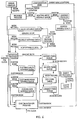
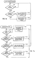
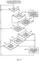
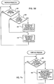
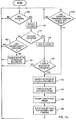
- FIGURES 7a-e are flow charts of processes of the operating technique of FIGURE 6.
- the host receive process begins at a decision block 400, where execution loops until a document is to be ordered according to an initial document order.
- control system 20 determines at a decision block 402 whether the document to be ordered is a quality document. Quality documents are discussed further herein below in connection with FIGURES 9a-11b.
- control system 20 adds the quality document's logical book record to the quality variable queue. After step 404, execution returns to decision block 400. If control system 20 determines at decision block 402 that the document to be ordered is not a quality document, then at a step 406 control system 20 adds the document's logical book record to the new variable queue. After step 406, execution returns to decision block 400.
- the initiation process begins at a decision block 410, where execution loops until a new cycle occurs for gather section 12.
- control system 20 determines at a decision block 412 whether a logical book record exists in the quality variable queue. If a logical book record exists in the quality variable queue, then control system 20 moves the logical book record into the custom quality variable queue at a step 414. After step 414, execution continues to a step 416 where control system adds a generic document record to the gather fixed queue. Execution then returns to decision block 410.
- control system 20 determines at a decision block 412 that no logical book record exists in the quality variable queue, then control system 20 determines at a decision block 418 whether a logical book record exists in the reorder variable queue. If a logical book record exists in the reorder variable queue, then control system 20 moves the logical book record into the gather fixed queue at a step 420. After step 420, execution returns to decision block 410.
- control system 20 determines at a decision block 418 that no logical book record exists in the reorder variable queue, then control system 20 determines at a decision block 422 whether a logical book record exists in the new variable queue. If a logical book record exists in the new variable queue, then control system 20 moves the logical book record into the custom new variable queue at a step 424. After step 424, execution continues to step 416.
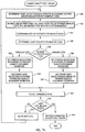
- the custom initiation process begins at a decision block 430, where execution loops until a new cycle occurs.
- control system 20 determines at a decision block 432 whether a logical book record exists in the sorted variable queue. In a significant aspect of the preferred embodiment, if a logical book record exists in the sorted variable queue, then control system 20 determines at a decision block 434 whether all preceding documents in the sequence of the initial document order have been processed so that such preceding documents are no longer being assembled by document assembly system 10.
- control system 20 determines at decision block 434 that all preceding documents in the sequence of the initial document order have been processed, then execution continues to a step 436 where control system 20 moves the logical book record from the sorted variable queue into the custom reorder variable queue. Accordingly, at step 436, control system 20 reorders document assembly system 10 to assemble a replacement for an errantly assembled custom document. Execution then returns to decision block 432.
- control system 20 determines at decision block 432 that no logical book record exists in the sorted variable queue, or if control system 20 determines at decision block 434 that not all preceding documents in the sequence of the initial document order have been processed, then execution continues to a decision block 438 where control system 20 determines whether a generic document is present at the customization location.
- the customization location is a predetermined slot of document assembly system 10 at which assembly of custom documents begins.
- a "custom" document is a generic document having content not common to all documents of a document edition. Control system 20 automatically determines the customization location in response to setup and configuration information.
- control system 20 determines at decision block 438 that a generic document is not present at the customization location, then execution returns to decision block 430. If a generic document is present at the customization location, then execution continues to a decision block 440 where control system 20 determines whether a logical book record exists in the custom quality variable queue. If not, then execution continues to a decision block 442 where control system 20 determines whether a logical book record exists in the custom reorder queue. If not, then execution continues to a decision block 444 where control system 20 determines whether a logical book record exists in the custom new variable queue. If not, then execution returns to decision block 430.
- control system 20 determines at decision block 440 that a logical book record exists in the custom quality variable queue, or if control system 20 determines at decision block 442 that a logical book record exists in the custom reorder variable queue, or if control system 20 determines at decision block 444 that a logical book record exists in the custom new variable queue, then execution continues to a step 446.
- control system 20 moves the custom document's logical book record to replace a generic logical book record at the customization record location.
- the customization record location can be located in either the gather fixed queue, the binder fixed queue, or the trimmer fixed queue, depending upon which section includes the customization location of document assembly system 10. Accordingly, at decision block 430, execution loops until a new cycle occurs for the section of document assembly system 10 having the customization location. After step 446, execution returns to decision block 430.
- the reorder process begins at a decision block 450 where execution loops until an error in assembly of a document is detected and processed by the error handler (FIGURE 6).
- control system 20 determines at a decision block 452 whether the errantly assembled document is at or beyond the customization location. If the errantly assembled document is at or beyond the customization location, then execution continues to a step 454 where control system 20 adds the errantly assembled document's logical book record to the sorting input variable queue.
- step 454 execution continues to a step 456 where control system 20 adds a generic logical book record to the reorder variable queue.
- control system plans for a generic document to be present at the customization location when control system 20 reorders document assembly system 10 to assemble a replacement for the errantly assembled document (in the manner discussed hereinabove in connection with decision block 442 and step 446 of FIGURE 7c).
- step 456 execution returns to decision block 450. If control system 20 determines at decision block 452 that the errantly assembled document is before the customization location, then execution continues to step 456.
- the sorting process begins at a decision block 458 where execution loops until control system 20 determines that a logical book record exists in the sorting input variable queue.
- execution continues to a step 460 where control system 20 moves the errantly assembled document's logical book record into the sorted variable queue according to the sequence of the initial document order. Accordingly, control system 20 is able to rearrange the order of logical book records in the sorted variable queue so that document assembly system 10 assembles replacements for the errantly assembled documents according to the sequence of the initial document order.
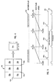
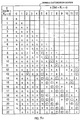
- FIGURES 8a-c are illustrations of an exemplary operation of document assembly system 10 according to the operating technique of FIGURE 6.
- FIGURE 8a illustrates the status of various documents in slots K1 through (K1+12) during multiple cycles K2 through (K2+22) in response to an initial order for the sequence of custom documents-1, 2, 3, 4, 5, 6, 7, 8, 9, 10 and 11.
- the customization location is slot (K1+5).
- control system 20 initiates assembly of a generic document at the entry location (slot 0 of gather section 12) of document assembly system 10 in response to each cycle. Referring to FIGURE 8a, control system 20 initiates assembly of a generic document G at slot (K1+0) during cycle (K2+0).
- control system 20 initiates assembly of an additional generic document at slot (K1+0) Accordingly, at cycle (K2+1), generic documents are being assembled by document assembly system 10 at slots (K1+0) and (K1+1).
- the generic document initiated at slot (K1+0) during cycle (K2+0) eventually propagates through the slots until it reaches the customization slot (K1+5) during cycle (K2+5).
- control system 20 orders document assembly system 10 to begin customizing the generic document as custom document-1.
- custom document-1 continues propagating through the slots, and document assembly system 10 begins customizing additional generic documents as shown in FIGURE 8a as custom documents-1, 2, 3, and 4.
- control system 20 detects an improperly assembled document in response to signals from one or more miss sensors, entry sensors, verify sensors, and caliper sensors.
- an improperly assembled document is diverted at the earliest possible divert gate.
- the triangular border at slot (K1+5) during cycle (K2+8) indicates that custom document-4 was subject to an error in assembly at slot (K1+5) during cycle (K2+8). Accordingly, custom document-4 is diverted at the earliest possible divert gate, which is located after slot (K1+8) in the example of FIGURE 8a. Notably, documents are subject to errors in a random order independent of the initial document order.
- control system 20 reorders document assembly system 10 to assemble replacements for the errantly assembled custom documents according to their sequence in the initial document order.
- document assembly system 10 advantageously assists in maintaining the initial presorting of documents to preserve postage savings for bulk mailings, even where replacement documents are assembled. Moreover, document assembly system 10 does not purge properly assembled documents in order to assemble a replacement for an errantly assembled document. Further, document assembly system 10 does not stop the operation of its document assembly line in order to assemble a replacement for an errantly assembled document.
- control system 20 achieves this advantage by imposing a condition that all preceding documents in the sequence of the initial document order be processed (so that such preceding documents are no longer being assembled by document assembly system 10) prior to reordering document assembly system 10 to assemble a replacement for an errantly assembled custom document.
- control system 20 reorders document assembly system 10 to assemble a replacement for custom document-1 at the earliest opportunity, as indicated in FIGURE 8a by the circular boundary at slot (K1+5) during cycle (K2+13).
- control system 20 advantageously reorders document assembly system 10 to assemble a replacement for custom document-1 beginning at a point along the document assembly line after the entry point of document assembly system 10.
- control system 20 reorders document assembly system 10 to assemble a replacement for custom document-1 beginning at the customization point, so that the replacement for custom document-1 is located as proximately as possible to the original position of custom document-1 in the initial document order.
- control system 20 reorders document assembly system 10 to assemble a replacement for custom document-2 as indicated in FIGURE 8a by the circular boundary at slot (K1+5) during cycle (K2+14).
- control system 20 reorders document assembly system 10 to assemble a replacement for custom document-4 as indicated in FIGURE 8a by the circular boundary at slot (K1+5) during cycle (K2+17).
- control system 20 readily reassigns replacement documents to their respective mailing groups.
- control system 20 operates divert gate 64c (FIGURE 1) to divert a replacement set 430 having replacements for custom documents-1, 2, 4, 5 and 7 to conveyor 65 (FIGURE 1) according to the sequence of the initial document order.
- Document assembly system 10 outputs a set 432 of original custom documents-3, 6, 8, 9, 10 and 11 to conveyor 62 according to the sequence of the initial document order.
- FIGURE 8c lists instructions to group a total of four custom documents-1, 2, 3 and 4 into a mailing set I. Moreover, FIGURE 8c lists instructions to group a total of seven custom documents-5, 6, 7, 8, 9, 10 and 11 into a mailing set II. In response to such instructions, control system 20 readily reassigns replacement documents to their respective mailing sets.
- control system 20 determines that the only properly assembled member of mailing set I in set 432 is original custom document-3, which is three short of the total number of documents in mailing set I. Since replacement set 430 accords with the sequence of the initial document order, control system 20 readily reassigns the first three replacements in replacement set 430 to complete mailing set I in combination with original custom document-3.
- control system 20 determines that the only properly assembled members of mailing set II in set 432 are original custom documents-6, 8, 9, 10 and 11, which are two short of the total number of documents in mailing set II. Since replacement set 430 accords with the sequence of the initial document order, control system 20 readily reassigns the next two replacements in replacement set 430 to complete mailing set II in combination with original custom documents-6, 8, 9, 10 and 11.
- control system 20 tracks the order of documents along the perfect bindery line and suitably reorders documents along a single path between two points, so that additional paths and equipment are not required to be added to a conventional perfect bindery line in order to suitably reorder documents.
- FIGURES 9a-c are a flow chart of a technique for monitoring document assembly system 10 according to control system 20.
- control system 20 advantageously supports the assembly of supplemental ("quality") documents in order to monitor proper assembly and quality of the regular documents being assembled.
- quality supplemental
- documents are customised so that a document's type is identified by a makeup code discussed further hereinbelow in connection with FIGURE 10a.
- Control system 20 operates document assembly system 10 to assemble quality documents in response to two types of orders: (1) manual orders placed on demand by an operator and (2) periodic orders automatically placed by control system 20.
- Each type of order has its own parameter definition information. For example, the operator can specify that periodically ordered quality documents print at all configured printers even while manually ordered documents are specified to print at selected ones of the printers.
- control system 20 supports several configurable attributes of quality documents which can be specified by the operator. These attributes are (1) the makeup code definitions for the contents of quality documents to be assembled, (2) the number of quality documents to be assembled as part of each quality document order, (3) whether to periodically initiate assembly of one or more quality documents automatically and, if so, the number ("frequency") of regular documents to assemble before periodically initiating a quality document order (if the operator specifies 0 number of regular documents to assemble, then periodic initiation is disabled), (4) the list of configured printers to print on each quality document, (5) the divert gate at which each quality document is to be diverted, and (6) whether to print a fact sheet for each assembled quality document.
- attributes are (1) the makeup code definitions for the contents of quality documents to be assembled, (2) the number of quality documents to be assembled as part of each quality document order, (3) whether to periodically initiate assembly of one or more quality documents automatically and, if so, the number (“frequency") of regular documents to assemble before periodically initiating a quality document order (if the operator specifies 0 number of regular documents to
- signatures are reusable if the divert gate is located prior to binder section 14 and if the signatures are not printed upon.
- Periodically ordered quality documents are the only type of quality documents having a frequency attribute.
- Control system 20 inputs operator specified initial values for the quality document parameters.
- Control system 20 accepts modifications to any parameter during assembly of a document edition. After control system 20 stores such modifications, the modifications are effective when control system 20 initiates the next quality document order.
- control system 20 preserves initial values and modifications thereto, so that both initial values and modifications thereto are reusable. Modifications made during assembly of a document edition are effective only for the remainder of the assembly of the document edition.
- execution begins in parallel at decision blocks 450a and 450b.
- decision block 450a execution loops until control system 20 determines that the operator has manually placed a quality document order. If the operator manually places a quality document order, execution continues to a step 452.
- control system 20 determines whether the initiated document is a regular document.
- control system 20 increments a count of regular documents. After step 456, control system 20 determines at a decision block 458 whether the count is a multiple of the operator-specified frequency for quality document orders periodically placed by control system 20. If the count is a multiple of the operator-specified frequency, then execution continues to step 452. If the count is not a multiple of the operator-specified frequency, then execution returns to decision blocks 450a and 450b.
- control system 20 determines at decision block 454 that the initiated document is not a regular document, then execution continues to a decision block 460.
- decision block 460 control system 20 determines whether assembly of the last queued quality document has been initiated. If not, then execution returns to decision blocks 450a and 450b. If assembly of the last queued quality document has been initiated, then execution continues to a step 461 where control system 20 reenables further initiation of regular documents. After step 461, execution returns to decision blocks 450a and 450b.
- control system 20 disables further initiation of regular document orders until all ordered quality documents are initiated. Moreover, manually ordered quality documents have priority over periodically ordered quality documents, so that control system 20 inhibits the initiation of periodically ordered quality documents until all manually ordered documents are initiated.
- Control system 20 gives manually ordered quality documents priority over periodically ordered quality documents, since an operator is likely to physically wait for assembly of manually ordered quality documents.
- control system 20 creates a quality document order at step 462 as discussed further hereinbelow in connection with FIGURE 9b and FIGURE 10d.
- control system 20 formats the quality document order at a step 464 as discussed further hereinbelow in connection with FIGURE 9c and FIGURE 10e.
- control system 20 queues quality documents for assembly and printing. After step 466, execution returns to decision blocks 450a and 450b.
- control system 20 creates a quality document order (step 462 of FIGURE 11a) beginning at a decision block 470.
- An exemplary quality document order is shown in FIGURE 10d discussed further hereinbelow.
- control system 20 determines whether the quality document order is (1) a manual order placed on demand by an operator or (2) a periodic order automatically placed by control system 20. If the quality document order is a periodic order, then at a step 472 control system 20 reads a makeup code table pointer and a dummy identification for the periodic order. If the quality document is a manual order, then at a step 474 control system 20 reads a makeup code table pointer and a dummy identification for the manual order. Makeup codes are discussed further hereinbelow in connection with FIGURE 10a.
- control system 20 determines whether the operator has specified multiple makeup code definitions through which control system 20 is to cycle. If not, then execution continues to a step 478. Otherwise, if the operator has specified that control system 20 is to cycle through multiple makeup code definitions, then control system increments the makeup code table pointer at a step 480. After step 480, execution continues to step 478.
- control system 20 reads the makeup code from the makeup code table according to the makeup code table pointer and then writes the makeup code into a quality document order block as discussed further hereinbelow in connection with FIGURE 10d.
- control system 20 writes the dummy identification into the quality document order block.
- control system 20 establishes a dummy identification for the next quality document.
- control system 20 determines at a decision block 486 whether any additional quality documents remain to be created in the quality document order. If so, then execution returns to decision block 476. If no more quality documents remain to be created, then execution continues to a step 488 where control system 20 returns the quality document order block.
- control system 20 formats a quality document order (step 464 of FIGURE 11a) beginning at a step 490.
- An exemplary formatted quality document order is shown in FIGURE 10e discussed further hereinbelow.
- control system 20 determines the print field layout for each printer of document assembly system 10, according to a print group associated with the quality document's makeup code as discussed further hereinbelow in connection with FIGURE 10a.
- control system 20 fills the first four fields with the quality document's makeup code. Remaining print area is filled with alphanumerics as discussed further herein below in connection with FIGURE 13b.
- control system 20 determines gather pockets for the quality document's makeup code. After determining gather pockets, control system 20 determines cover pocket(s) for the quality document's makeup code at a step 496.
- control system 20 determines at a decision block 498 whether the quality document order is (1) a manual order placed on demand by an operator or (2) a periodic order automatically placed by control system 20. If the quality document order is a periodic order, then at a step 500 control system 20 sets printer selections according to the definition of the periodically ordered quality document. Then, at a step 502, control system 20 sets divert gate selections according to the definition of the periodically ordered quality document. After step 502, execution continues to a step 504.
- control system 20 determines at decision block 498 that the quality document order is a manual order, then at a step 506 control system 20 sets printer selections according to the definition of the manually ordered quality document. Then, at a step 508, control system 20 sets divert gate selections according to the definition of the manually ordered quality document. After step 508, execution continues to step 504.
- control system 20 stores the formatted print data, pocket data, and divert gate data for the quality document order as discussed further hereinbelow in connection with FIGURE 12e. Then, at a decision block 510, control system 20 determines whether any additional quality documents remain to be formatted in the quality document data block. If additional quality documents remain to be formatted, then execution continues to a step 512 where control system 20 determines the next quality document to process. After step 512, execution returns to step 490. If control system 20 determines at decision block 510 that no additional quality documents remain to be formatted, then execution continues to a step 514 where control system 20 returns the formatted quality document order.
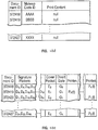
- FIGURES 10a-e are illustrations of information records processed by control system 20 according to the monitoring technique of FIGURES 11a-c. Together, FIGURES 10a-c illustrate a setup record for a document edition.
- control system 20 initiates a quality document order
- control system 20 generates simulated tape information for each quality document to be assembled.
- Such simulated tape information includes the makeup code selected for each quality document.
- the simulated tape information is distributed in a similar manner as regular tape information.
- each defined makeup code has an identification (e.g. "AAAA").
- Each makeup code defines a cover and a set of signatures for a document.
- each makeup code defines a print group for each printer of document assembly system 10.
- Table 1 shows exemplary print groups for a particular printer.
- Exemplary Print Groups Print Group Name Print Information P1 address 6 lines of address as specified in database P2 address/renew 6 lines of address as specified in database and renewal message P3 null None If a makeup code does not specify a print group for a particular printer, then the printer is not used in assembling documents according to the makeup code.
- each of gather pockets D1-Dn is listed as feeding a specified signature (e.g. S4). If “null” is specified for a gather pocket (e.g. D2), then the gather pocket is not used.
- each of cover pockets E1-Er is listed as feeding a specified cover (e.g. C2). If “null” is specified for a cover pocket (e.g. Er), then the cover pocket is not used.
- FIGURE 10d illustrates a document order block as formed at step 478 of FIGURE 9b.
- each document has an identification number and a makeup code.
- the quality document makeup code identification is associated with print content for the quality document.
- FIGURE 10e illustrates a formatted quality document order.
- the formatted quality document order merges various information of FIGURES 10a-d. Accordingly, for a document identified in FIGURE 12d having a particular makeup code, FIGURE 10e lists actual signature pockets used in assembling the document according to FIGURES 10a and 10b. Similarly, FIGURE 12e lists actual cover pocket(s) used in assembling the document according to FIGURES 10a and 10c. Further, FIGURE 10e lists a respective divert gate and includes formatted print groups for enabled printers.
- FIGURES 11a-b are illustrations of an exemplary operation of document assembly system 10 according to the monitoring technique of FIGURES 9a-c.
- FIGURE 11a illustrates assembly by document assembly system 10 of quality documents in response to (1) a manual order of quality documents placed on demand by the operator and (2) a periodic order of quality documents automatically placed by control system 20.
- Regular documents are being assembled in slots (K1+12) through (K1+15).
- control system 20 After initiating assembly of a specified number (e.g. 1000) of regular documents, control system 20 automatically initiates assembly of a specified number (e.g. 4) of periodic quality ("PQ") documents shown in slots (K1+8) through (K1+11).
- PQ periodic quality
- FIGURE 11a if the operator specifies periodic initiation of a quality document order, then control system 20 orders assembly of each new quality document according to the operator-selected makeup code following that of the most recently assembled quality document, even where the new quality document and the most recently assembled quality document are assembled at substantially different times in different quality document orders.
- control system 20 returns to the first operator-selected makeup code (e.g. "AAAA”) after assembling a quality document with the last operator-selected makeup code (e.g. "ZZZZ").
- control system 20 After initiating assembly of the periodic quality document order, control system 20 initiates assembly of regular documents shown in slots (K1+3) through (K1+7). Then, as shown in FIGURE 11a, document assembly system 10 assembles demand quality ("DQ") documents in response to a manual order of quality documents placed on demand by the operator. As shown in FIGURE 11a, the operator manually ordered two quality documents each of makeup code identification AAAA.
- DQ demand quality
- a fact sheet can include information such as (1) the quality document type being assembled, (2) the number of regular documents assembled, (3) the makeup code of the last regular document assembled before the quality document order was started, (4) the makeup code of the quality document, (5) the time and date the quality documents were completed, and (6) the operator who initiated the quality document order.
- Table 2 shows exemplary fact sheets for quality documents of slots (K1+1), (K1+10) and (K1+11) of FIGURE 11a, respectively.
- control system 20 reserves the first four fields on the first lines of print areas 526 and 528 of quality documents 520 (corresponding to the document in slot (K1+10) of FIGURE 11a) and 522 (corresponding to the document in slot (K1+11) of FIGURE 11a), respectively, to print the quality document's makeup code. Accordingly, quality document 520 is assembled according to makeup code "AAAA”, and quality document 522 is assembled according to makeup code "ZZZZ". Remaining print area is filled with alphanumerics.
- Document assembly system 10 prints such dummy print information on each quality document, since quality documents are not normally recorded on tape.
- the makeup code is printed so that the document type is identifiable by visual inspection of the quality document.
- Dummy print information is generated for the entire length of each print segment to verify alignment of print heads and to show maximum print area configured to be printed.
- Print area 530 shows normal printing for a regular document 524 (corresponding to the document in slot (K1+12) of FIGURE 13a).
- Control system 20 monitors quality document assembly throughout document assembly system 10 in the same manner as regular documents, and control system 20 reorders errantly assembled quality documents as discussed further hereinabove in connection with FIGURES 6-8c. Notably, if quality documents are reordered, their contiguousness might be compromised.
- Manually ordered quality documents can be initiated before assembly of regular documents begins. Such pre-assembly quality documents are called make-ready documents. Make-ready document orders have the same characteristics as other manually initiated quality document orders. Control system 20 inhibits regular document assembly until the make-ready document order is either completed or stopped by the operator.
- Make-ready quality documents are useful for verifying that document assembly system 10 is fully operational and properly configured. Make-ready quality documents are particularly useful for verifying (1) print quality/readability since control system 20 has no means of monitoring print quality, (2) makeup code definitions by cycling through all defined makeup codes to verify signature to pocket mapping and paper in the pocket hoppers, and (3) makeup code print group selections to verify proper selection of the print group for each makeup code and to verify definition of the print group itself.
Abstract
Description
| Exemplary Print Groups | ||
| Print Group | Name | Print |
| P1 | address | |
| 6 lines of address as specified in database | ||
| P2 | address/renew | 6 lines of address as specified in database and renewal message |
| P3 | null | None |

Claims (8)
- A method of operating a document assembly system comprising the steps of:initiating assembly of a set of documents in a sequence along a document assembly line having an entry point:detecting improper assembly of a particular one of said documents;storing (454,456) indications of said particular documents;sorting (460) said stored indications according to said sequence; andreinitiating assembly of a replacement document for said particular document beginning at a point along said document assembly line after said entry point after all preceding documents in the sequence have been assembled and according to said sequence in response to said sorted indications.
- A method as claimed in Claim 1 wherein said reinitiating step comprises the step of reinitiating assembly of said particular document by customizing a generic document beginning at a point along said document assembly line after said entry point.
- A method as claimed in Claim 2 comprising the step of determining a customization point along said document assembly line.
- A method as claimed in Claim 3 wherein said customizing step comprises the step of customizing said generic document beginning at said customization point.
- A method as claimed in any preceding claim wherein said detecting step comprises the step of detecting improper assembly of a partially assembled one of said documents.
- A method as claimed in any preceding claim, comprising the step of diverting said particular document at an earliest possible divert point along said document assembly line.
- A method as claimed in any preceding claim, comprising the step of reassigning said replacement document to an assigned subset of said set of documents.
- A method as claimed in any preceding claim, comprising the step of disabling initiation of assembly of said documents of said set until assembly of said replacement document is initiated.
Applications Claiming Priority (2)
| Application Number | Priority Date | Filing Date | Title |
|---|---|---|---|
| US08/003,382 US5413321A (en) | 1993-01-12 | 1993-01-12 | System and method for operating a document assembly system |
| US3382 | 1993-01-12 |
Publications (3)
| Publication Number | Publication Date |
|---|---|
| EP0611665A2 EP0611665A2 (en) | 1994-08-24 |
| EP0611665A3 EP0611665A3 (en) | 1995-01-18 |
| EP0611665B1 true EP0611665B1 (en) | 1998-08-19 |
Family
ID=21705610
Family Applications (1)
| Application Number | Title | Priority Date | Filing Date |
|---|---|---|---|
| EP93309140A Expired - Lifetime EP0611665B1 (en) | 1993-01-12 | 1993-11-16 | Method for assembling documents |
Country Status (5)
| Country | Link |
|---|---|
| US (2) | US5413321A (en) |
| EP (1) | EP0611665B1 (en) |
| JP (1) | JP2549261B2 (en) |
| AT (1) | ATE169871T1 (en) |
| DE (1) | DE69320453T2 (en) |
Families Citing this family (22)
| Publication number | Priority date | Publication date | Assignee | Title |
|---|---|---|---|---|
| US5595379A (en) * | 1993-09-20 | 1997-01-21 | R. R. Donnelley & Sons Company | Operator interface apparatus and method for adjusting binding line timing |
| DE69513435T2 (en) * | 1994-05-03 | 2000-04-13 | Heidelberger Druckmasch Ag | Gathering machine and method for controlling the machine |
| NL9402096A (en) * | 1994-12-09 | 1996-07-01 | Buhrs Zaandam Bv | Method for obtaining an outgoing flow of mutually different graphic products in a desired order, for example sorted by address code, as well as a device for applying the method. |
| US5640326A (en) * | 1995-06-19 | 1997-06-17 | Goldie; Fred | Printed copy waste reduction system for single gripper conveyors |
| US5644644A (en) * | 1995-08-02 | 1997-07-01 | Black & Veatch Architects, Inc. | Flow camera for large document reproductions having lens adjustment and document feed control mechanism |
| US5745590A (en) * | 1996-08-08 | 1998-04-28 | U S West, Inc. | Closed loop mail piece processing method |
| US5995724A (en) * | 1996-11-01 | 1999-11-30 | Mikkelsen; Carl | Image process system and process using personalization techniques |
| US6269190B1 (en) | 1996-09-24 | 2001-07-31 | Electronics For Imaging, Inc. | Computer system for processing images using a virtual frame buffer |
| US6082724A (en) * | 1997-08-01 | 2000-07-04 | Heidelberger Druckmaschinen Ag | Variable speed signature collating apparatus |
| JP3988805B2 (en) * | 1997-10-02 | 2007-10-10 | 大日本スクリーン製造株式会社 | Substrate transfer method and apparatus |
| US6237908B1 (en) | 1999-03-02 | 2001-05-29 | R. R. Donnelley & Sons Company | Electronic book verification system |
| US6267366B1 (en) * | 1999-10-25 | 2001-07-31 | Quad/Graphics, Inc. | Apparatus and method of delivering signatures to a binding line |
| US6779789B1 (en) | 2003-03-31 | 2004-08-24 | Media Networks, Inc. | Method for identifying advertising forms for insertion into publications |
| US6904845B2 (en) * | 2003-04-02 | 2005-06-14 | Media Networks, Inc. | Method for producing advertising forms for insertion into different magazines |
| JP2004330668A (en) * | 2003-05-09 | 2004-11-25 | Toppan Printing Co Ltd | Catalogue book and its manufacturing method |
| EP1524126B1 (en) * | 2003-10-16 | 2011-01-05 | Müller Martini Holding AG | Method and apparatus for producing selectively gathered printed matter |
| WO2006002290A2 (en) * | 2004-06-23 | 2006-01-05 | Quad/Graphics, Inc. | Selective product inserter apparatus and process |
| US7588236B2 (en) * | 2006-02-23 | 2009-09-15 | Goss International Americas, Inc. | Device for gathering printed products |
| CA2661063C (en) * | 2008-04-03 | 2016-06-21 | Ferag Ag | A method and device for creating a flow of flat products in a predefined sequence |
| EP2457859B1 (en) * | 2010-11-25 | 2015-09-30 | Müller Martini Holding AG | Method for manufacturing packages made up of printed products |
| CN104827798B (en) * | 2015-05-25 | 2016-05-04 | 佛山市南海区金页五金机械厂 | Civilian automatic assembly line and technique thereof in lament book |
| CN110508205A (en) * | 2019-09-24 | 2019-11-29 | 商丘市安俪嘉建材科技有限公司 | Novel water-based paint automatic production line |
Family Cites Families (23)
| Publication number | Priority date | Publication date | Assignee | Title |
|---|---|---|---|---|
| US3819173A (en) * | 1971-09-01 | 1974-06-25 | Harris Intertype Corp | Method and apparatus for producing magazines or the like |
| US3899165A (en) * | 1972-10-02 | 1975-08-12 | Donnelley & Sons Co | Signature collating and binding system |
| US3924846A (en) * | 1973-05-07 | 1975-12-09 | Harris Intertype Corp | Collating method and apparatus |
| US3953017A (en) * | 1973-05-07 | 1976-04-27 | Harris-Intertype Corporation | Gatherer system |
| US4121818A (en) * | 1976-07-28 | 1978-10-24 | R. R. Donnelley & Sons Co. | Signature collating and binding system |
| JPS586874A (en) * | 1981-07-06 | 1983-01-14 | Hiroshi Kobayashi | Exclusion of sorter with wrong collection in automatic collator |
| US4395031A (en) * | 1981-09-08 | 1983-07-26 | The Webb Company | Apparatus for printing books of signatures and method for same |
| US4522542A (en) * | 1983-04-11 | 1985-06-11 | Eastman Kodak Company | Apparatus for producing finished booklets |
| US4500083A (en) * | 1983-12-08 | 1985-02-19 | R. R. Donnelley & Sons Company | Collating and binding system and method with postage indication |
| US4674052A (en) * | 1983-12-08 | 1987-06-16 | R. R. Donnelley & Sons Company | Collating and binding system and method with postage indication |
| USRE32690E (en) * | 1983-12-08 | 1988-06-07 | R. R. Donnelley & Sons Company | Collating and binding system and method with postage indication |
| US4519598A (en) * | 1984-04-02 | 1985-05-28 | Mccain Manufacturing Corporation | Signature gathering machine with segment wheel calibrated to main drive shaft |
| JPS6216983A (en) * | 1985-07-11 | 1987-01-26 | Fuji Insatsu Kk | Collating/packing device for printed sheet |
| US4768766A (en) * | 1986-04-21 | 1988-09-06 | R. R. Donnelley & Sons Company | System and method for selective assembly and imaging of books |
| US4789147A (en) * | 1986-04-21 | 1988-12-06 | R. R. Donnelley & Sons Company | System and method for selective assembly and imaging of books |
| US4790119A (en) * | 1987-08-10 | 1988-12-13 | World Color Press, Inc. | Machine and process for organizing publications for distribution in a postal system |
| US5028192A (en) * | 1988-07-15 | 1991-07-02 | Foote & Davies, Inc. | Binding and collating techniques |
| CA2010094A1 (en) * | 1989-03-09 | 1990-09-09 | Robert R. Butler | Binding line book tracking system and method |
| US5013019A (en) * | 1989-03-14 | 1991-05-07 | Print Controls Corporation | Collating system and signature feeder with embedded printer |
| NL8900772A (en) * | 1989-03-29 | 1990-10-16 | Create Bv | SYSTEM FOR BINDING CATERS AND AN APPARATUS FOR PROCESSING TIED CATERS. |
| US4984948A (en) * | 1989-12-22 | 1991-01-15 | Foote & Davies, Inc. | Binding and collating techniques |
| US5098076A (en) * | 1991-06-24 | 1992-03-24 | R.R. Donnelley & Sons Company | Reorder system for a binding line |
| US5326209A (en) * | 1992-11-04 | 1994-07-05 | Am International, Inc. | Method and an apparatus for forming a plurality of individual books in a predetermined sequence |
-
1993
- 1993-01-12 US US08/003,382 patent/US5413321A/en not_active Expired - Lifetime
- 1993-11-16 EP EP93309140A patent/EP0611665B1/en not_active Expired - Lifetime
- 1993-11-16 AT AT93309140T patent/ATE169871T1/en active
- 1993-11-16 DE DE69320453T patent/DE69320453T2/en not_active Expired - Fee Related
- 1993-12-22 JP JP32503593A patent/JP2549261B2/en not_active Expired - Fee Related
-
1995
- 1995-01-20 US US08/376,941 patent/US5522587A/en not_active Expired - Lifetime
Also Published As
| Publication number | Publication date |
|---|---|
| US5413321A (en) | 1995-05-09 |
| DE69320453T2 (en) | 1999-04-15 |
| US5522587A (en) | 1996-06-04 |
| JPH06255282A (en) | 1994-09-13 |
| DE69320453D1 (en) | 1998-09-24 |
| EP0611665A3 (en) | 1995-01-18 |
| JP2549261B2 (en) | 1996-10-30 |
| ATE169871T1 (en) | 1998-09-15 |
| EP0611665A2 (en) | 1994-08-24 |
Similar Documents
| Publication | Publication Date | Title |
|---|---|---|
| EP0611665B1 (en) | Method for assembling documents | |
| EP1618452B1 (en) | N-up printing | |
| US5144562A (en) | System for collating and binding signatures to produce customized books or magazines | |
| US4768766A (en) | System and method for selective assembly and imaging of books | |
| US5039075A (en) | Automatic document gathering and personalization system | |
| US5326087A (en) | System and method for calibrating a document assembly system having multiple asynchronously operated sections | |
| US20080021582A1 (en) | Method and apparatus for assembling personalized electronic media into printed products | |
| US8657277B2 (en) | Image forming system having ring binding function | |
| US5140380A (en) | Image forming apparatus with book binding mechanism | |
| US5013019A (en) | Collating system and signature feeder with embedded printer | |
| CA2115331A1 (en) | Method for selectively binding pre-personalized inserts | |
| US5316281A (en) | System and method for monitoring a document assembly system | |
| US6832758B2 (en) | Mobile feeder system | |
| US6152439A (en) | Collator system having sheet feeding error display function | |
| JP4164120B2 (en) | How to determine port pairing of a module | |
| US20050082733A1 (en) | Saddle stitcher including card gluers for dispensing personalized printed cards and method therefor | |
| US20010053946A1 (en) | System for controlling feeders of a package assembly apparatus | |
| US20050098935A1 (en) | Book production apparatus and method for producing books | |
| EP0680915B1 (en) | Collator and method for controlling the collator | |
| US20040195754A1 (en) | Slip sheet segregation of print jobs | |
| EP0427277B1 (en) | Image forming apparatus with book binding mechanism | |
| CN101386381A (en) | Device for transporting products | |
| JPH11157248A (en) | Bookbinding system | |
| JPH09180009A (en) | Card issuing device | |
| JPH10258959A (en) | Mounting device for label |
Legal Events
| Date | Code | Title | Description |
|---|---|---|---|
| PUAI | Public reference made under article 153(3) epc to a published international application that has entered the european phase |
Free format text: ORIGINAL CODE: 0009012 |
|
| AK | Designated contracting states |
Kind code of ref document: A2 Designated state(s): AT BE CH DE ES FR GB IT LI NL SE |
|
| PUAL | Search report despatched |
Free format text: ORIGINAL CODE: 0009013 |
|
| AK | Designated contracting states |
Kind code of ref document: A3 Designated state(s): AT BE CH DE ES FR GB IT LI NL SE |
|
| 17P | Request for examination filed |
Effective date: 19941125 |
|
| 17Q | First examination report despatched |
Effective date: 19960716 |
|
| GRAG | Despatch of communication of intention to grant |
Free format text: ORIGINAL CODE: EPIDOS AGRA |
|
| GRAG | Despatch of communication of intention to grant |
Free format text: ORIGINAL CODE: EPIDOS AGRA |
|
| GRAH | Despatch of communication of intention to grant a patent |
Free format text: ORIGINAL CODE: EPIDOS IGRA |
|
| GRAH | Despatch of communication of intention to grant a patent |
Free format text: ORIGINAL CODE: EPIDOS IGRA |
|
| GRAA | (expected) grant |
Free format text: ORIGINAL CODE: 0009210 |
|
| AK | Designated contracting states |
Kind code of ref document: B1 Designated state(s): AT BE CH DE ES FR GB IT LI NL SE |
|
| PG25 | Lapsed in a contracting state [announced via postgrant information from national office to epo] |
Ref country code: LI Free format text: LAPSE BECAUSE OF FAILURE TO SUBMIT A TRANSLATION OF THE DESCRIPTION OR TO PAY THE FEE WITHIN THE PRESCRIBED TIME-LIMIT Effective date: 19980819 Ref country code: ES Free format text: THE PATENT HAS BEEN ANNULLED BY A DECISION OF A NATIONAL AUTHORITY Effective date: 19980819 Ref country code: CH Free format text: LAPSE BECAUSE OF FAILURE TO SUBMIT A TRANSLATION OF THE DESCRIPTION OR TO PAY THE FEE WITHIN THE PRESCRIBED TIME-LIMIT Effective date: 19980819 Ref country code: BE Free format text: LAPSE BECAUSE OF FAILURE TO SUBMIT A TRANSLATION OF THE DESCRIPTION OR TO PAY THE FEE WITHIN THE PRESCRIBED TIME-LIMIT Effective date: 19980819 Ref country code: AT Free format text: LAPSE BECAUSE OF FAILURE TO SUBMIT A TRANSLATION OF THE DESCRIPTION OR TO PAY THE FEE WITHIN THE PRESCRIBED TIME-LIMIT Effective date: 19980819 |
|
| REF | Corresponds to: |
Ref document number: 169871 Country of ref document: AT Date of ref document: 19980915 Kind code of ref document: T |
|
| REG | Reference to a national code |
Ref country code: CH Ref legal event code: EP |
|
| REF | Corresponds to: |
Ref document number: 69320453 Country of ref document: DE Date of ref document: 19980924 |
|
| REG | Reference to a national code |
Ref country code: CH Ref legal event code: NV Representative=s name: DIPL.-ING. CHRISTIAN HEUSCH C/O INTERNATIONAL BUSI |
|
| PG25 | Lapsed in a contracting state [announced via postgrant information from national office to epo] |
Ref country code: SE Free format text: LAPSE BECAUSE OF FAILURE TO SUBMIT A TRANSLATION OF THE DESCRIPTION OR TO PAY THE FEE WITHIN THE PRESCRIBED TIME-LIMIT Effective date: 19981119 |
|
| ET | Fr: translation filed | ||
| REG | Reference to a national code |
Ref country code: CH Ref legal event code: PL |
|
| PLBE | No opposition filed within time limit |
Free format text: ORIGINAL CODE: 0009261 |
|
| STAA | Information on the status of an ep patent application or granted ep patent |
Free format text: STATUS: NO OPPOSITION FILED WITHIN TIME LIMIT |
|
| 26N | No opposition filed | ||
| PGFP | Annual fee paid to national office [announced via postgrant information from national office to epo] |
Ref country code: FR Payment date: 20001120 Year of fee payment: 8 |
|
| PGFP | Annual fee paid to national office [announced via postgrant information from national office to epo] |
Ref country code: DE Payment date: 20011122 Year of fee payment: 9 |
|
| REG | Reference to a national code |
Ref country code: GB Ref legal event code: IF02 |
|
| PG25 | Lapsed in a contracting state [announced via postgrant information from national office to epo] |
Ref country code: FR Free format text: LAPSE BECAUSE OF NON-PAYMENT OF DUE FEES Effective date: 20020730 |
|
| REG | Reference to a national code |
Ref country code: FR Ref legal event code: ST |
|
| REG | Reference to a national code |
Ref country code: FR Ref legal event code: ST |
|
| PG25 | Lapsed in a contracting state [announced via postgrant information from national office to epo] |
Ref country code: DE Free format text: LAPSE BECAUSE OF NON-PAYMENT OF DUE FEES Effective date: 20030603 |
|
| PGFP | Annual fee paid to national office [announced via postgrant information from national office to epo] |
Ref country code: GB Payment date: 20031103 Year of fee payment: 11 |
|
| PGFP | Annual fee paid to national office [announced via postgrant information from national office to epo] |
Ref country code: NL Payment date: 20031130 Year of fee payment: 11 |
|
| PG25 | Lapsed in a contracting state [announced via postgrant information from national office to epo] |
Ref country code: GB Free format text: LAPSE BECAUSE OF NON-PAYMENT OF DUE FEES Effective date: 20041116 |
|
| PG25 | Lapsed in a contracting state [announced via postgrant information from national office to epo] |
Ref country code: NL Free format text: LAPSE BECAUSE OF NON-PAYMENT OF DUE FEES Effective date: 20050601 |
|
| GBPC | Gb: european patent ceased through non-payment of renewal fee |
Effective date: 20041116 |
|
| NLV4 | Nl: lapsed or anulled due to non-payment of the annual fee |
Effective date: 20050601 |
|
| PG25 | Lapsed in a contracting state [announced via postgrant information from national office to epo] |
Ref country code: IT Free format text: LAPSE BECAUSE OF NON-PAYMENT OF DUE FEES Effective date: 20051116 |