EP0611656B1 - Ink refilling container and ink refilling method using same - Google Patents
Ink refilling container and ink refilling method using same Download PDFInfo
- Publication number
- EP0611656B1 EP0611656B1 EP93121065A EP93121065A EP0611656B1 EP 0611656 B1 EP0611656 B1 EP 0611656B1 EP 93121065 A EP93121065 A EP 93121065A EP 93121065 A EP93121065 A EP 93121065A EP 0611656 B1 EP0611656 B1 EP 0611656B1
- Authority
- EP
- European Patent Office
- Prior art keywords
- ink
- container
- injection tube
- refilling
- air vent
- Prior art date
- Legal status (The legal status is an assumption and is not a legal conclusion. Google has not performed a legal analysis and makes no representation as to the accuracy of the status listed.)
- Expired - Lifetime
Links
Images


Classifications
-
- B—PERFORMING OPERATIONS; TRANSPORTING
- B41—PRINTING; LINING MACHINES; TYPEWRITERS; STAMPS
- B41J—TYPEWRITERS; SELECTIVE PRINTING MECHANISMS, i.e. MECHANISMS PRINTING OTHERWISE THAN FROM A FORME; CORRECTION OF TYPOGRAPHICAL ERRORS
- B41J2/00—Typewriters or selective printing mechanisms characterised by the printing or marking process for which they are designed
- B41J2/005—Typewriters or selective printing mechanisms characterised by the printing or marking process for which they are designed characterised by bringing liquid or particles selectively into contact with a printing material
- B41J2/01—Ink jet
- B41J2/17—Ink jet characterised by ink handling
- B41J2/175—Ink supply systems ; Circuit parts therefor
- B41J2/17503—Ink cartridges
- B41J2/17506—Refilling of the cartridge
Definitions
- the present invention relates to an ink refilling container for refilling an ink container with ink and ink refilling method using the ink refilling container. More particularly it relates to the ink refilling container for refilling with the ink an ink containing portion of an ink jet cartridge unified with a recording head to be detachably mounted on an ink jet recording apparatus, and an ink refilling method using the ink refilling container.
- a widely used type of ink jet recording machines an ink jet unit of a cartridge type having integral recording head and an ink container, the ink container containing ink in an ink absorbing material therein to supply the ink to the recording head.
- the ink jet recording head is detachably mountable on a carriage which scans the recording material.
- the ink Jet unit is replaced with a fresh ink jet unit when the ink in the ink container is used up.
- the service life of the recording head is longer than the quantity of the ink contained in the ink container in the ink jet unit, and therefore, even if the ink of the ink jet unit is used up.
- the recording head may still be usable. Disposing of such an ink jet unit is not preferable from the standpoint of natural resources and environmental conditions.
- an injection needle of metal is mounted to an ink container in the form of bellows.
- An ink container is pierced, and the needle is inserted through the pierce, and thereafter, the bellows of the ink container is manually collapsed gradually to pressure the ink into the container.
- the ink container may be in the form of an injector to press the ink into the container.
- the needle member In such an ink refilling system, the needle member is used, and there is a liable that human body is damaged. If the ink is too much pressurized, the ink is discharged at a speed higher than the ink seeping speed with the result that the ink overflows through the pierce. In order to refilled ink without the overflowing, the pressurized state is maintained at a predetermined condition. The mechanism for the maintenance will be complicated. Because the operators manipulation is required throughout the ink refilling period because of the necessity for maintaining the pressurized state, the operator is confined to the refilling operation for a long period of time.
- the flow resistance is small before the needle is inserted into the ink container, and therefore, the ink leaks out by small shock or the like.
- the resin material constituting the ink container and the injection needle of metal has to be separately disposed of.
- an ink jet recording head to which an ink tank is replaceably fitted, said ink tank being filled with an ink absorbing member for holding the ink within the ink tank even when the air vent of the ink tank is open.
- the inventors have made various investigations and considerations, and the ink is refilled using spontaneous falling of the ink, by which the operator confining period is reduced, the ink overflow is prevented. By improving the structure of the connection between the ink container and the ink refilling container, by which the ink overflow is further prevented.
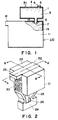
- Figure 1 is a sectional view of an example of an ink refilling system according to an embodiment of the present invention.
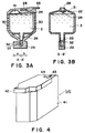
- Figure 2 is a perspective view of an example of an ink refilling container.
- Figure 3A and Figure 3B are sectional views of an ink refilling container.
- Figure 4 is a perspective view of an ink cartridge.
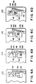
- FIGS 5A, 5B and 5C illustrate ink refilling steps.
- Figures 6A, 6B, 6C and 6D illustrate ink refilling steps particularly at the ink injection port.
- Figures 7A, 7B and 7C illustrate ink refilling steps using an adopter, particularly in the operation of a lever of the adopter.
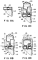
- FIGS. 8A, 8B, 8C and 8D illustrate ink refilling steps according to another embodiment of the present invention.
- Figure 9A and 9B are perspective views of a casing for the ink cartridge, an adopter and an ink refilling container.
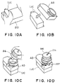
- Figure 10A to 10D depict the manipulation of a further embodiment of an ink refilling container.
- the ink refilling container or ink refiller R1 comprises an ink containing portion 1 for containing ink 3 and a cover covering the ink container 1, an ink injection tube 6 for injecting the ink from the ink containing portion 1 to the ink container 11.
- the cover 2 is provided with an air vent 4 for communication with the ambient air and the inside of the ink containing portion 1.
- the air vent 6 is sealed by a sealing member 5 which seals the air vent when the ink refiller R1 is not used, but the sealing member 5 is removed when the refilling operation is to be effected.
- the cover 2 is mounted to the ink containing portion 1 by ultrasonic welding.
- the ink jet Cartridge IJC comprises an ink container 11 for containing the ink, and a recording head 12 for ejecting ink supplied from the ink container.
- an ink absorbing material 12 is accommodated, and an air vent 14 for communication between the inside of the ink container 11 and the ambience.
- the ink refiller R1 is connected with the ink jet cartridge IJC through the air vent 14.
- the communication may be established through an opening exclusively for the connection.
- the injection tube 6 of the ink refiller R1 connected to the ink jet cartridge IJC is brought into press-contacted with the absorbing material 13 to permit smooth flow out of the ink from the supply port 6 at the end of the ink injection tube 6 to the inside of the ink container 11.
- the ink containing portion 11 of the ink refiller R1 is made of rigid material, so that it is not easily deformed by external force. Therefore, the ink refiller R1 is easy to manipulate. On the contrary the cover 2 is deformable by external force so as to permit the ink containing portion 1 to be pressurized.
- the air vent 4 is closed by the sealing member 5, and therefore, the ink forms a meniscus at the supply port 7 of the ink injection tube 6, thus preventing leakage of the ink therethrough.
- the supply port 7 has such a diameter that the meniscus is formed at the supply port 7 when the air vent 7 is closed, and that the meniscus not easily destroyed by external factor such as force.
- the preferable diameter is determined properly by one skilled in the art depending on the material of the ink and the viscosity thereof. Generally, it is preferably 1 mm - 3 mm.
- the sealing member 5 is removed from the air vent 6 to permit communication with the ambience. Then, the air is introduced thereinto through the air vent 4, and the meniscus formed at the supply port 7 of the ink injection tube 6 moves to be brought into contact with the absorbing material 13 in the ink container, so that the ink refilling into the ink container 11 is started.
- the ink full speed into the absorbing material 13 is controlled by the ink absorbing material inherent to the absorbing material 13 because the end of the ink injection tube is in close contact with the absorbing material, and therefore, the ink does not leak out during the refilling operation.
- the connecting portion between the ink container 11 and the ink refiller R1 is hermetically sealed, and the air in the ink container 11 is gradually removed from a part other than the connecting portion.
- the air is removed gradually from the recording head 12.
- This structure is advantageous because the air is removed through the recording head, the ink flowed into the absorbing material is directed toward the recording head, thus permitting proper filling of the ink adjacent the recording head.
- another connecting port other than the air vent 14 is provided to permit removal of the air through the air vent 14, without using the air vent 14 of the ink container for the connection for the ink supply.
- the refilling process First, if the end of the ink injecting tube 6 of the ink refiller R1 is plugged for the purpose of preventing the ink leakage, the cap is removed. Subsequently, the ink injection tube 6 is inserted into the used-up ink container 11 through the air vent 14. With this state, the ink injecting tube 6 is pressed into the ink absorbing material 13, and the ink refilling operation is not carried out.
- the cover 2 of the ink refiller R1 is pushed toward the inside of the ink containing portion 1, by which the meniscus of the ink at the end of the ink injection tube 7 is advanced to establish communicating state between the absorbing material 13 and the ink in the ink refiller R1.
- the sealing member 5 is removed from the air vent 4 of the cover 2 to release the inside of the ink containing portion 1 to the ambience.
- the ink supply tube 6 is directed downwardly to permit spontaneous falling of the ink from the ink refiller R1, as shown in Figure 1. Before the sealing member 5 is removed, the state of Figure 1 may be established.
- the sealing member 5 is removed to open the inside of the ink containing portion 1 to the ambience, by which the ink refilling action starts by the gravity.
- the spontaneous falling of the ink is used.
- the ink absorbing material in the ink container 11 is made of polyether polyurethane foam or the like is used, and therefore, when the ink is to be injected for the first timer it is required to reduce the pressure or to forcedly wet it with the ink by squeezing it within the ink, or the like.
- the absorbing material 13 has been once wetted with the ink, and therefore, the surface of the foamed material is wet with the dye of the ink. Since the dye is easily solved in the ink solvent, and therefore, it has high affinity with the fresh ink upon the refilling.
- the ink can be spontaneously falls into the material. If the residual ink deposited on the absorbing material 13 has been dried, and therefore, the ink does not easily fall, the cover 2 of the refiller R1 is pushed, by which the ink is pressed into the ink containing portion 1 to trigger the ink falling action.
- the ink is filled in accordance with the ink absorbing speed of the absorbing material 13 in the ink container.
- the ink injection tube 6 and the air vent 14 are closely contacted, and/or the ink injection tube is press-contacted to the absorbing material.
- the ink is not forced beyond the ink absorbing speed, and therefore, the liability of the ink leakage can be effectively prevented.
- the ink absorbing speed of the ink absorbing material 13 is influenced by the material, the degree of dryness of the ink absorbing material upon the ink refilling operation. Generally, however, it is not less than 40 sec/10 -6 m 3 sec/cc. Therefore, by properly machining the inside shape or surface of the ink injection tube, the ink flow-out speed may be made not less than 40 sec/10 -6 m 3 (sec/cc).
- Figures 2 - 7 show ink refilling container and ink refilling method using the container according to other embodiments of the present invention.
- Figure 2 there is shown an ink refiller in a perspective view
- Figure 3 is a sectional view thereof
- Figure 4 shows an ink jet cartridge having a closable injection port for the ink refilling
- Figures 5, 6 and 7 show operation steps and relative relationship between the ink refiller and the ink jet cartridge upon ink refilling operation.
- Figures 2 and 3 show an ink refiller R2.
- Figure 3A is a sectional view taken along a line A-A in Figure 2
- Figure 3B is a sectional view taken along a line B-B' of Figure 3.
- the ink refiller R2 comprise an ink containing portion 21, a cap band 28, a covering member 22 for covering in the ink containing portion 21.
- the ink containing portion 21 is closed by the covering meter 22, and the injection tube 26 is provided at the opposite side therefrom.
- the cap band 28 is provided with a hook-like cap (cap) 29, an elastic portion 30, a releasing lever 25, a pressurizing chamber 31 and an air vent 24.
- the cap 29 and the injection tube are fixed by a lock mechanism 33.
- FIG 4 is a perspective view of an ink jet cartridge to be refilled.
- Figure 5 illustrates the mounting operation for mounting the ink refiller R2 to the ink cartridge.
- Figure 6 illustrates the mounting.
- an ink cartridge is provided with an air vent 44.
- a movable communication port 44 air vent
- injection port 45 Below it, the ink absorbing material 13 is closely contacted.
- the movable communication port 44 is fixed by the movable communication port locking mechanism 50 and a movable communication port stopper 48.
- Adjacent the hole 43 of the communication port 44 there are provided a wedge 46 for removing the cap, a cap stopper A47 and a cap stopper B49.
- the cap 29 With the deviating action, the cap 29 is abutted to the cap stopper B49 while being pushed by the wedge 46 for removing the cap, and as shown in Figure 6C, it is engaged with the cap stopper A47. At this time, the movable communication port locking mechanism 50 is released by being pushed by the cap 29. As shown in Figure 6C, the movable communication port 44 becomes movable. With further deviating motion of the ink refiller R2, the cap 29 is away from the injection tube 26, by which the injection tube 26 pushes the communication port 44 so as to reach the end portion of the hole 43, as shown in Figure 6D. With this state, the injection tube 26 is insertable into the injection port 45.
- the elastic portion 30 functions to absorb the stretching of the cap 29 by the cap stopper A47.
- the cap 29 is away from the injection tube 26, by which the manipulation with short stroke is enabled.
- the movable communication port 44 is opened immediately before the refilling action by the injection port 26, so that the ink tank is free of the influence of the ambience, and the ink leakage from the ink container is prevented even if it is fallen down.
- the movable communication port 44 is moved by the injection tube 26, and is inserted into the injection port 24. Thereafter, while confining the pressurizing chamber 31 of the refiller R2 by one hand, as shown in Figure 5C, (4), and the releasing lever 25 is released by another hand in a direction (5) in Figure 5C, by which the air vent 24 is released to permit spontaneous falling of the ink 3 through the injection tube 26. Therefore, there is hardly any possibility of the ink leakage from the ink refiller R2. At this time, the locking cut-away portion 33 of the injection tube 26 is engaged with the injection port 45 to prevent removal of the ink refiller. After this point, the assured refilling action continues with nothing done by the operator.
- the operations are carried out in the opposite directions.
- the releasing lever 25 is restored to close the air vent 24. By doing so, the ink does not leak even if some remains therein.
- the ink refiller R2 is lifted. In this state, it is not removed because of the engagement with the cap 29.
- the ink refiller R2 is deviated to the key hole 43.
- the cap 29 is engaged with the cap stopper A47, and therefore, the injection tube 26 is accommodated in the cap 29.
- the movable communication port 44 is restored to be placed above the injection port 45.
- the ink refiller R2 is moved further from the hole 43 until the cap 4 is removed.
- the ink refiller R2 is removed from the ink cartridge IJC. This is the end of the operations.
- the movable communication port 44 is above the injection port 45, and therefore, the ink does not leak even if the ink jet cartridge falls dawn, erroneously.
- the operator manually connects the ink refilling container and the ink jet cartridge, and effect the refilling operation.
- the operator's hands may be contaminated with the ink.
- an adopter may be used, through which the ink refiller container is set to the ink jet cartridge, before the refilling operation is started. Then, the problem of the contamination with the ink can be further reduced.
- Figures 7 and 8 shows an example using the adapter.
- the adapter AD is provided with a guiding portion 102 for receiving ink refilling container R3 and an ink jet cartridge engaging member 101 formed into substantially the same outer configuration of the ink jet cartridge IJC.
- the guiding portion 102 is formed at a position faced to an opening for ink reception of the ink cartridge (air vent in this embodiment).
- the guiding portion 102 is provided with a rotatable member 110 rotating about a shaft 106 by operation of a lever 107, and the rotatable member 110 is provided with two pins 104 and 105, and an opening 108.
- the pin 104 moves the cap of the ink refilling container R3 in the guiding portion 102 to be removed from the ink injection tube.
- the pin 105 functions to remove the cap into the ink injection tube after the completion of the refilling operation.
- the movable communication port 44 formed at the air vent portion of the ink jet cartridge IJC is moved by the guide 104 to face the air communication port (injection port) toward the outside.
- the ink jet cartridge IJC is provided with a movable communication port 44 at the portion of the air vent 45 and a hole 43.
- the pin 104 of the adopter AD is inserted into the hole 43 then the adopter AD is mounted to the ink cartridge IJC.
- lever 107 is moved about the shaft 105 in a direction A, and then, a locking cut-away portion 109 of the injection tube 26 is engaged with a lever 107, as shown in Figure 8D to prevent removal of the refiller R3. Therefore, the refilling action is assured without operator's manipulation.
- the elastic portion 30 is effective to absorb the tension of the cap in engagement with the pin 104 and the lever 107.
- the cap 29 is disengaged from the injection tube 26.
- the hole 108 of the lever 107 functions as a stopper to prevent insertion without removal of the cap 29 is prevented.
- the lever 107 the movable communication port 44 is opened immediately before the refilling operation, thus preventing ink leakage by the influence of the ambience or by erroneously falling it down.
- the injection tube 26 involves air, and therefore, a meniscus 32 is formed by the surface tension of the ink 3, so that the ink does not fall.
- the pressurizing chamber 31 is pushed by one hand, by which the meniscus 32 is broken to permit spontaneous falling.
- the refilling container R3 has already be inserted into the injection port, and therefore, the ink is not liable to leak.
- the inside diameter of the injection port 45 is made larger than the outer diameter of the injection tube, by which the air is easily removed from the ink jet cartridge IJC during the refilling operation.
- the releasing lever 25 is returned to close the air vent 24, so that the ink leakage is prevented even if the ink remains therein.
- the lever 107 is returned slightly from the cut-away portion 109, and the refiller R3 is lifted to such an extent that the lever 107 is movable.
- the lever 107 is returned completely then, and the refiller R3 is lifted.
- the cap 29 is engaged with the returning pin 105, and therefore, the injection tube is stopped, and simultaneously, the movable communication port 44 is returned to close the injection port 45.
- the refiller container R3 is removed from the adopter AD. Finally, the adopter AD is removed. When the refiller R3 is removed in this manner, the movable communication port 44 is already closed, and therefore, the ink does not leak even if it falls down erroneously.
- the adopter AD and the ink refiller R3 are on sale together with the ink jet cartridge IJC, for the users convenience.
- the service life of the recording head of the ink jet cartridge IJC is sufficiently longer as compared with the quantity of the ink contained in the ink container.
- the ink refilling operation can not be repeated a great number of times, since then the recording head would be broken with the result of improper printing.
- the casing 203 comprises a top casing 200 and a bottom casing 201 connected with each other by a hinge 202, so that it is openable.
- the lower casing 201 contains one ink jet cartridge IJC, one adopter AD, and four ink refiller.
- the ink cartridge can be used 5 times, including the ink already contained in the ink cartridge.
- the ink jet cartridge IJC is fed at a predetermined position in the bottom case 201, as shown in Figure 10A.
- the refiller R4 and adopter AD are omitted for the sake of simplicity.
- the adopter AD is set to the ink jet cartridge IJC
- the refiller R4 is set to the adopter AD.
- the lever 107 is moved to insert the refiller R4 into the ink jet cartridge IJC.
- an air vent 204 is broken as shown in Figure 10D at a top of the refiller R4.
- the air vent 204 is easily broken, and therefore, the refilling container R4 can be produced at very low cost.
- the operation is possible on the bottom case 201 of the container, and therefore, the deposition of the ink to the neighborhood can be avoided. If an ink absorbing material sheet is placed below the bottom case 201, the contamination with the ink is not a concern.
- the nozzle of the ink cartridge is not damaged. Since the ink refilling container R4 is contained between the bottom case 201 and the top case 200, and therefore, the evaporation of the ink from the refilling container R4 can be prevented.
- the adopter AD is used, but the adopter AD may not be used, and the refilling manipulation is possible using the casing, similarly.
- EP0509747A1 or the like discloses that the remaining quantity of the ink in the ink jet recording cartridge is detected by two detecting pins inserted into the ink absorbing material in the ink cartridge. When the remaining quantity of the ink reduces to a predetermined degree so that the resistance between the detecting pins reduces to a predetermined degree, by which it is detected that a predetermined amount of the ink remains.
- the refilling container contains a predetermined quantity of the ink in view of the detected remaining quantity of the ink, and all of the ink in the refilling container is loaded. By doing so, the refilling operation can be repeated without overflow of the ink.
- an addicted ink refilling container is set to the ink cartridge having an addicted movable communication port, and therefore, the ink can be easily reloaded into the used ink cartridge without color mixture and with small time period requiring users attention. Since the injection port is movable communication port, and therefore, the ink evaporation through the injection port can be minimized. In addition, by using it with the assured detection of the ink remaining quantity, the overflow of the ink can be prevented. In addition, there is hardly any compressible portion, and therefore, the ink does not leak even if it falls. In addition, the reloading can be effected with addicted ink, and therefore, the nozzle or the like is not damaged. Moreover, the ink refilling container and the ink cartridge may have the same parts as in the conventional ones, and therefore, the running cost is low.
Description
Claims (13)
- An ink refilling container (R1; R2; R3; R4) comprising:an ink containing portion (1; 21) for containing an ink (3) to refill,an ink injection tube (6; 26) for connection with said ink containing portion (1; 21),an ink (3) for refilling, andan air vent (4; 24), provided in said ink refilling container (R1, R2; R3; R4), for communication with ambience,
characterized byan openable member (5; 25) for closing said air vent (4; 24),
whereina meniscus (32) of ink (3) is formed adjacent an end of said injection tube (6; 26), andthe ink (3) is not leaked externally as long as said air vent (4; 24) is closed. - A container according to claim 1, wherein an inside diameter of said ink injection tube (6; 26) is 1 - 3 mm.
- A container according to claim 1, wherein a capping member (29) is provided at an end of said ink injection tube (6; 26).
- A container according to claim 1, wherein said ink containing portion (1; 21) comprises a container body and a cover (2; 22), and the cover (2; 22) has elasticy.
- A container according to claim 3, wherein said ink injection tube (6; 26) is deviated in one direction relative to the capping member (29).
- A combination comprising an ink container (R1; R2; R3; R4) according to claim 1 and an adopter (AD).
- An ink refilling method in which an ink (3) is refilled into an ink jet cartridge (IJC) having a recording head (12) and an ink container (11; 41) having therein an ink absorbing material (13) for absorbing the ink (3) to be supplied to the recording head (12) comprising the steps ofpreparing an ink refilling container (R1; R2; R3; R4) having an ink containing portion (1; 21) for containing the ink (3) to refill, an ink injection tube (6; 26) for connection with said ink containing portion (1; 21), said refilling container further comprising an air vent (4; 24) for communication with ambience, and an openable member (5; 25) for closing said air vent (4; 24), wherein a meniscus (32) of ink (3) is formed adjacent an end of the injection tube (6; 26) and the ink (3) is not leaked externally as long as the air vent (4; 24) is closed,press-contacting said end of the ink injection tube (6; 26) to the absorbing material (13) in said ink container (11; 41), by which the meniscus (32) of the ink (3) formed in the injection tube (6; 26) is broken, in response to which the ink refilling action starts.
- A method according to claim 7, wherein the break of the meniscus (32) is accomplished by pressing a part of an ink containing portion (1; 21) of said ink refilling container (R1; R2; R3; R4), so that the meniscus (32) is advanced to be brought in contact with the absorbing material (13).
- A method according to claim 7, wherein said ink container (11; 41) of said ink jet cartridge (IJC) is provided with an air vent (14), and the injection tube (6; 26) is inserted into the ink container (11; 41) through the air vent (14), and is press-contacted to the absorbing material (13).
- A method according to claim 9, wherein said air vent of said ink jet cartridge (IJC) comprises a movable communication port (44) and a fixed communication port (45), and wherein the fixed communication port (45) is in contact with the absorbing material (13), and the movable communication port (44) is movable between a position covering the fixed communication port (45) and the position for exposing it.
- A method according to claim 10, wherein said air vent of said ink jet cartridge (IJC) is provided with a groove for receiving said ink injection tube (6; 26), and by moving the ink injection tube (6; 26) along the groove, the movable communication port (44) is moved to expose the fixed communication port (45), and the ink injection tube (6; 26) is inserted into the fixed communication port (45).
- A method according to claim 11, wherein an adopter (AD) is used to effect the operation.
- A method according to claim 7, wherein the ink (3) is refilled using spontaneous falling of the ink.
Applications Claiming Priority (4)
| Application Number | Priority Date | Filing Date | Title |
|---|---|---|---|
| JP1508493 | 1993-01-01 | ||
| JP15084/93 | 1993-01-01 | ||
| JP314793/93 | 1993-12-15 | ||
| JP31479393A JP3222294B2 (en) | 1993-01-01 | 1993-12-15 | Ink refill container and ink refill method using the container |
Publications (3)
| Publication Number | Publication Date |
|---|---|
| EP0611656A2 EP0611656A2 (en) | 1994-08-24 |
| EP0611656A3 EP0611656A3 (en) | 1994-09-21 |
| EP0611656B1 true EP0611656B1 (en) | 1998-03-18 |
Family
ID=26351175
Family Applications (1)
| Application Number | Title | Priority Date | Filing Date |
|---|---|---|---|
| EP93121065A Expired - Lifetime EP0611656B1 (en) | 1993-01-01 | 1993-12-29 | Ink refilling container and ink refilling method using same |
Country Status (4)
| Country | Link |
|---|---|
| US (1) | US6164765A (en) |
| EP (1) | EP0611656B1 (en) |
| JP (1) | JP3222294B2 (en) |
| DE (1) | DE69317543T2 (en) |
Cited By (1)
| Publication number | Priority date | Publication date | Assignee | Title |
|---|---|---|---|---|
| US6474798B1 (en) | 1984-10-11 | 2002-11-05 | Seiko Epson Corporation | Ink supplied printer head and ink container |
Families Citing this family (34)
| Publication number | Priority date | Publication date | Assignee | Title |
|---|---|---|---|---|
| US6145974A (en) * | 1983-10-13 | 2000-11-14 | Seiko Epson Corporation | Ink-supplied printer head and ink container |
| US6276785B1 (en) | 1983-10-13 | 2001-08-21 | Seiko Epson Corporation | Ink-supplied printer head and ink container |
| US6247803B1 (en) | 1983-10-13 | 2001-06-19 | Seiko Epson Corporation | Ink jet recording apparatus and method for replenishing ink in the tank cartridge |
| JP3327046B2 (en) * | 1995-04-21 | 2002-09-24 | セイコーエプソン株式会社 | Ink tank for recording apparatus and ink supply method for ink tank |
| JP3219609B2 (en) * | 1993-11-29 | 2001-10-15 | キヤノン株式会社 | Ink refill device and ink refill method |
| US5742308A (en) * | 1994-03-30 | 1998-04-21 | Hewlett-Packard Company | Ink jet printer cartridge refilling method and apparatus |
| US5531055A (en) * | 1994-04-06 | 1996-07-02 | Nu-Kote International, Inc. | Refill assembly and system for ink-jet printer cartridges |
| US6238042B1 (en) | 1994-09-16 | 2001-05-29 | Seiko Epson Corporation | Ink cartridge for ink jet printer and method of charging ink into said cartridge |
| US5596358A (en) * | 1994-10-31 | 1997-01-21 | Hewlett-Packard Company | Method and apparatus for refilling a print cartridge having a reservoir pressure of less than ambient pressure |
| US5595223A (en) * | 1994-10-21 | 1997-01-21 | Mitsubishi Pencil Corporation Of America | Ink refilling assembly |
| JP3472293B2 (en) * | 1995-01-13 | 2003-12-02 | キヤノン株式会社 | Liquid ejection head |
| JP3450564B2 (en) * | 1995-01-13 | 2003-09-29 | キヤノン株式会社 | Liquid ejection head |
| JPH0929989A (en) * | 1995-07-14 | 1997-02-04 | Canon Inc | Device for detecting presence or absence of ink, ink reserbvoir, kit, recording unit, recording device, and information processing system |
| DE29512003U1 (en) * | 1995-07-25 | 1995-10-05 | Pelikan Produktions Ag | Device for filling liquid into a container |
| DE69624063T2 (en) * | 1995-11-08 | 2003-02-13 | Canon Kk | Dye refill method and apparatus, ink container and ink jet recording apparatus with such a device |
| US5886719A (en) * | 1996-03-14 | 1999-03-23 | Hewlett-Packard Company | Ink valve having a releasable tip for a print cartridge recharge system |
| KR0174668B1 (en) * | 1996-05-22 | 1999-05-15 | 김광호 | Head cartridge of ink jet printer |
| JP3839875B2 (en) * | 1996-07-12 | 2006-11-01 | キヤノン株式会社 | Liquid discharge head, head cartridge, and liquid discharge apparatus |
| JP3832896B2 (en) * | 1996-06-07 | 2006-10-11 | キヤノン株式会社 | Liquid ejection head, head cartridge, liquid ejection apparatus and head kit |
| US5980029A (en) * | 1996-06-28 | 1999-11-09 | Mitsubishi Pencil Corporation Of America | Ink refilling assembly |
| JP4521978B2 (en) * | 2000-11-08 | 2010-08-11 | キヤノン株式会社 | Ink tank, ink jet recording apparatus |
| US6471333B1 (en) * | 2001-04-30 | 2002-10-29 | Hewlett-Packard Company | Method and apparatus for keying ink supply containers |
| US6386691B1 (en) * | 2001-06-05 | 2002-05-14 | Win-Yin Liu | Ink cartridge of a printer facilitating second refilling |
| KR200278474Y1 (en) * | 2002-03-18 | 2002-06-14 | 이용수 | ink refill structure of cartridge for ink jet printer |
| JP3480463B2 (en) * | 2002-03-26 | 2003-12-22 | セイコーエプソン株式会社 | Ink supply pack, ink supply tool, ink supply set for recording apparatus ink tank, and ink supply method for ink tank |
| US6961531B2 (en) * | 2002-10-17 | 2005-11-01 | Hewlett-Packard Development Company, L.P. | Refillable print cartridge and method of refilling |
| US20050225592A1 (en) * | 2004-04-07 | 2005-10-13 | Stratitec Inc. | Inkjet cartridge cleaning devices |
| DE102008025721A1 (en) * | 2008-05-15 | 2009-11-19 | Pelikan Hardcopy Production Ag | Apparatus and method for refilling an ink cartridge for an ink jet printer |
| SG11201602100TA (en) * | 2013-09-18 | 2016-04-28 | Canon Kk | Ink cartridge, and inkjet printer |
| JP6922234B2 (en) * | 2017-01-31 | 2021-08-18 | ブラザー工業株式会社 | Image recording device |
| JP6926493B2 (en) * | 2017-01-31 | 2021-08-25 | ブラザー工業株式会社 | Image recording device |
| JP7247606B2 (en) * | 2019-01-30 | 2023-03-29 | セイコーエプソン株式会社 | Ink supply container |
| JP7305838B2 (en) * | 2019-04-05 | 2023-07-10 | キヤノン株式会社 | Liquid ejector |
| JP7269077B2 (en) * | 2019-04-05 | 2023-05-08 | キヤノン株式会社 | Liquid ejector |
Citations (1)
| Publication number | Priority date | Publication date | Assignee | Title |
|---|---|---|---|---|
| US5162817A (en) * | 1989-01-28 | 1992-11-10 | Canon Kabushiki Kaisha | Ink jet with residual ink detection that compensates for different ink properties |
Family Cites Families (19)
| Publication number | Priority date | Publication date | Assignee | Title |
|---|---|---|---|---|
| US3482258A (en) * | 1968-07-23 | 1969-12-02 | Esterline Corp | Sterile ink supply |
| US3522607A (en) * | 1968-08-09 | 1970-08-04 | Esterline Corp | Constant level inking system |
| SE371902B (en) * | 1973-12-28 | 1974-12-02 | Facit Ab | |
| JPS60204353A (en) * | 1984-03-30 | 1985-10-15 | Canon Inc | Liquid jet recording apparatus |
| JPS639545A (en) * | 1986-07-01 | 1988-01-16 | Canon Inc | Ink-supplying device |
| JPH0533345Y2 (en) * | 1986-08-13 | 1993-08-25 | ||
| US4976556A (en) * | 1989-01-09 | 1990-12-11 | Smith Corona Corporation | Print carrier rack drive |
| JP2575205B2 (en) * | 1989-01-13 | 1997-01-22 | キヤノン株式会社 | Ink tank |
| US4968998A (en) * | 1989-07-26 | 1990-11-06 | Hewlett-Packard Company | Refillable ink jet print system |
| US4967207A (en) * | 1989-07-26 | 1990-10-30 | Hewlett-Packard Company | Ink jet printer with self-regulating refilling system |
| JP2714173B2 (en) * | 1989-09-18 | 1998-02-16 | キヤノン株式会社 | INK STORAGE CONTAINER, INK STORAGE CONTAINER INTEGRATED INKJET HEAD, INK JET RECORDING APPARATUS HAVING THE SAME, AND METHOD OF FILLING POROUS MATERIAL WITH INK |
| GB2249054B (en) * | 1990-07-10 | 1994-10-19 | Canon Kk | Ink tank,ink jet cartridge having the tank,and ink jet recording apparatus having the cartridge |
| US5136305A (en) * | 1990-12-06 | 1992-08-04 | Xerox Corporation | Ink jet printer with ink supply monitoring means |
| JP3164592B2 (en) * | 1991-01-18 | 2001-05-08 | キヤノン株式会社 | Liquid injection system, liquid injection method, and recording liquid tank |
| IT1245065B (en) * | 1991-04-15 | 1994-09-13 | Olivetti & Co Spa | INK DETECTOR DEVICE FOR A LIQUID INK PRINTING ELEMENT |
| US5199470B1 (en) * | 1991-05-17 | 1996-05-14 | Graphic Utilities Inc | Method and apparatus for refilling ink cartridges |
| CA2084708C (en) * | 1991-12-11 | 1997-11-25 | Hiromitsu Hirabayashi | Ink jet recording apparatus and carriage mechanism therefor |
| US5510820A (en) * | 1992-04-22 | 1996-04-23 | Lexmark International, Inc. | Device for ink refill of a reservoir in a print cartridge |
| US5329294A (en) * | 1992-09-24 | 1994-07-12 | Repeat-O-Type Mfg. Co., Inc. | User refillable ink jet cartridge and method for making said cartridge |
-
1993
- 1993-12-15 JP JP31479393A patent/JP3222294B2/en not_active Expired - Fee Related
- 1993-12-28 US US08/174,442 patent/US6164765A/en not_active Expired - Lifetime
- 1993-12-29 EP EP93121065A patent/EP0611656B1/en not_active Expired - Lifetime
- 1993-12-29 DE DE69317543T patent/DE69317543T2/en not_active Expired - Lifetime
Patent Citations (1)
| Publication number | Priority date | Publication date | Assignee | Title |
|---|---|---|---|---|
| US5162817A (en) * | 1989-01-28 | 1992-11-10 | Canon Kabushiki Kaisha | Ink jet with residual ink detection that compensates for different ink properties |
Cited By (1)
| Publication number | Priority date | Publication date | Assignee | Title |
|---|---|---|---|---|
| US6474798B1 (en) | 1984-10-11 | 2002-11-05 | Seiko Epson Corporation | Ink supplied printer head and ink container |
Also Published As
| Publication number | Publication date |
|---|---|
| DE69317543T2 (en) | 1998-08-27 |
| EP0611656A3 (en) | 1994-09-21 |
| US6164765A (en) | 2000-12-26 |
| EP0611656A2 (en) | 1994-08-24 |
| JP3222294B2 (en) | 2001-10-22 |
| JPH06246926A (en) | 1994-09-06 |
| DE69317543D1 (en) | 1998-04-23 |
Similar Documents
| Publication | Publication Date | Title |
|---|---|---|
| EP0611656B1 (en) | Ink refilling container and ink refilling method using same | |
| JP3219609B2 (en) | Ink refill device and ink refill method | |
| US5581287A (en) | Inkjet printer ink cartridge refilling structure | |
| US6733115B2 (en) | Ink-jet pen with two-part lid and techniques for filling | |
| EP0719646B1 (en) | Ink container, ink cartridge, ink jet apparatus, and manufacturing method therefor | |
| EP0773109A2 (en) | Ink refilling method and apparatus, ink container refilled therewith and ink jet apparatus comprising ink refilling apparatus | |
| US5706870A (en) | Kit and method for refilling ink cartridges | |
| EP0661160B1 (en) | Ink jet cartridge and ink jet printer using it | |
| US6640843B2 (en) | Ink refilling apparatus and method for cartridge of ink jet printer | |
| JPH05162333A (en) | Ink tank cartridge | |
| US6145969A (en) | Method for refilling an ink cartridge | |
| WO2005032825A1 (en) | Method for refilling ink into an ink cartridge | |
| KR100199473B1 (en) | Cartridge of inkjet printer | |
| KR100390863B1 (en) | suction instrument for Ink-cartridge and Refill Device | |
| JPH0976525A (en) | Ink tank, production thereof and ink jet recording apparatus | |
| JPH08281964A (en) | Ink supplementing unit for ink cartridge | |
| JPH09174868A (en) | Ink-refilling device | |
| JPH08318965A (en) | Stopper | |
| JPH09277550A (en) | Ink replenishing apparatus | |
| CN113459674B (en) | Liquid replenishing container and liquid replenishing structure | |
| JPH09169119A (en) | Ink jet recording apparatus | |
| JP3219624B2 (en) | Ink refilling device for ink tank for ink recording head | |
| KR100367130B1 (en) | Method and kit for replugging a ink of ink cartridge | |
| JPH09104118A (en) | Ink supply apparatus | |
| KR102066854B1 (en) | Ink refilling apparatus for ink cartridge |
Legal Events
| Date | Code | Title | Description |
|---|---|---|---|
| PUAI | Public reference made under article 153(3) epc to a published international application that has entered the european phase |
Free format text: ORIGINAL CODE: 0009012 |
|
| PUAL | Search report despatched |
Free format text: ORIGINAL CODE: 0009013 |
|
| 17P | Request for examination filed |
Effective date: 19931229 |
|
| AK | Designated contracting states |
Kind code of ref document: A2 Designated state(s): DE FR GB IT |
|
| AK | Designated contracting states |
Kind code of ref document: A3 Designated state(s): DE FR GB IT |
|
| 17Q | First examination report despatched |
Effective date: 19951027 |
|
| GRAG | Despatch of communication of intention to grant |
Free format text: ORIGINAL CODE: EPIDOS AGRA |
|
| GRAG | Despatch of communication of intention to grant |
Free format text: ORIGINAL CODE: EPIDOS AGRA |
|
| GRAH | Despatch of communication of intention to grant a patent |
Free format text: ORIGINAL CODE: EPIDOS IGRA |
|
| GRAH | Despatch of communication of intention to grant a patent |
Free format text: ORIGINAL CODE: EPIDOS IGRA |
|
| GRAA | (expected) grant |
Free format text: ORIGINAL CODE: 0009210 |
|
| AK | Designated contracting states |
Kind code of ref document: B1 Designated state(s): DE FR GB IT |
|
| ITF | It: translation for a ep patent filed |
Owner name: SOCIETA' ITALIANA BREVETTI S.P.A. |
|
| REF | Corresponds to: |
Ref document number: 69317543 Country of ref document: DE Date of ref document: 19980423 |
|
| ET | Fr: translation filed | ||
| PLBE | No opposition filed within time limit |
Free format text: ORIGINAL CODE: 0009261 |
|
| STAA | Information on the status of an ep patent application or granted ep patent |
Free format text: STATUS: NO OPPOSITION FILED WITHIN TIME LIMIT |
|
| 26N | No opposition filed | ||
| REG | Reference to a national code |
Ref country code: GB Ref legal event code: IF02 |
|
| PGFP | Annual fee paid to national office [announced via postgrant information from national office to epo] |
Ref country code: IT Payment date: 20101217 Year of fee payment: 18 Ref country code: GB Payment date: 20101223 Year of fee payment: 18 |
|
| PGFP | Annual fee paid to national office [announced via postgrant information from national office to epo] |
Ref country code: DE Payment date: 20101231 Year of fee payment: 18 |
|
| PGFP | Annual fee paid to national office [announced via postgrant information from national office to epo] |
Ref country code: FR Payment date: 20120103 Year of fee payment: 19 |
|
| GBPC | Gb: european patent ceased through non-payment of renewal fee |
Effective date: 20121229 |
|
| REG | Reference to a national code |
Ref country code: FR Ref legal event code: ST Effective date: 20130830 |
|
| PG25 | Lapsed in a contracting state [announced via postgrant information from national office to epo] |
Ref country code: DE Free format text: LAPSE BECAUSE OF NON-PAYMENT OF DUE FEES Effective date: 20130702 |
|
| REG | Reference to a national code |
Ref country code: DE Ref legal event code: R119 Ref document number: 69317543 Country of ref document: DE Effective date: 20130702 |
|
| PG25 | Lapsed in a contracting state [announced via postgrant information from national office to epo] |
Ref country code: GB Free format text: LAPSE BECAUSE OF NON-PAYMENT OF DUE FEES Effective date: 20121229 Ref country code: FR Free format text: LAPSE BECAUSE OF NON-PAYMENT OF DUE FEES Effective date: 20130102 |
|
| PG25 | Lapsed in a contracting state [announced via postgrant information from national office to epo] |
Ref country code: IT Free format text: LAPSE BECAUSE OF NON-PAYMENT OF DUE FEES Effective date: 20121229 |