EP0611143A2 - Einrichtung und Verfahren zur Steuerung der Einführung von chemischem Schaummittel im Wasserstrom bei Feuerbekämpfung - Google Patents
Einrichtung und Verfahren zur Steuerung der Einführung von chemischem Schaummittel im Wasserstrom bei Feuerbekämpfung Download PDFInfo
- Publication number
- EP0611143A2 EP0611143A2 EP94300932A EP94300932A EP0611143A2 EP 0611143 A2 EP0611143 A2 EP 0611143A2 EP 94300932 A EP94300932 A EP 94300932A EP 94300932 A EP94300932 A EP 94300932A EP 0611143 A2 EP0611143 A2 EP 0611143A2
- Authority
- EP
- European Patent Office
- Prior art keywords
- motor
- speed
- signal
- pump
- water
- Prior art date
- Legal status (The legal status is an assumption and is not a legal conclusion. Google has not performed a legal analysis and makes no representation as to the accuracy of the status listed.)
- Granted
Links
Images


Classifications
-
- G—PHYSICS
- G05—CONTROLLING; REGULATING
- G05D—SYSTEMS FOR CONTROLLING OR REGULATING NON-ELECTRIC VARIABLES
- G05D11/00—Control of flow ratio
- G05D11/02—Controlling ratio of two or more flows of fluid or fluent material
- G05D11/13—Controlling ratio of two or more flows of fluid or fluent material characterised by the use of electric means
- G05D11/131—Controlling ratio of two or more flows of fluid or fluent material characterised by the use of electric means by measuring the values related to the quantity of the individual components
-
- A—HUMAN NECESSITIES
- A62—LIFE-SAVING; FIRE-FIGHTING
- A62C—FIRE-FIGHTING
- A62C5/00—Making of fire-extinguishing materials immediately before use
- A62C5/02—Making of fire-extinguishing materials immediately before use of foam
-
- Y—GENERAL TAGGING OF NEW TECHNOLOGICAL DEVELOPMENTS; GENERAL TAGGING OF CROSS-SECTIONAL TECHNOLOGIES SPANNING OVER SEVERAL SECTIONS OF THE IPC; TECHNICAL SUBJECTS COVERED BY FORMER USPC CROSS-REFERENCE ART COLLECTIONS [XRACs] AND DIGESTS
- Y10—TECHNICAL SUBJECTS COVERED BY FORMER USPC
- Y10S—TECHNICAL SUBJECTS COVERED BY FORMER USPC CROSS-REFERENCE ART COLLECTIONS [XRACs] AND DIGESTS
- Y10S261/00—Gas and liquid contact apparatus
- Y10S261/26—Foam
Definitions
- This invention relates generally to a fire extinguishing system in which a calculated quantity of a liquid chemical foamant is introduced into the main water stream being directed at a fire, and more particularly to a microprocessor-based control system for such equipment in which the chemical foamant is introduced into the fluid into the water stream by a positive displacement pump driven by a DC motor that is energized by a pulse width modulated signal over a first range of speeds and by a fixed-width burst-modulated pulse width modulated signal over a second range of speeds.
- That system generally comprises a water supply arranged to deliver water at varying flow rates through a hose. Associated with the hose is a flow meter which produces an electrical signal proportional to the rate of water flow through the hose.
- the chemical foamant is contained within a supply tank and a positive displacement piston pump having an adjustable piston stroke is driven by a variable speed electric motor for pumping the chemical foamant from the supply tank into the water stream passing through the hose.
- a microprocessor-based controller receives the electrical signal from the flow meter as well as another signal proportional to pump speed and then computes the rate at which the electric motor driving the pump should be driven to introduce a metered quantity of the chemical foamant into the hose such that the percentage concentration of the foamant in the water remains at a preset value even though the water flow through the hose varies.
- Class A Foam is from five to ten times more effective as a fire suppressant than water alone. Utilizing foam, fires are extinguished faster and with substantially less water damage. Foam can be an effective barrier preventing fire from spreading and protecting adjacent structures.
- the chemical foamant is not inexpensive. It is, therefore, desirable to have a foam injection system capable of automatically proportioning the foam in an exact concentration required for the specific fire-fighting problem, but without overusing and therefore wasting the chemical foamant.
- a positive displacement pump is used to inject the concentrate into the water stream, precise control must be maintained over the pump speed as the water flow varies if a preprogrammed concentration of liquid chemical foamant to water is to be maintained.
- the motor driving the pump must have its speed controlled over a wide range, say, from 2600 rpm down to 400 rpm.
- a DC motor is used to drive the pump and the speed of the motor is controlled over a first predetermined range using pulse width modulation of the DC signal driving the motor.
- the motor will thus operate at full rated speed when the duty cycle of the pulse width modulated drive signal is 100 percent. It has been found, however, that the motor when driving the multi-cylinder, positive displacement pump load tends to stall when the duty cycle of the pulse width modulated drive signal approaches about 30 percent. This corresponds to a 3:1 duty cycle ratio which translates to a speed ratio of about 12:1. This is too small a range to adequately proportion the chemical foamant into the water stream to maintain the desired proportion over the full range of flow rates.
- accommodation was made by having a pump whose stroke volume can be varied. The mechanism used to vary the stroke volume, however, was difficult to adjust during normal operation of the foam proportioning system.
- the present invention obviates this problem by effectively extending the speed ratio of the pump from about 12:1 to about 200:1.
- Another object of the invention is to provide a control arrangement which greatly extends the speed range of the pump, making it unnecessary to adjust the pump's stroke volume to cover the desired range of flow rates encountered during the use of fire-fighting systems.
- the fire-fighting system constructed in accordance with the present invention is of the type that includes a water supply means for normally delivering water at varying flow rates through a hose member, there being a flow meter device in the hose member for producing an electrical signal related to the rate of water flow through the hose.
- a liquid foam concentrate is provided in a supply tank and a positive displacement pump is arranged to pump the liquid chemical foamant concentrate from the tank and inject it into the hose member. The speed of the pump is sensed and fed back to a microprocessor-based controller connected to receive the electrical signal related to flow and that related to pump speed.
- the microprocessor determines the speed at which the motor should be driven to introduce a metered quantity of the chemical foamant concentrate into the water stream passing through the hose which depends on the rate of flow of water through the hose.
- the output of the microprocessor-based controller is then fed to the pump drive motor in the form of a pulse-width modulated signal of a predetermined frequency whose duty cycle is determined by the computing means for varying the speed of the drive motor between a maximum corresponding to a 100% duty cycle and a lower intermediate speed which is slightly above the motor's stall speed.
- the low duty cycle pulse width modulated motor control signal is further burst width modulated so that the pulse width modulated signal is turned on and off at predetermined time intervals determined by the microprocessor for varying the speed allowed of the driven motor between the lower intermediate speed allowed by pulse width modulation and a predetermined minimum (intermittent stepped) speed whereby the flow rate of the liquid foam concentrate into the hose member is controllable over an extended range.
- the fire-fighting system of the present invention is illustrated schematically in Figure 1 and is seen to include a conventional water pump 10 normally found on existing fire trucks. It is adapted to have its inlet 12 connected to a raw water supply and delivers water under pressure through a manifold 14 and a hose 76 having a variable flow nozzle 78 at its discharge end. Appropriately mounted in a fitting 16 associated with the manifold 14 is a flow meter 18 which delivers electrical signals over conductor 20 to a pulse forming circuit 22. The rate at which the pulse forming circuit 22 outputs pulses on conductor 24 is indicative of the volume rate of flow of water through the hose 14.
- the flow meter output signal is applied to a microprocessor-based controller contained within a computer and display module 26, only the face plate 28 of which can be seen in the view of Figure 1. Visible on the face plate 28 is a display panel 30 which may typically comprise a five digit, 7-segment display of conventional design. Associated with each of a series of words stencilled on the face plate are discrete LED's identified by numeral 31. By this means, a particular operating mode can be identified by an illuminated one of the LEDs.
- Push-button 32 is a labeled on/off and is used to determine whether foam concentrate is to be injected into the water stream or not.
- Push-button 34 when repeatedly depressed and released causes a number of different functions to be displayed on the five-digit display screen 30. More particularly, the display may be made to operate so as to indicate whether the foam inject is on or off, the flow-per-minute of water or foam solution, the total amount of water or foam solution pumped subsequent to an earlier reset, the foam concentration injection rate setting in percent and the total amount of foam concentrate pumped. The value of concentrate pumped will be in the same unit of measurement as the water flow.
- Push-button 36 is a down arrow and when depressed, functions to decrease the value of the quantity then being displayed.
- push-button 38 is an up arrow and is used to increase the quantity then being presented on the display.
- Another push-button is hidden from view behind a removable screw and is used to place the system in a setup or calibrate mode.
- the circuitry in the display module is connected, via a five conductor cable 40 and an optional interlock module 41 to a motor driver circuit 42.
- a motor driver circuit 42 When an air compressor as at 43 is employed to inject air into the nozzle to enhance the range of travel of the foam mixture being sprayed, it is essential that chemical foamant be present in the water stream.
- the interlock 41 functions to shut off the air compressor 43 in the event that the supply of chemical foamant concentrate is low or the pump used to inject it into the water stream is not functional. If compressed air is not used, the module 41 can be omitted, as will be explained with greater particularity below.
- the motor driver circuit is arranged to be energized from the fire truck's 12 volt battery supply 44 having a storage capacitor 46 connected in parallel with it. Because the motor driver 42 in combination with the microprocessor-based controller comprise the heart of the present invention, the circuitry for implementing those devices will be explained in greater detail. Suffice it for now to say that in addition to the control received from the microprocessor controller display module, via cable 40, the motor driver 42 also receives a signal on line 48 indicative of the fact that the level of the foam concentrate in the foam tank 50 has fallen to a predetermined low level as determined by a float sensor 52. It also receives pulses on line 54 coming from a magnetic pickup 56 associated with a notched wheel 58 coupled to the drive shaft 60 of a positive displacement pump 62.
- the positive displacement pump 62 has its inlet 64 connected by a hose 66 to the foam tank and its outlet 68 is coupled by a hose 70 and a check valve 72 to an injector 74.
- the pump when the pump is driven, it is effective to withdraw the foam concentrate from the tank 50 and inject it into the manifold 14 through which the raw water is pumped before exiting through one or more hoses 76 and ultimately out the nozzle 78.
- the drive shaft 60 of the pump 62 is arranged to be driven by a DC motor 80 which receives its energization from the motor driver circuit 42 via diode block 82.
- the speed of the motor 80 is controlled using a pulse width modulated drive signal.
- the average current delivered to the motor is directly proportional to the duty cycle of the pulses used to drive the motor. Since the motor speed is directly related to the average motor current, by varying the duty cycle of the energization pulses, the effective rate of rotation of the pump shaft can be controlled.
- FIG. 2 there is depicted a series of pulse width modulated waveforms of differing duty cycle labeled 100 percent, 50 percent and 30 percent.
- the pulse repetition rate used in the system of the present invention was chosen to be 476 Hz, but limitation to that frequency is not to be inferred.
- the average motor current may be the full rated current, but with a 50 percent duty cycle, the average motor current will only be one-half of the rated value.
- the average motor current will be approximately 30 percent of its full rated value.
- system of the present invention is a flow-based proportioning system that measures water flow and then operates to inject the appropriate amount of foam concentrate to maintain a pre-set percentage, a speed range, greater than that which can be achieved using pulse width modulation control only, is required.
- burst width modulation is used in conjunction with the pulse width modulated motor drive signal.
- the pump speed may be, for example, 1,800 rpm. As the duty cycle decreases from its 100 percent value to the 30 percent value, the speed likewise decreases.
- the microprocessor On reaching the minimum duty cycle value attainable using pulse width modulation, the microprocessor begins switching the 475 Hz 30 percent pulse width modulated signal on and off at a rate which will permit the motor, and therefore the positive displacement pump which it drives, to be driven intermittently with the degree of rotation being determined by the amount of time that the 30 percent duty cycle 476 Hz signal is on during a predetermined time interval.
- the system of the present invention is capable of maintaining a desired concentration of liquid chemical foamant in the water stream over a wide range of flows from, say, 2,000 gallons per minute down to 10 gallons per minute.
- Figure 3 is another graph which is helpful in explaining the motor control algorithm embodied in the present invention.
- the microprocessor is programmed to insure that it will operate in a "SOFT-START" mode where the duty cycle of the pulse width modulated drive is at about 30 percent at start-up.
- the microprocessor continuously samples pump speed and water flow rate and performs a computation to determine what the duty cycle should be in order for the pump to deliver chemical foamant to the line in an amount which will insure a preset concentration of chemical foamant in the water. With high flow rates, the duty cycle will be greater than 30 percent, such that the motor speed is proportional to the computed duty cycle.
- the microprocessor causes operation to switch to the burst width modulated mode such that the motor will be driven in step-wise fashion or intermittently.
- the downward sloping curve 84 in Figure 3 is representative of operation in the burst width modulated mode where a 30 percent duty cycle pulse width modulated signal is on 10 percent of the time and off 90 percent of the time during a given interval.
- microprocessor based.controller/display module 26 includes a microprocessor chip 86 which may preferably be a CMOS 8-bit processor sold by Intel Corporation as its Type 80C51FA. Associated with the microprocessor is an address bus 88 and a data bus 90. Appropriately coupled to the address bus and the data bus is a 128K ROM 92 that stores the program information and a non-volatile RAM 94 used to store operands and other parameters entered by the operator at the time of setup and initialization. For example, at the time of start-up, it is necessary to calibrate the flow meter and the pump and this calibration data is typically stored in the non-volatile RAM 94. Then, in the event of system shut-off or power failure, the previously stored contents are not lost.
- an input latch 96 Shown attached to the data bus is an input latch 96 for storing data entered via the keyboard push-buttons 32, 34, 36 and 38 shown in Figure 1. Another input to the latch 96 comes from the float 52 which senses the level of the liquid chemical foam concentrate in the tank 50.
- display drivers including a segment driver 98 and a digit driver 100, are tied to the data bus.
- the outputs from the display segment driver 98 go to a conventional multi-digit, seven-segment display for creating alpha/numeric symbols and words which become visible to the operator.
- the discrete LEDs 31 ( Figure 1) are treated as a sixth digit as far as multiplexing of digit drive signals is concerned.
- the seven-segment display devices are preferably of the aluminum gallium arsenide-type so that they produce a bright illumination capable of being read in direct sunlight.
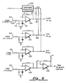
- Figure 6 is a circuit diagram of the pulse shaping circuitry used to receive pulse signals from the flow meter 18, the pump speed sensor 56, 58 and from the float 52 for converting them to a logic level suitable for application to the corresponding inputs to the microprocessor 86 ( Figure 5).
- the DC output voltage from a fire-fighting vehicle is typically about 13.8 volts and it is applied to a switching regulator-type DC-to-DC converter 102 which operates to produce a regulated 5 volt DC signal at its output.
- the signal from the flow meter is applied, via terminal 104 and a current limiting resistor 106, to the inverting input of an operational amplifier 108 that is configured as a comparator.
- a capacitor 110 and a Zenar diode 112 function as a filter while the feedback resistor 114 establishes the threshold for comparison.
- a pull-up resistor 116 is connected between the output line 118 of the circuit such that as the flow meter device produces pulses, they will be converted to digital signals operating between ground and +5 volts.
- the signal input originating at the pump speed sensor is applied to terminal 120 and the op amp circuit 122 conditions the pulsatile signal to one suitable for application to the microprocessor.
- This signal appears on line 124 identified by the acronym PFB standing for "Pump Feed Back".
- the op amp comparator/receiver circuit 126 receives as its input to terminal 128 a signal level shift when the float indicates that the level of liquid foamant in the tank 50 has fallen to a preset threshold. Again, the receiver circuit 126 acts on this signal to produce a binary pulse that is compatible with the microprocessor 86.
- a receiver circuit 130 Located at the bottom of Figure 6 is a receiver circuit 130 that is substantially identical to the receiver circuits previously described. It receives at its input terminal 132 the pulse width modulation (PWM) signal from the microprocessor and conditions that signal, via driver circuit 134, to a signal level compatible with the motor driver circuitry depicted in Figure 7.
- PWM pulse width modulation
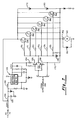
- the motor driver circuitry is comprised of two basic sections, namely, a power supply section, shown enclosed by the broken line box 136, and the MOSFET switching circuit used to apply the motor current to the pump drive motor 80.
- the power supply section 136 is used to boost the 13.8 volt fire truck alternator voltage to a 23 volt signal used to drive the gates on the six parallel connected MOSFET switches 138, 140, 142, 144, 146 and 148.
- the six MOSFET switches are arranged to be driven off and on in unison by a transistor push-pull driver 150.
- the power supply 136 it is necessary for the power supply 136 to boost the DC operating voltage to 23 volts because the motor drive circuit incorporates N channel MOSFETS which require a voltage that is up to 10 volts above the voltage at the low side of the driver block.
- the MOSFET switches are connected between the power source and the motor and when the motor is not energized, terminal 152 to which the motor is connected is at ground potential. When the motor is running, the voltage at terminal 152 is about 12 volts.
- the power supply section 136 comprises a DC-to-DC step-up converter which generates the 23 volt signal which is about 10 volts above the incoming power.
- the up converter 154 When the up converter 154 is turned on, it tends to draw a heavy current such that a current limiting resistor 156 is employed.
- the capacitor 158 connected as shown, functions as a filter.
- the Zenar diode 160 in parallel with that capacitor acts as a transient surge suppressor to protect the circuitry comprising the switching regulator 154.
- the switching regulator functions in a conventional fashion to turn the current flowing through the inductor 162 on and off to thereby generate a voltage proportional to the rate of change of current flowing through the inductor.
- the switching regulator 154 then operates on this voltage to yield a regulated DC voltage of the desired 23 volt amplitude.
- the power supply 136 has its output connected, via a resistor 164, to the collector electrode of a NPN transistor 166, the emitter of which is connected to the emitter of a PNP transistor 168.
- the collector electrode of transistor 168 is connected to the bus 170 leading to the motor input terminal 152.
- the common collectors of the transistors 166 and 168 connect to the gate electrodes of each of the MOSFET switches 138-148, via gate resistors 170-175 which function as current limiters.
- the Zenar diode 176 is included to prevent gate punch through due to inordinately high voltages resulting from electromagnetic interference or the like.
- diodes 178 and 180 are also included to provide a degree of transient protection.
- the PWM signal from the driver 134 is a 12-volt pulse train running at 476 Hz. It is applied, via input resistor 184, to the inverting input of an op amp 186. It is used to drive an optical coupler 188 which effectively isolates the outputs from the phototransistor half of the optical coupler.
- One electrode of the photoemitter half of the optical coupler is connected through a resistor 190 to a 10 volt supply, which includes a Zenar diode 192 having filter capacitors 194 and 196 connected in parallel with it.
- the other electrode of the photo emitter in the optical coupler 184 is tied to the output of op amp 186 and, thus, the isolated output varies in accordance with the PWM signal applied to terminal 182 from the microprocessor.
- the components including capacitor 198 and the diode 200 which are connected between the inverting input of op amp 186 and ground, function as a filter and clamp which operates to clamp the positive excursions at the op amp's input to about 10 volts and the negative excursions to about 0.7 volts.
- the non-inverting input of the op amp 186 is biased at approximately half the power supply voltage by the voltage divider including resistors 202 and 204 of equal ohmic value.
- the feedback resistor 206 is included to prevent oscillation.
- the op amp 186 drives an optical coupler which, in turn, drives the push-button transistors 150 on Figure 7.
- Transistor 166 functions to turn on the MOSFET switches 138 through 148, while transistor 168, when driven into conduction, turns off the MOSFET switches.
- the six MOSFET switches in parallel will share the motor current equally, thus avoiding the overloading of any one switch.
- a notched wheel 58 is affixed to the pump shaft to rotate with it and positioned in close, but non-contact relationship to the wheel 58 is an inductive pickup. As the teeth on the wheel 58 move at some velocity across the pole face of the pickup, a voltage is induced in the device 56 and this signal is applied across the terminals 210 and 212.
- a resistor 214 is connected between the terminal 210 and the non-inverting input of a comparator circuit including op amp 218. Likewise, a resistor 216 is connected in series between input terminal 212 and the inverting input of the op amp 218.
- the resistors 214 and 216 along with the capacitor 220 function as a low-pass filter.
- a resistive voltage divider including resistors 222, 224 and 226 tend to bias the comparator 218 at approximately one-half of the 10 volt supply voltage in that resistors 222 and 226 are made to be of equal ohmic value.
- Capacitors 228 and 230 are included to produce further filtering.
- the two differential inputs 210 and 212 are thus biased a few millivolts apart by a voltage drop across resistor 224.
- the op amp comparator 218 runs open loop and, therefore, the voltage difference required to change the output from one state to another can be quite small.
- the circuit acts as a signal conditioner for adapting the pump feedback (PFB) signal to one that can be applied to the corresponding PFB input of the microprocessor 86 in Figure 5.
- PFB pump feedback
- the system of the present invention is a flow-based proportioning system that continually measures the water flowing through the manifold 14 using a flow meter, such as the paddle wheel-type identified by numeral 16 in Figure 1.
- the foam pump 62 is then operated in a controlled fashion to inject the proportional amount of foam concentrate from the storage tank 50 into the manifold 14 on the discharge side of the pump 10.
- the resulting foam solution is emitted from a standard fog nozzle, an air aspirated nozzle or compressed air foam system (CAFS) equipment by the main fire truck pump 10.
- CAFS compressed air foam system
- the calibration process makes adjustments to the flow meter and the foam pump display readings and can be done using any unit of measurement, i.e., U.S., metric, imperial, etc. The only requirement is that the same unit of measure be used throughout the calibration process to insure proper proportioning by the system.
- Calibration and setup is done using the digital display 30 and the associated push-buttons 32, 34, 36 and 38 as well as a further push-button switch which is normally hidden from view behind a cover screw. Once this screw is removed, access can be had to the push-button switch using a probe that will fit through the threaded opening.
- the calibration mode is entered by depressing this hidden switch. It will cause the display to exhibit "Setup" until one of the other function push-buttons is depressed. The calibration mode is exited by again depressing the hidden switch.
- an accurate flow measuring standard be used to measure the water flow to calibrate the flow meter used in the present system.
- a suitable smooth bore nozzle and an accurate pitot gauge-type instrument may be used. That gauge is used to determine the quantity per minute of water flow normally expected in the use of the system in fighting fires.
- the select button 34 is then depressed and the flow indicating LED will be illuminated. Now, by pressing either the up arrow button 36 or the down arrow button 38, the reading can be set to match the actual flow indicated by the pitot gauge reading.
- the same technique is used to enter the SETUP mode.
- the push-button 34 is then pressed to select the "total foam” entry on the digital display control module 26.
- the calibrate/inject valve 69 is turned to its "calibrate” position and a graduated container is disposed beneath the outlet 71.
- the "ON" button 32 is then depressed, causing the motor 80 to drive the foam pump 62 at a predetermined speed. It will pump the foam concentrate into the measuring container.
- button 32 is again depressed to shut off the pump.
- the up arrow or down arrow buttons 36 or 38 are used to bring the displayed reading equal to the measured quantity.
- the SETUP mode can now be exited by depressing the push-button switch used to initiate the SETUP mode and the cover screw 39 may be replaced. Exiting the SETUP mode causes the calibration constants to be stored in the non-volatile RAM memory 94 ( Figure 5).
- Class A foam is used for most solid combustible materials, including grass, wood, fabric, etc.
- Class B foam is effective in fighting fires involving combustible liquid, such as gasoline, oil, etc.
- the preferred ratio of Class A foam to water is typically about 0.5 percent whereas the ratio for Class B foam is in the range of from 1 to 3 percent.
- the system of the present invention allows simple adjustment of the percentage.
- the "Select” button 34 is repeatedly actuated until the LED 31 associated with the "%" decal on the display face is illuminated. Now, using the up or down arrow buttons 36 and 38, the desired injection rate in percent can be adjusted.
- the microprocessor 86 senses the state of the push-button switches 32, 34, 36 and 38 and updates and refreshes the five-digit, seven-segment display 30 (block 232) and then an internal timer in the microprocessor is sensed to determine if an arbitrarily set time period, e.g., one second, has elapsed (block 234). If not, a test is made to determine if the motor should be operated in the burst mode where the minimum duty cycle (30 percent) PWM signal is to be turned on and off in controlling the low volume injection of foamant into the water stream (block 236).
- the test made at block 236 is to determine if the motor controller is operating at the 30 percent duty cycle PWM at the same time that the maximum chemical foamant is being pumped in matching the preset percentage concentration of foam to water. If not, control loops back to block 232 and the same routine is repeated many times until the one second time interval has been found to have elapsed.
- a test is made to determine if the system is in its "RUN” mode (block 238).
- the flow meter 15 To be in the "RUN” mode, the flow meter 15 must be indicating that water is flowing through the manifold 14 and the float sensor 52 in the foam tank 50 must be indicating that there is foam concentrate in the tank. If these conditions are both met, the microprocessor calculates the maximum amount of foam concentrate that must be added to the then existing water flow rate to meet the previously entered percentage concentration target (block 240).
- a test is made by sensing the speed sensor 56, 58 to determine if the pump is running (block 242). If not, the PWM soft-start sequence is executed (block 244). As mentioned earlier in the specification, to prevent inordinately high motor starting currents, the microprocessor issues a PWM drive control to the motor driver MOSFETS ( Figure 7) so that the minimum (30 percent) duty cycle is used. Control then returns to block 232 and the loop including blocks 232, 234, 236 and the return path 246 is repeated until the one second timer is again satisfied.
- decision block 238 determines that the RUN mode has terminated, usually by the fire-fighter turning off the nozzle valve 78 ( Figure 1). In this event, the pump is stopped (block 250).
- the pump will be driven ON intermittently, at one second intervals, for a calculated length of time less than one second, thereby allowing it to inject foamant at a much lower rate of flow than can be achieved using PWM control alone.
- FIG. 10 is a schematic diagram illustrating the circuitry for implementing the compressed air control module 41.
- the device is arranged "eaves-drop" on the float (FLT) signal and the pump feedback (PFB) signal transferred over the conductors 252 and 254 in the cable 40.
- the signal on the conductor 252 is brought into a receiver circuit 256 which is configured substantially identically to the other receiver circuits already explained and illustrated in Figures 6 and 8. It functions to match the analog float signal to a downstream digital device, in this instance, the one-shot circuit 258.
- the compliment output of the one-shot 258 is diode ANDed with the output from the receiver circuit 256 by the diode AND circuit 260. Hence, if at the time that the one-shot circuit 58 times out and the compliment output goes high, the relay driver transistor 262 will be turned on, provided the output from the receiver circuit 256 is simultaneously high.
- the period of instability of the one-shot is set to be about five seconds.
- the output of the receiver circuit 256 will go high to trigger the one-shot 258 which causes the complimentary output on line 264 to go low.
- the signal out of the receiver 256 on line 266 will be high.
- the transistor 262 will not be turned on unless the signal on line 266 is high when the one-shot times out. This insures that the float switch in the tank is, indeed, firmly indicating a low foam level and is not a momentary dip due to sloshing of the liquid in the tank which might momentarily cause the receiver 256 to output a signal.
- the relay 268 pulls in to reverse the position of the single-pole, double-throw contacts 270.
- the relay contacts are connected in controlling relationship to the air compressor and its associated power supply, neither of which is illustrated.
- the Zenar diodes 272 and 274 function as transient protectors to prevent arcing of the contacts when inductive loads are involved.
- the pump feedback signal PFB is also examined. This signal is only present when and if the pump is being driven in that it is derived from the speed sensor 56, 58.
- the signal on line 254 is appropriately shaped by the receiver circuit 276 whose output on line 278 is applied to the trigger input of a retriggerable one-shot circuit 280.
- the complimentary output of the one-shot 280 is applied to the trigger input of a further one-shot circuit 282.
- the true output of one-shot 280 and that of one-shot 282 are diode ANDed by circuit 284 and the output of that circuit is applied as a trigger input to a third retriggerable one-shot circuit 286.
- the true output of one-shot 286 controls the conduction of the relay driver transistor 288. Since it is an NPN transistor, its base electrode must be high for it to be driven into its conductive state for actuating the relay 290.
- PWM signals for driving the pump occur for a fraction of a second during each one second interval.
- the air compressor 43 should not be shut off just because the motor has intermittently stopped because it is operating in the BURST mode.
- the PFB signal will trigger the one shot 280, causing the input to the diode 292 to go high for a time interval of about three seconds.
- the complimentary output from one shot 280 will, at the same time, trigger the one shot 282 so that the input to the diode 294 will also go high.
- the meta-stable period for one-shot 282 is set to be three seconds.
Applications Claiming Priority (2)
| Application Number | Priority Date | Filing Date | Title |
|---|---|---|---|
| US15003 | 1993-02-09 | ||
| US08/015,003 US5232052A (en) | 1993-02-09 | 1993-02-09 | Apparatus and method for controlling the introduction of chemical foamant into a water stream in fire-fighting equipment |
Publications (3)
| Publication Number | Publication Date |
|---|---|
| EP0611143A2 true EP0611143A2 (de) | 1994-08-17 |
| EP0611143A3 EP0611143A3 (de) | 1994-11-02 |
| EP0611143B1 EP0611143B1 (de) | 1996-09-04 |
Family
ID=21769030
Family Applications (1)
| Application Number | Title | Priority Date | Filing Date |
|---|---|---|---|
| EP94300932A Expired - Lifetime EP0611143B1 (de) | 1993-02-09 | 1994-02-09 | Einrichtung und Verfahren zur Steuerung der Einführung von chemischem Schaummittel im Wasserstrom bei Feuerbekämpfung |
Country Status (7)
| Country | Link |
|---|---|
| US (3) | US5232052A (de) |
| EP (1) | EP0611143B1 (de) |
| JP (1) | JP2620044B2 (de) |
| AU (1) | AU668450B2 (de) |
| CA (1) | CA2115287C (de) |
| DE (1) | DE69400449T2 (de) |
| ES (1) | ES2091089T3 (de) |
Cited By (1)
| Publication number | Priority date | Publication date | Assignee | Title |
|---|---|---|---|---|
| EP3292888A1 (de) * | 2016-09-07 | 2018-03-14 | Albert Ziegler GmbH | Einsatzfahrzeug, insbesondere feuerwehrfahrzeug |
Families Citing this family (86)
| Publication number | Priority date | Publication date | Assignee | Title |
|---|---|---|---|---|
| US6002225A (en) * | 1992-08-20 | 1999-12-14 | Deutsche Thomson-Brandt Gmbh | Method for the control of a motor |
| ATE217689T1 (de) * | 1995-01-11 | 2002-06-15 | Micropump Inc | Anlage mit eingebauter pumpe und fluidströmungsmesser |
| DE19501430A1 (de) * | 1995-01-19 | 1996-07-25 | Marquardt Gmbh | Ansteuerung für einen Elektromotor |
| US5727933A (en) * | 1995-12-20 | 1998-03-17 | Hale Fire Pump Company | Pump and flow sensor combination |
| US5803596A (en) * | 1996-05-17 | 1998-09-08 | Stephens; Patrick J. | Method and apparatus for high capacity production of finished aqueous foam with continuously adjustable proportioning |
| US5764463A (en) * | 1996-09-06 | 1998-06-09 | Hypro Corporation | Current limiting circuit and electronic fuse for use in foam injection fire fighting systems |
| US5765644A (en) * | 1996-09-06 | 1998-06-16 | Hypro Corporation | Dual tank control system and method for use in foam introduction fire fighting systems |
| US6009953A (en) * | 1997-02-25 | 2000-01-04 | Hale Products, Inc. | Foam pump system for firefighting apparatus |
| DE19725521A1 (de) * | 1997-06-17 | 1998-12-24 | Bosch Gmbh Robert | Elektronisch kommutierter Motor |
| US6166500A (en) * | 1997-07-18 | 2000-12-26 | Siemens Canada Limited | Actively controlled regenerative snubber for unipolar brushless DC motors |
| US6047952A (en) | 1998-07-14 | 2000-04-11 | Hale Products, Inc. | Ball valve assembly |
| US6085586A (en) * | 1998-09-24 | 2000-07-11 | Hypro Corporation | Flow meter system with remote displays for each discharge |
| US7184862B2 (en) * | 1999-07-30 | 2007-02-27 | Oshkosh Truck Corporation | Turret targeting system and method for a fire fighting vehicle |
| US7127331B2 (en) * | 1999-07-30 | 2006-10-24 | Oshkosh Truck Corporation | Turret operator interface system and method for a fire fighting vehicle |
| US7107129B2 (en) | 2002-02-28 | 2006-09-12 | Oshkosh Truck Corporation | Turret positioning system and method for a fire fighting vehicle |
| US7729831B2 (en) | 1999-07-30 | 2010-06-01 | Oshkosh Corporation | Concrete placement vehicle control system and method |
| US7162332B2 (en) * | 1999-07-30 | 2007-01-09 | Oshkosh Truck Corporation | Turret deployment system and method for a fire fighting vehicle |
| US6488265B2 (en) | 2000-03-01 | 2002-12-03 | Hale Products, Inc. | Ball valve assembly |
| US6454540B1 (en) | 2000-03-31 | 2002-09-24 | Kovatch Mobile Equipment Corp. | Modular balanced foam flow system |
| US6725940B1 (en) | 2000-05-10 | 2004-04-27 | Pierce Manufacturing Inc. | Foam additive supply system for rescue and fire fighting vehicles |
| US6671459B1 (en) | 2000-06-30 | 2003-12-30 | General Electric Company | DC motor control method and apparatus |
| US6405548B1 (en) | 2000-08-11 | 2002-06-18 | General Electric Company | Method and apparatus for adjusting temperature using air flow |
| US6717383B1 (en) * | 2000-08-30 | 2004-04-06 | Chris S. Brunt | Fountain control for generating dynamically changing flow patterns |
| US6571882B2 (en) * | 2001-01-25 | 2003-06-03 | Ping-Li Yen | Fire fighting vehicle and equipment |
| US7277782B2 (en) | 2001-01-31 | 2007-10-02 | Oshkosh Truck Corporation | Control system and method for electric vehicle |
| US6504338B1 (en) | 2001-07-12 | 2003-01-07 | Varidigm Corporation | Constant CFM control algorithm for an air moving system utilizing a centrifugal blower driven by an induction motor |
| US6733004B2 (en) * | 2002-02-04 | 2004-05-11 | Harry Crawley | Apparatus for generating foam |
| US6741056B1 (en) | 2002-05-15 | 2004-05-25 | Skc, Inc. | Air sampler with compensating pump motor speed |
| US6684959B1 (en) | 2002-08-02 | 2004-02-03 | Pierce Manufacturing Inc. | Foam concentrate proportioning system and methods for rescue and fire fighting vehicles |
| US6973975B1 (en) * | 2002-09-10 | 2005-12-13 | Robwen Inc. | Universal transportable compressed air foam fire fighting system |
| US6766863B2 (en) | 2002-09-20 | 2004-07-27 | Hypro Corporation | Fire fighting foam injection system with auto-start feature |
| US20040055766A1 (en) * | 2002-09-23 | 2004-03-25 | Just-In Case Fire Ltd. | Fire suppression system and method |
| WO2004072485A1 (en) * | 2003-02-05 | 2004-08-26 | Engineered Support Systems, Inc. | Digital pressure controller for pump assembly |
| US6886639B2 (en) * | 2003-08-29 | 2005-05-03 | Hypro Corporation | High flow foam system for fire fighting applications |
| US20050058548A1 (en) * | 2003-09-11 | 2005-03-17 | U.S. Filter/Stranco Products | Method of controlling fluid flow |
| US20050195681A1 (en) * | 2004-02-18 | 2005-09-08 | Henry Gembala | Lightweight concrete mixer |
| US20080035201A1 (en) * | 2005-03-22 | 2008-02-14 | Waterous Corporation | Electronically Controlled Direct Injection Foam Delivery System and Method of Regulating Flow of Foam into Water Stream Based on Conductivity Measure |
| US7878703B2 (en) * | 2004-03-31 | 2011-02-01 | Waterous Company | Electronically controlled direct injection foam delivery system with temperature compensation |
| DE102004032020B4 (de) * | 2004-06-28 | 2006-11-30 | Schmitz Gmbh Feuerwehr- Und Umwelttechnik | Verfahren und Anordnung zur Herstellung von Druckluftschaum zur Brandbekämpfung und Dekontamination |
| US20060032939A1 (en) * | 2004-08-10 | 2006-02-16 | Crash Rescue Equipment Service, Inc. | Fire retardant management system |
| US20080135263A1 (en) * | 2005-02-04 | 2008-06-12 | Graham Douglas Millard | Fire Protection Induction System |
| JP2006229511A (ja) * | 2005-02-17 | 2006-08-31 | Sensatec Co Ltd | 静電容量形近接センサ |
| US7766537B2 (en) * | 2005-02-18 | 2010-08-03 | Henry Gembala | Lightweight foamed concrete mixer |
| DE102005020681A1 (de) * | 2005-04-27 | 2006-11-02 | Saia-Burgess Dresden Gmbh | Verfahren zur Ansteuerung eines Schrittmotors als geräuschreduzierter Ventilstellantrieb |
| US20060243324A1 (en) * | 2005-04-29 | 2006-11-02 | Pierce Manufacturing Inc. | Automatic start additive injection system for fire-fighting vehicles |
| US20070088469A1 (en) * | 2005-10-04 | 2007-04-19 | Oshkosh Truck Corporation | Vehicle control system and method |
| WO2008115220A2 (en) * | 2006-12-19 | 2008-09-25 | Dakotafire Systems, Inc. | Fire suppression gel delivery and truck cab protection systems |
| DE102007055837B4 (de) * | 2007-03-07 | 2011-04-28 | Denso Corporation, Kariya-City | Last-Ansteuerverfahren |
| US20080236846A1 (en) * | 2007-03-23 | 2008-10-02 | Jonathan Gamble | Stationary fire fighting foam system and method |
| US7598683B1 (en) | 2007-07-31 | 2009-10-06 | Lsi Industries, Inc. | Control of light intensity using pulses of a fixed duration and frequency |
| US8604709B2 (en) | 2007-07-31 | 2013-12-10 | Lsi Industries, Inc. | Methods and systems for controlling electrical power to DC loads |
| US8903577B2 (en) | 2009-10-30 | 2014-12-02 | Lsi Industries, Inc. | Traction system for electrically powered vehicles |
| US7703543B2 (en) * | 2007-10-12 | 2010-04-27 | Fm Global Technologies | Fire fighting foam dispensing system and related method |
| WO2009108395A1 (en) | 2008-01-03 | 2009-09-03 | Hypro, Llc | Foam proportioning system with low-end controller |
| US8789614B2 (en) * | 2008-04-21 | 2014-07-29 | Fire Research Corp. | Ultra-high pressure fire-fighting system |
| US20090288845A1 (en) * | 2008-05-20 | 2009-11-26 | Belford James R | Fire extinguishing apparatus |
| JP4866409B2 (ja) * | 2008-09-22 | 2012-02-01 | 日本ドライケミカル株式会社 | 泡消火薬剤混合システム |
| CN101543669B (zh) * | 2009-04-03 | 2012-01-11 | 北京中卓时代消防装备科技有限公司 | 车用压缩空气泡沫灭火系统 |
| US20110056707A1 (en) * | 2009-09-08 | 2011-03-10 | Jonathan Gamble | Fire-Extinguishing System and Method for Operating Servo Motor-Driven Foam Pump |
| US8297369B2 (en) | 2009-09-08 | 2012-10-30 | Sta-Rite Industries, Llc | Fire-extinguishing system with servo motor-driven foam pump |
| US8164293B2 (en) | 2009-09-08 | 2012-04-24 | Hoffman Enclosures, Inc. | Method of controlling a motor |
| US8183810B2 (en) | 2009-09-08 | 2012-05-22 | Hoffman Enclosures, Inc. | Method of operating a motor |
| CN102034445B (zh) * | 2009-09-28 | 2013-01-09 | 群康科技(深圳)有限公司 | 液晶显示器供电电路 |
| US8613325B2 (en) * | 2009-11-27 | 2013-12-24 | James D. Guse | Compressed gas foam system |
| ES2623871T3 (es) * | 2009-12-22 | 2017-07-12 | Premier Tech Technologies Ltée | Transporte robotizado y sistema de transferencia |
| US9149671B2 (en) | 2010-03-18 | 2015-10-06 | Fire Research Corp. | Compact fire-extinguishing system with high-pressure foam proportioning system |
| US8511395B2 (en) * | 2010-09-10 | 2013-08-20 | Sta-Rite Industries, Llc | Redundant stationary fire fighting system and method |
| US20120118591A1 (en) * | 2010-11-12 | 2012-05-17 | Ping-Li Yen | Water, foam and compressed air protection against fire, in or associated with structures |
| US9212779B2 (en) | 2010-11-29 | 2015-12-15 | Lincoln Industrial Corporation | Pump having diagnostic system |
| US9222618B2 (en) | 2010-11-29 | 2015-12-29 | Lincoln Industrial Corporation | Stepper motor driving a lubrication pump providing uninterrupted lubricant flow |
| US9388940B2 (en) | 2010-11-29 | 2016-07-12 | Lincoln Industrial Corporation | Variable speed stepper motor driving a lubrication pump system |
| US9061169B2 (en) | 2013-03-14 | 2015-06-23 | Oshkosh Corporation | Surrogate foam test system |
| US9726168B2 (en) | 2013-03-29 | 2017-08-08 | Epic Solutions, Inc. | System and method for multi-component mixture control |
| DE102013220607B4 (de) * | 2013-10-11 | 2017-01-05 | Continental Automotive Gmbh | Vorrichtung und Verfahren zur Reduzierung von Varianten bei Kraftstoffpumpen-Elektroniken |
| US9671065B2 (en) | 2013-10-17 | 2017-06-06 | Lincoln Industrial Corporation | Pump having wear and wear rate detection |
| US9540281B2 (en) * | 2013-11-07 | 2017-01-10 | Air Krete, Inc. | Progressive bubble generating system used in making cementitious foam |
| JP5922181B2 (ja) * | 2014-06-11 | 2016-05-24 | 能美防災株式会社 | 泡水溶液生成装置の制御装置および制御方法 |
| US10072762B2 (en) | 2014-09-22 | 2018-09-11 | Pentair Flow Technologie, LLC | Adapter valve assembly |
| US11555759B2 (en) * | 2016-03-07 | 2023-01-17 | Transportation Ip Holdings, Llc | Equipment control system |
| US10286239B2 (en) | 2017-02-08 | 2019-05-14 | Oshkosh Corporation | Fire apparatus piercing tip ranging and alignment system |
| WO2018231096A1 (ru) * | 2017-06-14 | 2018-12-20 | Акционерное Общество "Российский Концерн По Производству Электрической И Тепловой Энергии На Атомных Станциях" | Мобильная установка пожаротушения с генерированием пены компрессионным способом |
| US20190128268A1 (en) * | 2017-10-27 | 2019-05-02 | Sirius Instrumentation And Controls Inc. | Rate control for an injection pump |
| AU2018260909B2 (en) * | 2018-03-31 | 2023-07-20 | Barracuda Environmental Solutions Inc. | On-board mixing system for firefighting chemicals |
| CN108964538B (zh) * | 2018-08-21 | 2021-04-13 | 成都芯源系统有限公司 | 一种电机控制系统及数字控制电机转速的方法 |
| CN111953322B (zh) * | 2020-08-31 | 2021-04-13 | 兰州理工大学 | 一种高速开关阀的驱动电路 |
| WO2023245076A1 (en) * | 2022-06-15 | 2023-12-21 | Acoustic Bio Inc. | Systems and methods for sample processing or analysis |
Citations (6)
| Publication number | Priority date | Publication date | Assignee | Title |
|---|---|---|---|---|
| US4751439A (en) * | 1983-05-16 | 1988-06-14 | Caterpillar Industrial Inc. | Multiple chopper speed control system for compound motor |
| SU1418665A1 (ru) * | 1987-01-28 | 1988-08-23 | Предприятие П/Я Р-6947 | Устройство дл дозировани жидкостей |
| US4795314A (en) * | 1987-08-24 | 1989-01-03 | Cobe Laboratories, Inc. | Condition responsive pump control utilizing integrated, commanded, and sensed flowrate signals |
| EP0373357A1 (de) * | 1988-12-13 | 1990-06-20 | Peter Dipl.-Kfm. Doehler | Verfahren und Einrichtung zur Regelung fremderregter Gleichstrommotoren |
| US4983891A (en) * | 1989-03-02 | 1991-01-08 | Konica Corporation | Motor driving apparatus with speed determined chopped drive and constant voltage drive control |
| US5174383A (en) * | 1988-09-08 | 1992-12-29 | Hypro Corporation | Apparatus and method for controlling the introduction of chemical foamant into water stream in fire-fighting equipment |
Family Cites Families (17)
| Publication number | Priority date | Publication date | Assignee | Title |
|---|---|---|---|---|
| US4194144A (en) * | 1977-07-05 | 1980-03-18 | Ncr Corporation | Constant velocity driving means |
| SU671819A1 (ru) * | 1977-07-07 | 1979-07-05 | Предприятие П/Я Г-4780 | Автоматическое противопожарное устройство водо-пенного пожаротушени |
| US4209258A (en) * | 1978-02-14 | 1980-06-24 | Oakes W Peter | Automatic continuous mixer apparatus |
| US4234007A (en) * | 1978-08-14 | 1980-11-18 | Scientific Applications Incorporated | Automatic liquid flow control device |
| US4246969A (en) * | 1979-02-07 | 1981-01-27 | John McLoughlin | Chemical injection system for fire fighting |
| US4324294A (en) * | 1979-02-07 | 1982-04-13 | John McLoughlin | Chemical injection control system for fire fighting |
| US4280082A (en) * | 1979-04-23 | 1981-07-21 | Ncr Corporation | Digital DC motor speed control circuit |
| DE2946298A1 (de) * | 1979-11-16 | 1981-05-21 | Konrad Rosenbauer KG, Leonding | Feuerwehrfahrzeug |
| AT364252B (de) * | 1980-05-20 | 1981-10-12 | Rosenbauer Kg Konrad | Feuerloeschkreiselpumpe |
| US4436487A (en) * | 1982-06-29 | 1984-03-13 | Enterra Corporation | Foam liquid concentrate supply system |
| NZ207431A (en) * | 1984-03-08 | 1989-03-29 | Fisher & Paykel | Pulse with modulation controls current in dc motor |
| US4694228A (en) * | 1986-03-21 | 1987-09-15 | Rca Corporation | Compensation circuit for control system providing pulse width modulated drive signal |
| JPH0834694B2 (ja) * | 1986-10-25 | 1996-03-29 | 株式会社日立製作所 | 電力変換器の制御装置 |
| IT1205181B (it) * | 1987-06-25 | 1989-03-15 | Snam Progetti | Dispositivo di miscelazione in continuo particolarmente adatto alla preparazione di soluzioni acquose di schiumogeno per impianti anticendio |
| DE3817852C1 (de) * | 1988-05-26 | 1989-07-27 | Total Walther Feuerschutz Gmbh, 5000 Koeln, De | |
| US5156005A (en) * | 1991-05-24 | 1992-10-20 | Sunpower, Inc. | Control of stirling cooler displacement by pulse width modulation of drive motor voltage |
| US5202951A (en) * | 1991-06-05 | 1993-04-13 | Gas Research Institute | Mass flow rate control system and method |
-
1993
- 1993-02-09 US US08/015,003 patent/US5232052A/en not_active Ceased
- 1993-04-22 US US08/051,745 patent/US5313548A/en not_active Expired - Lifetime
-
1994
- 1994-02-08 AU AU54994/94A patent/AU668450B2/en not_active Ceased
- 1994-02-09 EP EP94300932A patent/EP0611143B1/de not_active Expired - Lifetime
- 1994-02-09 CA CA002115287A patent/CA2115287C/en not_active Expired - Fee Related
- 1994-02-09 JP JP6050056A patent/JP2620044B2/ja not_active Expired - Fee Related
- 1994-02-09 ES ES94300932T patent/ES2091089T3/es not_active Expired - Lifetime
- 1994-02-09 DE DE69400449T patent/DE69400449T2/de not_active Expired - Fee Related
-
1995
- 1995-05-18 US US08/444,226 patent/USRE35362E/en not_active Expired - Lifetime
Patent Citations (6)
| Publication number | Priority date | Publication date | Assignee | Title |
|---|---|---|---|---|
| US4751439A (en) * | 1983-05-16 | 1988-06-14 | Caterpillar Industrial Inc. | Multiple chopper speed control system for compound motor |
| SU1418665A1 (ru) * | 1987-01-28 | 1988-08-23 | Предприятие П/Я Р-6947 | Устройство дл дозировани жидкостей |
| US4795314A (en) * | 1987-08-24 | 1989-01-03 | Cobe Laboratories, Inc. | Condition responsive pump control utilizing integrated, commanded, and sensed flowrate signals |
| US5174383A (en) * | 1988-09-08 | 1992-12-29 | Hypro Corporation | Apparatus and method for controlling the introduction of chemical foamant into water stream in fire-fighting equipment |
| EP0373357A1 (de) * | 1988-12-13 | 1990-06-20 | Peter Dipl.-Kfm. Doehler | Verfahren und Einrichtung zur Regelung fremderregter Gleichstrommotoren |
| US4983891A (en) * | 1989-03-02 | 1991-01-08 | Konica Corporation | Motor driving apparatus with speed determined chopped drive and constant voltage drive control |
Non-Patent Citations (1)
| Title |
|---|
| DATABASE WPI Week 8920, Derwent Publications Ltd., London, GB; AN 89-149545 & SU-A-1 418 665 (GODIN) 23 August 1988 * |
Cited By (1)
| Publication number | Priority date | Publication date | Assignee | Title |
|---|---|---|---|---|
| EP3292888A1 (de) * | 2016-09-07 | 2018-03-14 | Albert Ziegler GmbH | Einsatzfahrzeug, insbesondere feuerwehrfahrzeug |
Also Published As
| Publication number | Publication date |
|---|---|
| JPH0751396A (ja) | 1995-02-28 |
| USRE35362E (en) | 1996-10-29 |
| DE69400449D1 (de) | 1996-10-10 |
| US5313548A (en) | 1994-05-17 |
| JP2620044B2 (ja) | 1997-06-11 |
| CA2115287C (en) | 1996-11-12 |
| CA2115287A1 (en) | 1994-08-10 |
| AU668450B2 (en) | 1996-05-02 |
| AU5499494A (en) | 1994-08-25 |
| EP0611143B1 (de) | 1996-09-04 |
| US5232052A (en) | 1993-08-03 |
| EP0611143A3 (de) | 1994-11-02 |
| ES2091089T3 (es) | 1996-10-16 |
| DE69400449T2 (de) | 1997-03-06 |
Similar Documents
| Publication | Publication Date | Title |
|---|---|---|
| US5232052A (en) | Apparatus and method for controlling the introduction of chemical foamant into a water stream in fire-fighting equipment | |
| US5765644A (en) | Dual tank control system and method for use in foam introduction fire fighting systems | |
| US5764463A (en) | Current limiting circuit and electronic fuse for use in foam injection fire fighting systems | |
| US6454540B1 (en) | Modular balanced foam flow system | |
| US4324294A (en) | Chemical injection control system for fire fighting | |
| US4246969A (en) | Chemical injection system for fire fighting | |
| US6651900B1 (en) | Control apparatus for a fire pump, operation display apparatus for a fire pump and operation mode control apparatus for a fire pump | |
| CA1064434A (en) | Remote control spraying apparatus and method | |
| US20040065450A1 (en) | Control apparatus for a fire pump, operation display apparatus for a fire pump and operation mode control apparatus for a fire pump | |
| US20050045345A1 (en) | High flow foam system for fire fighting applications | |
| US5979564A (en) | Fluid additive supply system for fire fighting mechanisms | |
| KR20030015232A (ko) | 낮은 배터리 레벨 상태로부터 보호되는 전자 윤활유 건 | |
| Paice et al. | An experimental sprayer for the spatially selective application of herbicides | |
| WO1995023366A3 (en) | Fuel additive metering system | |
| WO1999039570A8 (en) | Dairy chemical dispenser | |
| US20030146522A1 (en) | Apparatus for generating foam | |
| US3796925A (en) | Ac solenoid control circuit | |
| US6568559B2 (en) | Termite control system with multi-fluid proportion metering and batch signal metering | |
| US5669419A (en) | Apparatus for the measurement and control of gas flow | |
| US5502685A (en) | Continuous batch mix sprayer | |
| EP0414364A1 (de) | Kalibrierung einer Flüssigkeitsverteileinrichtung | |
| US20090065065A1 (en) | Accurate dilution control apparatus and methods | |
| US5746241A (en) | Precision dispensing system | |
| JP2720552B2 (ja) | 処理水の残留塩素一定制御装置 | |
| JP2553383B2 (ja) | 塗料圧送ポンプの制御装置 |
Legal Events
| Date | Code | Title | Description |
|---|---|---|---|
| PUAI | Public reference made under article 153(3) epc to a published international application that has entered the european phase |
Free format text: ORIGINAL CODE: 0009012 |
|
| AK | Designated contracting states |
Kind code of ref document: A2 Designated state(s): BE DE ES FR GB IT |
|
| PUAL | Search report despatched |
Free format text: ORIGINAL CODE: 0009013 |
|
| AK | Designated contracting states |
Kind code of ref document: A3 Designated state(s): BE DE ES FR GB IT |
|
| 17P | Request for examination filed |
Effective date: 19950427 |
|
| GRAG | Despatch of communication of intention to grant |
Free format text: ORIGINAL CODE: EPIDOS AGRA |
|
| 17Q | First examination report despatched |
Effective date: 19951204 |
|
| GRAH | Despatch of communication of intention to grant a patent |
Free format text: ORIGINAL CODE: EPIDOS IGRA |
|
| GRAA | (expected) grant |
Free format text: ORIGINAL CODE: 0009210 |
|
| GRAH | Despatch of communication of intention to grant a patent |
Free format text: ORIGINAL CODE: EPIDOS IGRA |
|
| AK | Designated contracting states |
Kind code of ref document: B1 Designated state(s): BE DE ES FR GB IT |
|
| ITF | It: translation for a ep patent filed |
Owner name: JACOBACCI & PERANI S.P.A. |
|
| REF | Corresponds to: |
Ref document number: 69400449 Country of ref document: DE Date of ref document: 19961010 |
|
| REG | Reference to a national code |
Ref country code: ES Ref legal event code: FG2A Ref document number: 2091089 Country of ref document: ES Kind code of ref document: T3 |
|
| REG | Reference to a national code |
Ref country code: ES Ref legal event code: FG2A Ref document number: 2091089 Country of ref document: ES Kind code of ref document: T3 |
|
| ET | Fr: translation filed | ||
| PLBE | No opposition filed within time limit |
Free format text: ORIGINAL CODE: 0009261 |
|
| STAA | Information on the status of an ep patent application or granted ep patent |
Free format text: STATUS: NO OPPOSITION FILED WITHIN TIME LIMIT |
|
| 26N | No opposition filed | ||
| REG | Reference to a national code |
Ref country code: GB Ref legal event code: IF02 |
|
| PGFP | Annual fee paid to national office [announced via postgrant information from national office to epo] |
Ref country code: ES Payment date: 20090226 Year of fee payment: 16 |
|
| PGFP | Annual fee paid to national office [announced via postgrant information from national office to epo] |
Ref country code: GB Payment date: 20090227 Year of fee payment: 16 |
|
| PGFP | Annual fee paid to national office [announced via postgrant information from national office to epo] |
Ref country code: IT Payment date: 20090226 Year of fee payment: 16 Ref country code: DE Payment date: 20090331 Year of fee payment: 16 |
|
| PGFP | Annual fee paid to national office [announced via postgrant information from national office to epo] |
Ref country code: BE Payment date: 20090408 Year of fee payment: 16 |
|
| PGFP | Annual fee paid to national office [announced via postgrant information from national office to epo] |
Ref country code: FR Payment date: 20090217 Year of fee payment: 16 |
|
| BERE | Be: lapsed |
Owner name: *HYPRO CORP. Effective date: 20100228 |
|
| GBPC | Gb: european patent ceased through non-payment of renewal fee |
Effective date: 20100209 |
|
| REG | Reference to a national code |
Ref country code: FR Ref legal event code: ST Effective date: 20101029 |
|
| PG25 | Lapsed in a contracting state [announced via postgrant information from national office to epo] |
Ref country code: FR Free format text: LAPSE BECAUSE OF NON-PAYMENT OF DUE FEES Effective date: 20100301 |
|
| PG25 | Lapsed in a contracting state [announced via postgrant information from national office to epo] |
Ref country code: DE Free format text: LAPSE BECAUSE OF NON-PAYMENT OF DUE FEES Effective date: 20100901 Ref country code: BE Free format text: LAPSE BECAUSE OF NON-PAYMENT OF DUE FEES Effective date: 20100228 |
|
| REG | Reference to a national code |
Ref country code: ES Ref legal event code: FD2A Effective date: 20110308 |
|
| PG25 | Lapsed in a contracting state [announced via postgrant information from national office to epo] |
Ref country code: IT Free format text: LAPSE BECAUSE OF NON-PAYMENT OF DUE FEES Effective date: 20100209 Ref country code: GB Free format text: LAPSE BECAUSE OF NON-PAYMENT OF DUE FEES Effective date: 20100209 |
|
| PG25 | Lapsed in a contracting state [announced via postgrant information from national office to epo] |
Ref country code: ES Free format text: LAPSE BECAUSE OF NON-PAYMENT OF DUE FEES Effective date: 20110307 |
|
| PG25 | Lapsed in a contracting state [announced via postgrant information from national office to epo] |
Ref country code: ES Free format text: LAPSE BECAUSE OF NON-PAYMENT OF DUE FEES Effective date: 20100210 |