EP0610941A1 - Dispositif et méthode pour la reconnaissance automatique de séquences de signaux électriques transmis d'un émetteur vers un récepteur - Google Patents
Dispositif et méthode pour la reconnaissance automatique de séquences de signaux électriques transmis d'un émetteur vers un récepteur Download PDFInfo
- Publication number
- EP0610941A1 EP0610941A1 EP94102091A EP94102091A EP0610941A1 EP 0610941 A1 EP0610941 A1 EP 0610941A1 EP 94102091 A EP94102091 A EP 94102091A EP 94102091 A EP94102091 A EP 94102091A EP 0610941 A1 EP0610941 A1 EP 0610941A1
- Authority
- EP
- European Patent Office
- Prior art keywords
- signal sequence
- station
- receiving
- signal
- data
- Prior art date
- Legal status (The legal status is an assumption and is not a legal conclusion. Google has not performed a legal analysis and makes no representation as to the accuracy of the status listed.)
- Withdrawn
Links
Images

Classifications
-
- H—ELECTRICITY
- H04—ELECTRIC COMMUNICATION TECHNIQUE
- H04H—BROADCAST COMMUNICATION
- H04H20/00—Arrangements for broadcast or for distribution combined with broadcast
- H04H20/28—Arrangements for simultaneous broadcast of plural pieces of information
-
- H—ELECTRICITY
- H04—ELECTRIC COMMUNICATION TECHNIQUE
- H04H—BROADCAST COMMUNICATION
- H04H20/00—Arrangements for broadcast or for distribution combined with broadcast
- H04H20/12—Arrangements for observation, testing or troubleshooting
- H04H20/14—Arrangements for observation, testing or troubleshooting for monitoring programmes
-
- H—ELECTRICITY
- H04—ELECTRIC COMMUNICATION TECHNIQUE
- H04H—BROADCAST COMMUNICATION
- H04H60/00—Arrangements for broadcast applications with a direct linking to broadcast information or broadcast space-time; Broadcast-related systems
- H04H60/35—Arrangements for identifying or recognising characteristics with a direct linkage to broadcast information or to broadcast space-time, e.g. for identifying broadcast stations or for identifying users
- H04H60/37—Arrangements for identifying or recognising characteristics with a direct linkage to broadcast information or to broadcast space-time, e.g. for identifying broadcast stations or for identifying users for identifying segments of broadcast information, e.g. scenes or extracting programme ID
Definitions
- the invention relates to a method for recognizing an electrical signal sequence with the features of the preamble of claim 1.
- the broadcasters in the television and radio area transmit a variety of different broadcasts, e.g. Commercials, feature films, pieces of music.
- the broadcasts are produced in production studios and then commissioned by the manufacturer for broadcasting from the broadcaster or released for the broadcasting station, the broadcasters also produce broadcasts in their own, internal and external independent production studios, which in turn are also marked there. Since the broadcast of the broadcasts, e.g. Advertisers who are associated with high costs or who also generate large amounts of income are interested in the client or manufacturer of these broadcasts being able to precisely control the transmission of their information. It is particularly important here whether and when the information was actually sent and received in a specific transmission area.
- the invention has for its object to make a method for automatic detection of an electrical signal sequence easier and safer. This object is achieved by the combination of features of claim 1.
- the electrical signal sequence to be transmitted is marked over its entire transmission duration with the aid of an identification signal.
- An electronic "fingerprint" is created on the electrical signal sequence. This marking takes place before or during the transmission.
- To check the transmitted signal sequence only the identification signal transmitted with the currently transmitted signal sequence is recognized and stored. The identification signal is merged with comparison data at a later time for evaluation. As a result, exact transmission and reception protocols can be created solely with the recognized and stored identification signal. Time-consuming data comparisons are avoided.
- the inventive method for recognizing an electrical signal sequence is possible with little electronic computation.
- the detection of electrical signal sequences is conceivable for all transmission systems. It can be video analog or digital image data carriers, as well as analog and digital transmission techniques. Farther the method according to the invention can also be used in the broadcasting sector with both analog and digital signal sequences.
- the identification signal ensures simple, reliable detection of unauthorized copies, since the marking can be used to assign the origin of a signal sequence at any time. This assignment can be further facilitated if the identification signal contains special identification data of the manufacturer, the agency and / or a production studio. This makes it easy to prove the author of a specific electrical signal sequence.
- the identification signal can be incorporated during the first production or when the electrical signal sequence is copied.
- the signal sequence can also be provided with the identification signal during the transmission. In all of these cases, the marking of the electrical signal sequence is possible without any significant additional expenditure of time.
- Fees or license fees can be calculated realistically.
- the protocols enable performance-based billing of signal sequences that have been ordered and to be sent. This also enables realistic billing of the transmission of music pieces that are subject to a fee in the radio area (e.g. GEMA fees).
- the identification signal is not only used for sending and receiving control, but can also be used to assign certain criteria such as Client, editor, program division, author, journalist, production studio or broadcaster.
- the method according to the invention can be used worldwide for all technical formats, transmission systems and standards for the transmission of electrical signal sequences.
- Claim 2 takes into account that the client of TV commercials or a film to be broadcast is interested in a precise broadcast control.
- the addition of the identification signal in the video signal is easily possible with developed hardware and software. Either every field or only every second field of the television picture is marked with the identification signal.
- the image sequence is marked in such a way that the viewer's eye is not irritated or influenced.
- the identification signal remains invisible to the viewer.
- electrical signal sequences can also be marked with identification signals in the radio area according to claim 3.
- the selection of sound frequencies for the identification signals above the human hearing threshold ensures that the identification signals remain inaudible to the listener and thus do not irritate him.
- marking of the signal sequence is e.g. technically possible by appropriate modulation of the carrier frequency of the signal sequence.
- Claim 4 proposes a reception electronics for recognizing the identification signal in the receiving station receiving the signal sequence. It expediently consists of one or more electrical circuits which filter the identification signals from the signal sequence.
- the identification signals are simply stored in the receiving station. A comparison with previously stored reference data is not necessary. The technical effort of the receiving station remains low.
- Claim 6 takes into account a comfortable and at the same time exact statistical evaluation of the transmitted signal sequences at a later point in time.
- the identification duration also stores the transmission time, the broadcaster or the time of transmission of the transmitted electrical signal sequence.
- the identification signals and the mentioned characteristic data of the signal sequence together form the control data.
- Claim 7 proposes electronic processing of the control data received.
- the control data are processed in a central data station, advantageously a computer with commercially available hardware and software.
- the control data stored in the receiving station can thus be queried by the data station.
- the control data is also expediently compared with the reference data specified by the client or customer before the transmission of the signal sequence and stored in the central data station. This means that the large number of control data can be assigned to specific customers.
- the terminal can also create a send and receive log and other statistics in this way. These logs can then be queried by the respective customer. The client can check whether his send orders have been carried out properly.
- Claim 8 proposes a device for marking the electrical signal sequence.
- the marking device contains corresponding electronic functional units, with the aid of which the identification signal already programmed in the marking device is incorporated into the as yet unmarked electrical signal sequence. With the aid of this marking device, the marking of the signal sequence can be carried out in a particularly user-friendly manner.
- a very effective protection against unwanted overwriting of an already marked signal sequence with a new identification signal is provided in the marking device.
- the marking device recognizes a signal sequence that has already been marked and refuses to mark the signal sequence again. If necessary, partial areas of the identification signal can also be released for overwriting.
- the older identification signal can then be combined with a new identification signal in such a way that at least partial areas of the older identification signal are retained and the implementation of a new marking can thus be seen.
- the receiving station is constructed in several parts and thereby ensures the storage and further processing of the control data.
- a plurality of data networks e.g. ISDN or telephone network available.
- a receiving station contains a plurality of receiving units, each with receiving electronics. Each receiver unit is assigned to a transmitter. In this way, a single receiving station can monitor many transmitters at the same time.
- Claim 12 ensures that the client or customer can carry out a complete control of all the electrical signal sequences that are ordered and to be sent by him.
- Claim 13 takes into account the central processing of all customer-specific control data.
- the customer can thereby process the processed control data received in a simple manner from a single central data station and at the same time guarantees complete control and evaluation of all desired transmission and reception areas.
- Several receiving stations can be connected directly to the central data station or indirectly to the central data station via a collecting point, a so-called concentrator.
- the concentrator collects the control data from several receiving stations and then transfers them to the central data station.
- Such concentrators are used above all at long distances between the receiving station and the central data station and enable more cost-effective data transfer.
- the sender data station is connected to its own internal receiving station (directly) after its transmission output.
- the broadcaster can either partially or completely carry out the possibilities described at the outset for monitoring and evaluating electrical signal sequences.
- the material produced by the broadcasting station itself and also live broadcasts also receive a specific broadcast identifier with the marking. This takes place on the one hand when the signal sequence passes through the marking device in their own internal production studios, in the case of live broadcasts each time when they pass through the marking device, and on the other hand in their free production studios e.g. by means of a chip card on which the transmitter identifier is contained and which are additionally read into the markings to be issued.
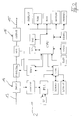
- the electrical signal sequence is a TV commercial.
- the TV spot produced by the production studio 1 passes through a marking device 2 as an electrical signal sequence.
- the marking device 2 works a one-time, i.e. only for this signal sequence for marking usable identification signal in the video signal of the TV picture.
- the identification signal is visualized in a field of view of the marking device 2.
- the marking of the TV spot can take place during the copying work or the creation of the transmission tapes in the production studio 1.
- a total of six broadcasters are named representative of other broadcasters.
- the production studio 1 and / or a customer 4 commissioning the produced TV spot for broadcasting informs a central recording point 5 which identification signal has been incorporated into the TV spot.
- the production studio 1 and / or the customer 4 also communicates the title, length and further data of the TV commercial.
- the information from the production studio 1 and / or the customer 4 is entered and stored by the central recording point 5 in a central data station 6.
- the broadcasting station 3 transmits the marked TV spot by satellite, terrestrial or by cable.
- a receiving station 7 receives the transmitted TV spot by means of a receiving unit 8.
- the receiving station 7 contains a specially developed software and commercially available hardware with possibly further modifications.
- In the receiving station 7 are a commercially available PC and a high-performance modem 9 integrated.
- the receiving station 7 contains several receiving units 8. Each receiving unit 8 is assigned to a receivable transmitter and has a TV / SAT receiver 18 and a receiving electronics 17.
- the receiving electronics 17 recognizes the identification signals received together with the video signals in real time during the entire transmission period of the TV spot.
- a reception station 7 with a plurality of reception units 8 is installed in all regional transmission regions of the broadcasters, with a reception unit 8 being assigned to a transmitter in each case.
- the receiving station 7 also contains a world clock with radio contact.
- the identification signals recognized in the receiving electronics 17 are stored on a data carrier of the receiving station 7 together with a reference to the date of transmission, to the transmitting station 3 and to the transmitting time as control data.
- the stored control data are queried cyclically by the central data station 6.
- the requested control data are transferred to the central data station 6 via modem 9 and an associated data line 10. After data confirmation by data station 6, the requested control data are deleted in receiving station 7.
- the central data station 6 contains software and hardware.
- the software takes over the management of the queried and stored control data, their evaluation, the creation and allocation of identification signals and the communication with the nationwide installed receiving stations 7.
- the hardware of the data station 6 contains a PC network with several work stations and a high-performance modem.
- the data station 6 compares the control data with the information specified by the production studio 1 and / or customer 4 and stored in the data station 6.
- the comparison and evaluation of the control data is carried out customer-specifically according to the following criteria: broadcast date, exact start and end time of broadcast, transmitter, broadcast area, possible disturbances and interruptions, duration of the disturbance with indication of the respective broadcasting area, title of the broadcast TV spot, runtime comparison, indication of runtime changes .
- the evaluated data are stored in a database 11 for statistical evaluations.
- the evaluated data are stored in a customer-oriented manner on disks 12 which the customer 4 receives. For this the customer 4 receives a customer-specific program on which only the disks 12 assigned to him can be read.
- 4 evaluation protocols can also be created for statistical purposes in accordance with the customer's requirement profile.
- the structure and operation of the marking device 2 will be explained in more detail with reference to FIG. 2.
- the marking device 2 is suitable for marking analog video signals in real time. In a further embodiment, such a marking device is also suitable for marking digital video signals in real time.
- the marking device 2 contains software and hardware as well as the necessary inputs and outputs for marking the signal sequence.
- the marking device 2 corresponds to the international studio standard.
- the arrow 13 symbolizes the video signal without marking. It is fed into an input stage 14 of the marking device 2.
- the hardware of the marking device 2 consists of a 19 ⁇ rack housing with an integrated display.
- the marking device 2 is designed as an independent device, i.e. it does not require an external computer for ongoing operation.
- the electronics are divided into an analog part and a digital part.
- the digital part controls the entire sequence of the marking device 2 via a processor.
- the analog part processes the video signals FBAS, Y / C and the component signal Y, R-Y, B-Y in broadcast quality.
- the marking device 2 marks the video signals with the identification signals in real time.
- the marking device 2 contains a central processing unit (CPU), serial interfaces (RS 232, RS 485), memory (ROM, RAM, EEPROM), a screen (DISPLAY), a keyboard (TAST) and a printer connection (PRINTER).
- CPU central processing unit
- serial interfaces RS 232, RS 485
- memory ROM, RAM, EEPROM
- DISPLAY screen
- keyboard TAST
- printer connection PRINTER
- the unmarked video signal (CVBS signal) is amplified in input stage 14 (INPUT).
- the amplified video signal is fed to a line switch (MUX) and a synchronous separation (SYNCSEP).
- the synchronous separation generates signals which contain the vertical and horizontal information of the video signal.
- An oscillator (PLL) generates one for the video signal synchronous clock. This clock is the reference for all subsequent operations.
- a control unit (CTRL) manages a line counter (LCOUNT), a field counter (SCOUNT) and the shift register (SHIFT).
- the control unit (CTRL) is loaded with the line and field information.
- the characteristic data of the identification signal stored in an EEPROM are transferred to the shift register (SHIFT).
- the line switch (MUX) is switched to the shift register (SHIFT) and the data content of the shift register (SHIFT) is encoded in that Video signal incorporated.
- the video signal is then marked with the identification signal and is present at output stage 16.
- the normally unmarked signal sequence passes through a reading unit (CODECTRL). It recognizes whether the signal sequence is really unmarked or is already being fed into input stage 14 by marking it earlier. In this case, the signal sequence is protected from being marked again.
- the older identification signal is not overwritten by a new identification signal. If necessary, the older identification signal can be combined with a new identification signal in such a way that at least partial areas of the older identification signal are retained and the implementation of a renewed marking can thus be seen.
- the identification signal contained in the video signal is decoded again in the receiving electronics 17 after the transmission. Consequently, at least some functional units that correspond to the functional units of the marking device 2 shown in FIG. 2 are integrated in the receiving electronics 17.
Landscapes
- Engineering & Computer Science (AREA)
- Signal Processing (AREA)
- Television Systems (AREA)
Applications Claiming Priority (2)
| Application Number | Priority Date | Filing Date | Title |
|---|---|---|---|
| DE9301779 | 1993-02-10 | ||
| DE9301779U | 1993-02-10 |
Publications (1)
| Publication Number | Publication Date |
|---|---|
| EP0610941A1 true EP0610941A1 (fr) | 1994-08-17 |
Family
ID=6889152
Family Applications (1)
| Application Number | Title | Priority Date | Filing Date |
|---|---|---|---|
| EP94102091A Withdrawn EP0610941A1 (fr) | 1993-02-10 | 1994-02-10 | Dispositif et méthode pour la reconnaissance automatique de séquences de signaux électriques transmis d'un émetteur vers un récepteur |
Country Status (1)
| Country | Link |
|---|---|
| EP (1) | EP0610941A1 (fr) |
Citations (5)
| Publication number | Priority date | Publication date | Assignee | Title |
|---|---|---|---|---|
| US4025851A (en) * | 1975-11-28 | 1977-05-24 | A.C. Nielsen Company | Automatic monitor for programs broadcast |
| US4246440A (en) * | 1977-09-01 | 1981-01-20 | U.S. Philips Corporation | Radio broadcasting system with code signalling |
| US4547804A (en) * | 1983-03-21 | 1985-10-15 | Greenberg Burton L | Method and apparatus for the automatic identification and verification of commercial broadcast programs |
| US4857999A (en) * | 1988-12-20 | 1989-08-15 | Peac Media Research, Inc. | Video monitoring system |
| WO1992019073A1 (fr) * | 1991-04-23 | 1992-10-29 | National Broadcasting Company | Systeme de verification d'emission |
-
1994
- 1994-02-10 EP EP94102091A patent/EP0610941A1/fr not_active Withdrawn
Patent Citations (5)
| Publication number | Priority date | Publication date | Assignee | Title |
|---|---|---|---|---|
| US4025851A (en) * | 1975-11-28 | 1977-05-24 | A.C. Nielsen Company | Automatic monitor for programs broadcast |
| US4246440A (en) * | 1977-09-01 | 1981-01-20 | U.S. Philips Corporation | Radio broadcasting system with code signalling |
| US4547804A (en) * | 1983-03-21 | 1985-10-15 | Greenberg Burton L | Method and apparatus for the automatic identification and verification of commercial broadcast programs |
| US4857999A (en) * | 1988-12-20 | 1989-08-15 | Peac Media Research, Inc. | Video monitoring system |
| WO1992019073A1 (fr) * | 1991-04-23 | 1992-10-29 | National Broadcasting Company | Systeme de verification d'emission |
Similar Documents
| Publication | Publication Date | Title |
|---|---|---|
| DE69435093T2 (de) | Zuschauerermittlungssystem | |
| DE69738024T2 (de) | Fernsehprogrammierungssystem und betriebsverfahren dazu | |
| US4639779A (en) | Method and apparatus for the automatic identification and verification of television broadcast programs | |
| CA1211204A (fr) | Methode et appareil d'identification et de verification automatique de programmes de television | |
| EP0571761A2 (fr) | Appareil vidéo pour traiter des signaux supplémentaires, qui sont transmis pendant les périodes d'effacement de signaux de télévision | |
| DE69936279T2 (de) | Konfigurierbares System für die Ermittlung der Zahl der Zuschauer und der Benutzung von interaktiven Applikationen | |
| DE69826622T2 (de) | Zur Werbungsunterdrückung nicht verwendbares System zur Identifikation von Videofilmausschnitten | |
| DE602004008819T2 (de) | Videoaufnahmegerät und Steuerverfahren dazu | |
| DE60106169T2 (de) | Verfahren und Gerät zur Erfassung der Empfangsqualität von digitalen Rundfunkprogrammen | |
| DE3312723A1 (de) | Signaluebertragungsanlage | |
| DE10031981A1 (de) | Verfahren zur Übertragung von Informationen durch einen Rundfunksender, Verfahren zum Empfang von durch einen Rundfunksender ausgestrahlten Informationen, Verfahren zur Steuerung eines Rundfunkempfängers und Rundfunkempfänger | |
| EP0118104B1 (fr) | Dispositif récepteur de l'éléctronique de loisirs avec mémoire pour les programmes désirés | |
| DE2404074A1 (de) | Verfahren zum erfassen, uebertragen und verarbeiten technischer informationen ueber das fernseheinschaltverhalten von fernsehteilnehmern | |
| DE19757385C2 (de) | Werbeblockerkennungseinrichtung | |
| EP0243740B1 (fr) | Transmission des données de syntonisation d'un récepteur de télévision vers un enregistreur vidéo rattaché | |
| EP0610941A1 (fr) | Dispositif et méthode pour la reconnaissance automatique de séquences de signaux électriques transmis d'un émetteur vers un récepteur | |
| AT391968B (de) | Verfahren und anlage zur ermittlung der fernsehgewohnheiten einer versuchspopulation | |
| EP0604871A1 (fr) | Méthode et dispositif pour l'enregistrement programmable | |
| EP0702489B1 (fr) | Procédé pour commander l'enregistrement d'émission répétées, pour un appareil d'enregistrement électronique grand public | |
| EP0525559B1 (fr) | Méthode et dispositif pour la réception de télétexte avec diminution des temps d'attente lors de l'affichage de pages de télétexte | |
| DE3735780A1 (de) | Verfahren zur programmierung eines empfaengers mit videorecorder zur aufzeichnung von ueber satellit uebertragenen fernsehprogrammbeitraegen | |
| EP0529340B1 (fr) | Méthode et dispositif de mémorisation de programme dans des récepteurs de télévision | |
| DE10238330B3 (de) | Verfahren zum Belegen von Speicherplätzen mit Diensten | |
| EP0902564B1 (fr) | Méthode d'évaluation des signaux numériques, en particulier des signaux de données radio | |
| DE3608847A1 (de) | Videorecorder mit einer einrichtung zur automatischen programmgesteuerten ein- und ausschaltung |
Legal Events
| Date | Code | Title | Description |
|---|---|---|---|
| PUAI | Public reference made under article 153(3) epc to a published international application that has entered the european phase |
Free format text: ORIGINAL CODE: 0009012 |
|
| AK | Designated contracting states |
Kind code of ref document: A1 Designated state(s): AT BE CH DE DK ES FR GB GR IE IT LI LU MC NL PT SE |
|
| RBV | Designated contracting states (corrected) |
Designated state(s): AT CH DE FR GB IT LI NL |
|
| STAA | Information on the status of an ep patent application or granted ep patent |
Free format text: STATUS: THE APPLICATION IS DEEMED TO BE WITHDRAWN |
|
| 18D | Application deemed to be withdrawn |
Effective date: 19950218 |