EP0610941A1 - Device and method for automatic recognition of electrical signal sequences, transmitted from a transmitter station to a receiving station - Google Patents
Device and method for automatic recognition of electrical signal sequences, transmitted from a transmitter station to a receiving station Download PDFInfo
- Publication number
- EP0610941A1 EP0610941A1 EP94102091A EP94102091A EP0610941A1 EP 0610941 A1 EP0610941 A1 EP 0610941A1 EP 94102091 A EP94102091 A EP 94102091A EP 94102091 A EP94102091 A EP 94102091A EP 0610941 A1 EP0610941 A1 EP 0610941A1
- Authority
- EP
- European Patent Office
- Prior art keywords
- signal sequence
- station
- receiving
- signal
- data
- Prior art date
- Legal status (The legal status is an assumption and is not a legal conclusion. Google has not performed a legal analysis and makes no representation as to the accuracy of the status listed.)
- Withdrawn
Links
Images

Classifications
-
- H—ELECTRICITY
- H04—ELECTRIC COMMUNICATION TECHNIQUE
- H04H—BROADCAST COMMUNICATION
- H04H20/00—Arrangements for broadcast or for distribution combined with broadcast
- H04H20/28—Arrangements for simultaneous broadcast of plural pieces of information
-
- H—ELECTRICITY
- H04—ELECTRIC COMMUNICATION TECHNIQUE
- H04H—BROADCAST COMMUNICATION
- H04H20/00—Arrangements for broadcast or for distribution combined with broadcast
- H04H20/12—Arrangements for observation, testing or troubleshooting
- H04H20/14—Arrangements for observation, testing or troubleshooting for monitoring programmes
-
- H—ELECTRICITY
- H04—ELECTRIC COMMUNICATION TECHNIQUE
- H04H—BROADCAST COMMUNICATION
- H04H60/00—Arrangements for broadcast applications with a direct linking to broadcast information or broadcast space-time; Broadcast-related systems
- H04H60/35—Arrangements for identifying or recognising characteristics with a direct linkage to broadcast information or to broadcast space-time, e.g. for identifying broadcast stations or for identifying users
- H04H60/37—Arrangements for identifying or recognising characteristics with a direct linkage to broadcast information or to broadcast space-time, e.g. for identifying broadcast stations or for identifying users for identifying segments of broadcast information, e.g. scenes or extracting programme ID
Definitions
- the invention relates to a method for recognizing an electrical signal sequence with the features of the preamble of claim 1.
- the broadcasters in the television and radio area transmit a variety of different broadcasts, e.g. Commercials, feature films, pieces of music.
- the broadcasts are produced in production studios and then commissioned by the manufacturer for broadcasting from the broadcaster or released for the broadcasting station, the broadcasters also produce broadcasts in their own, internal and external independent production studios, which in turn are also marked there. Since the broadcast of the broadcasts, e.g. Advertisers who are associated with high costs or who also generate large amounts of income are interested in the client or manufacturer of these broadcasts being able to precisely control the transmission of their information. It is particularly important here whether and when the information was actually sent and received in a specific transmission area.
- the invention has for its object to make a method for automatic detection of an electrical signal sequence easier and safer. This object is achieved by the combination of features of claim 1.
- the electrical signal sequence to be transmitted is marked over its entire transmission duration with the aid of an identification signal.
- An electronic "fingerprint" is created on the electrical signal sequence. This marking takes place before or during the transmission.
- To check the transmitted signal sequence only the identification signal transmitted with the currently transmitted signal sequence is recognized and stored. The identification signal is merged with comparison data at a later time for evaluation. As a result, exact transmission and reception protocols can be created solely with the recognized and stored identification signal. Time-consuming data comparisons are avoided.
- the inventive method for recognizing an electrical signal sequence is possible with little electronic computation.
- the detection of electrical signal sequences is conceivable for all transmission systems. It can be video analog or digital image data carriers, as well as analog and digital transmission techniques. Farther the method according to the invention can also be used in the broadcasting sector with both analog and digital signal sequences.
- the identification signal ensures simple, reliable detection of unauthorized copies, since the marking can be used to assign the origin of a signal sequence at any time. This assignment can be further facilitated if the identification signal contains special identification data of the manufacturer, the agency and / or a production studio. This makes it easy to prove the author of a specific electrical signal sequence.
- the identification signal can be incorporated during the first production or when the electrical signal sequence is copied.
- the signal sequence can also be provided with the identification signal during the transmission. In all of these cases, the marking of the electrical signal sequence is possible without any significant additional expenditure of time.
- Fees or license fees can be calculated realistically.
- the protocols enable performance-based billing of signal sequences that have been ordered and to be sent. This also enables realistic billing of the transmission of music pieces that are subject to a fee in the radio area (e.g. GEMA fees).
- the identification signal is not only used for sending and receiving control, but can also be used to assign certain criteria such as Client, editor, program division, author, journalist, production studio or broadcaster.
- the method according to the invention can be used worldwide for all technical formats, transmission systems and standards for the transmission of electrical signal sequences.
- Claim 2 takes into account that the client of TV commercials or a film to be broadcast is interested in a precise broadcast control.
- the addition of the identification signal in the video signal is easily possible with developed hardware and software. Either every field or only every second field of the television picture is marked with the identification signal.
- the image sequence is marked in such a way that the viewer's eye is not irritated or influenced.
- the identification signal remains invisible to the viewer.
- electrical signal sequences can also be marked with identification signals in the radio area according to claim 3.
- the selection of sound frequencies for the identification signals above the human hearing threshold ensures that the identification signals remain inaudible to the listener and thus do not irritate him.
- marking of the signal sequence is e.g. technically possible by appropriate modulation of the carrier frequency of the signal sequence.
- Claim 4 proposes a reception electronics for recognizing the identification signal in the receiving station receiving the signal sequence. It expediently consists of one or more electrical circuits which filter the identification signals from the signal sequence.
- the identification signals are simply stored in the receiving station. A comparison with previously stored reference data is not necessary. The technical effort of the receiving station remains low.
- Claim 6 takes into account a comfortable and at the same time exact statistical evaluation of the transmitted signal sequences at a later point in time.
- the identification duration also stores the transmission time, the broadcaster or the time of transmission of the transmitted electrical signal sequence.
- the identification signals and the mentioned characteristic data of the signal sequence together form the control data.
- Claim 7 proposes electronic processing of the control data received.
- the control data are processed in a central data station, advantageously a computer with commercially available hardware and software.
- the control data stored in the receiving station can thus be queried by the data station.
- the control data is also expediently compared with the reference data specified by the client or customer before the transmission of the signal sequence and stored in the central data station. This means that the large number of control data can be assigned to specific customers.
- the terminal can also create a send and receive log and other statistics in this way. These logs can then be queried by the respective customer. The client can check whether his send orders have been carried out properly.
- Claim 8 proposes a device for marking the electrical signal sequence.
- the marking device contains corresponding electronic functional units, with the aid of which the identification signal already programmed in the marking device is incorporated into the as yet unmarked electrical signal sequence. With the aid of this marking device, the marking of the signal sequence can be carried out in a particularly user-friendly manner.
- a very effective protection against unwanted overwriting of an already marked signal sequence with a new identification signal is provided in the marking device.
- the marking device recognizes a signal sequence that has already been marked and refuses to mark the signal sequence again. If necessary, partial areas of the identification signal can also be released for overwriting.
- the older identification signal can then be combined with a new identification signal in such a way that at least partial areas of the older identification signal are retained and the implementation of a new marking can thus be seen.
- the receiving station is constructed in several parts and thereby ensures the storage and further processing of the control data.
- a plurality of data networks e.g. ISDN or telephone network available.
- a receiving station contains a plurality of receiving units, each with receiving electronics. Each receiver unit is assigned to a transmitter. In this way, a single receiving station can monitor many transmitters at the same time.
- Claim 12 ensures that the client or customer can carry out a complete control of all the electrical signal sequences that are ordered and to be sent by him.
- Claim 13 takes into account the central processing of all customer-specific control data.
- the customer can thereby process the processed control data received in a simple manner from a single central data station and at the same time guarantees complete control and evaluation of all desired transmission and reception areas.
- Several receiving stations can be connected directly to the central data station or indirectly to the central data station via a collecting point, a so-called concentrator.
- the concentrator collects the control data from several receiving stations and then transfers them to the central data station.
- Such concentrators are used above all at long distances between the receiving station and the central data station and enable more cost-effective data transfer.
- the sender data station is connected to its own internal receiving station (directly) after its transmission output.
- the broadcaster can either partially or completely carry out the possibilities described at the outset for monitoring and evaluating electrical signal sequences.
- the material produced by the broadcasting station itself and also live broadcasts also receive a specific broadcast identifier with the marking. This takes place on the one hand when the signal sequence passes through the marking device in their own internal production studios, in the case of live broadcasts each time when they pass through the marking device, and on the other hand in their free production studios e.g. by means of a chip card on which the transmitter identifier is contained and which are additionally read into the markings to be issued.
- the electrical signal sequence is a TV commercial.
- the TV spot produced by the production studio 1 passes through a marking device 2 as an electrical signal sequence.
- the marking device 2 works a one-time, i.e. only for this signal sequence for marking usable identification signal in the video signal of the TV picture.
- the identification signal is visualized in a field of view of the marking device 2.
- the marking of the TV spot can take place during the copying work or the creation of the transmission tapes in the production studio 1.
- a total of six broadcasters are named representative of other broadcasters.
- the production studio 1 and / or a customer 4 commissioning the produced TV spot for broadcasting informs a central recording point 5 which identification signal has been incorporated into the TV spot.
- the production studio 1 and / or the customer 4 also communicates the title, length and further data of the TV commercial.
- the information from the production studio 1 and / or the customer 4 is entered and stored by the central recording point 5 in a central data station 6.
- the broadcasting station 3 transmits the marked TV spot by satellite, terrestrial or by cable.
- a receiving station 7 receives the transmitted TV spot by means of a receiving unit 8.
- the receiving station 7 contains a specially developed software and commercially available hardware with possibly further modifications.
- In the receiving station 7 are a commercially available PC and a high-performance modem 9 integrated.
- the receiving station 7 contains several receiving units 8. Each receiving unit 8 is assigned to a receivable transmitter and has a TV / SAT receiver 18 and a receiving electronics 17.
- the receiving electronics 17 recognizes the identification signals received together with the video signals in real time during the entire transmission period of the TV spot.
- a reception station 7 with a plurality of reception units 8 is installed in all regional transmission regions of the broadcasters, with a reception unit 8 being assigned to a transmitter in each case.
- the receiving station 7 also contains a world clock with radio contact.
- the identification signals recognized in the receiving electronics 17 are stored on a data carrier of the receiving station 7 together with a reference to the date of transmission, to the transmitting station 3 and to the transmitting time as control data.
- the stored control data are queried cyclically by the central data station 6.
- the requested control data are transferred to the central data station 6 via modem 9 and an associated data line 10. After data confirmation by data station 6, the requested control data are deleted in receiving station 7.
- the central data station 6 contains software and hardware.
- the software takes over the management of the queried and stored control data, their evaluation, the creation and allocation of identification signals and the communication with the nationwide installed receiving stations 7.
- the hardware of the data station 6 contains a PC network with several work stations and a high-performance modem.
- the data station 6 compares the control data with the information specified by the production studio 1 and / or customer 4 and stored in the data station 6.
- the comparison and evaluation of the control data is carried out customer-specifically according to the following criteria: broadcast date, exact start and end time of broadcast, transmitter, broadcast area, possible disturbances and interruptions, duration of the disturbance with indication of the respective broadcasting area, title of the broadcast TV spot, runtime comparison, indication of runtime changes .
- the evaluated data are stored in a database 11 for statistical evaluations.
- the evaluated data are stored in a customer-oriented manner on disks 12 which the customer 4 receives. For this the customer 4 receives a customer-specific program on which only the disks 12 assigned to him can be read.
- 4 evaluation protocols can also be created for statistical purposes in accordance with the customer's requirement profile.
- the structure and operation of the marking device 2 will be explained in more detail with reference to FIG. 2.
- the marking device 2 is suitable for marking analog video signals in real time. In a further embodiment, such a marking device is also suitable for marking digital video signals in real time.
- the marking device 2 contains software and hardware as well as the necessary inputs and outputs for marking the signal sequence.
- the marking device 2 corresponds to the international studio standard.
- the arrow 13 symbolizes the video signal without marking. It is fed into an input stage 14 of the marking device 2.
- the hardware of the marking device 2 consists of a 19 ⁇ rack housing with an integrated display.
- the marking device 2 is designed as an independent device, i.e. it does not require an external computer for ongoing operation.
- the electronics are divided into an analog part and a digital part.
- the digital part controls the entire sequence of the marking device 2 via a processor.
- the analog part processes the video signals FBAS, Y / C and the component signal Y, R-Y, B-Y in broadcast quality.
- the marking device 2 marks the video signals with the identification signals in real time.
- the marking device 2 contains a central processing unit (CPU), serial interfaces (RS 232, RS 485), memory (ROM, RAM, EEPROM), a screen (DISPLAY), a keyboard (TAST) and a printer connection (PRINTER).
- CPU central processing unit
- serial interfaces RS 232, RS 485
- memory ROM, RAM, EEPROM
- DISPLAY screen
- keyboard TAST
- printer connection PRINTER
- the unmarked video signal (CVBS signal) is amplified in input stage 14 (INPUT).
- the amplified video signal is fed to a line switch (MUX) and a synchronous separation (SYNCSEP).
- the synchronous separation generates signals which contain the vertical and horizontal information of the video signal.
- An oscillator (PLL) generates one for the video signal synchronous clock. This clock is the reference for all subsequent operations.
- a control unit (CTRL) manages a line counter (LCOUNT), a field counter (SCOUNT) and the shift register (SHIFT).
- the control unit (CTRL) is loaded with the line and field information.
- the characteristic data of the identification signal stored in an EEPROM are transferred to the shift register (SHIFT).
- the line switch (MUX) is switched to the shift register (SHIFT) and the data content of the shift register (SHIFT) is encoded in that Video signal incorporated.
- the video signal is then marked with the identification signal and is present at output stage 16.
- the normally unmarked signal sequence passes through a reading unit (CODECTRL). It recognizes whether the signal sequence is really unmarked or is already being fed into input stage 14 by marking it earlier. In this case, the signal sequence is protected from being marked again.
- the older identification signal is not overwritten by a new identification signal. If necessary, the older identification signal can be combined with a new identification signal in such a way that at least partial areas of the older identification signal are retained and the implementation of a renewed marking can thus be seen.
- the identification signal contained in the video signal is decoded again in the receiving electronics 17 after the transmission. Consequently, at least some functional units that correspond to the functional units of the marking device 2 shown in FIG. 2 are integrated in the receiving electronics 17.
Abstract
Description
Die Erfindung betrifft ein Verfahren zur Erkennung einer elektrischen Signalfolge mit den Merkmalen des Oberbegriffs des Anspruches 1.The invention relates to a method for recognizing an electrical signal sequence with the features of the preamble of claim 1.
Die Sendeanstalten im Fernseh- und Rundfunkbereich übertragen eine Vielzahl unterschiedlichster Sendebeiträge, z.B. Werbespots, Spielfilme, Musikstücke. Die Sendebeiträge werden in Produktionsstudios hergestellt und dann vom Hersteller bei der Sendeanstalt zur Ausstrahlung in Auftrag gegeben oder für die Sendeanstalt gebührenpflichtig freigegeben, ebenso produzieren die Sendeanstalten in ihren eigenen, internen und externen freien Produktionsstudios Sendebeiträge, die wiederum auch dort markiert werden. Da die Ausstrahlung der Sendebeiträge, wie z.B. Werbespots, mit hohen Kosten verbunden sind bzw. auch große Einnahmen ermöglichen, sind die Auftraggeber bzw. Hersteller dieser Sendebeiträge daran interessiert, die Übertragung ihrer Informationen genau kontrollieren zu können. Hierbei ist vor allem wichtig, ob und wann die Informationen tatsächlich gesendet und in einem bestimmten Sendegebiet empfangen wurden.The broadcasters in the television and radio area transmit a variety of different broadcasts, e.g. Commercials, feature films, pieces of music. The broadcasts are produced in production studios and then commissioned by the manufacturer for broadcasting from the broadcaster or released for the broadcasting station, the broadcasters also produce broadcasts in their own, internal and external independent production studios, which in turn are also marked there. Since the broadcast of the broadcasts, e.g. Advertisers who are associated with high costs or who also generate large amounts of income are interested in the client or manufacturer of these broadcasts being able to precisely control the transmission of their information. It is particularly important here whether and when the information was actually sent and received in a specific transmission area.
Aus DE 42 08 932 C1 ist ein elektronisches Verfahren für die Sendekontrolle einer elektrischen Signalfolge bekannt. Dieses Verfahren ermöglicht die automatische Wiedererkennung von elektrischen Signalfolgen. Hierzu werden die elektrischen Signalfolgen bereits zu einem Zeitpunkt vor der Übertragung aufgenommen und nach einer Datenreduktion abgespeichert. Die abgespeicherten Daten werden zu einem späteren Zeitpunkt, nämlich bei der tatsächlichen Übertragung der elektrischen Signalfolge, in einer Vergleichereinheit miteinander verglichen. Bei einer überwiegenden Übereinstimmung der gespeicherten Werte mit den im Echtzeitbetrieb ankommenden Werten wird ein Wiedererkennungssignal ausgegeben. Mit Hilfe dieser Wiedererkennungssignale lassen sich Sendeprotokolle zu statistischen Auswertezwecken erstellen. Das bekannte Verfahren hat jedoch den Nachteil, daß es bereits vor der Übertragung der elektrischen Signalfolge einen erheblichen Arbeitsaufwand zur späteren Kontrolle erfordert. Jede elektrische Signalfolge muß in ihrer gesamten Sendedauer bereits vor der eigentlichen Übertragung in einer reduzierten Form abgespeichert werden. Dies ist sehr zeitaufwendig und somit kostenintensiv. Außerdem erfordert dieser Arbeitsschritt einen großen Aufwand an Rechenelektronik und Speicherkapazität. Der Vergleich der tatsächlich gesendeten elektrischen Signalfolge mit den abgespeicherten Daten wird im Echtzeitbetrieb durchgeführt. Der Echtzeitbetrieb erfordert jedoch eine stark reduzierte Datenform der miteinander zu vergleichenden Signalfolgen. Aus der Datenreduktion ergibt sich eine bestimmte Fehlerwahrscheinlichkeit beim Vergleich. Dementsprechend werden die Signalfolgen auch nur auf eine überwiegende Übereinstimmung überprüft. Die erstellten Sendeprotokolle können deshalb fehlerhaft sein. Außerdem ist das bekannte Verfahren weder für Live-Sendungen noch für den Hörfunk geeignet.From DE 42 08 932 C1 an electronic method for the transmission control of an electrical signal sequence is known. This procedure enables automatic recognition of electrical signal sequences. For this purpose, the electrical signal sequences are recorded at a point in time before the transmission and are stored after a data reduction. The stored data are compared at a later point in time, namely when the electrical signal sequence is actually transmitted, in a comparator unit. If the stored values largely agree with the values arriving in real-time operation, a recognition signal is output. With the help of these recognition signals create transmission protocols for statistical evaluation purposes. However, the known method has the disadvantage that it requires a considerable amount of work for later checking even before the electrical signal sequence is transmitted. Each electrical signal sequence must be stored in a reduced form in its entire transmission time before the actual transmission. This is very time consuming and therefore costly. In addition, this step requires a great deal of computing electronics and storage capacity. The comparison of the actually transmitted electrical signal sequence with the stored data is carried out in real time. However, real-time operation requires a greatly reduced data form of the signal sequences to be compared with one another. The data reduction results in a certain probability of error in the comparison. Accordingly, the signal sequences are only checked for a predominant match. The transmission protocols created can therefore be incorrect. In addition, the known method is neither suitable for live broadcasts nor for radio.
Ausgehend von den geschilderten Nachteilen liegt der Erfindung die Aufgabe zugrunde, ein Verfahren zur automatischen Erkennung einer elektrischen Signalfolge einfacher und sicherer zu gestalten. Diese Aufgabe wird durch die Merkmalskombination des Anspruches 1 gelöst.Based on the disadvantages described, the invention has for its object to make a method for automatic detection of an electrical signal sequence easier and safer. This object is achieved by the combination of features of claim 1.
Erfindungsgemäß wird die zu sendende elektrische Signalfolge über ihre gesamte Sendedauer hinweg mit Hilfe eines Kennsignales markiert. Es entsteht ein elektronischer "Fingerabdruck" auf der elektrischen Signalfolge. Diese Markierung erfolgt vor oder während der Übertragung. Zur Kontrolle der gesendeten Signalfolge wird lediglich das mit der gerade gesendeten Signalfolge übertragene Kennsignal erkannt und abgespeichert. Das Kennsignal wird zu einem späteren Zeitpunkt zur Auswertung mit Vergleichsdaten zusammengeführt. Dadurch lassen sich allein mit dem erkannten und abgespeicherten Kennsignal exakte Sende- und Empfangsprotokolle erstellen. Aufwendige Datenvergleiche werden vermieden. Das erfindungsmäßige Verfahren zur Erkennung einer elektrischen Signalfolge ist mit geringem elektronischen Rechenaufwand möglich.According to the invention, the electrical signal sequence to be transmitted is marked over its entire transmission duration with the aid of an identification signal. An electronic "fingerprint" is created on the electrical signal sequence. This marking takes place before or during the transmission. To check the transmitted signal sequence, only the identification signal transmitted with the currently transmitted signal sequence is recognized and stored. The identification signal is merged with comparison data at a later time for evaluation. As a result, exact transmission and reception protocols can be created solely with the recognized and stored identification signal. Time-consuming data comparisons are avoided. The inventive method for recognizing an electrical signal sequence is possible with little electronic computation.
Die Erkennung elektrischer Signalfolgen ist für alle Übertragungssysteme denkbar. Es kann sich um videotechnisch analoge oder digitale Bilddatenträger handeln, sowie auch um analoge und digitale Übertragungstechniken. Weiterhin ist das erfindungsmäßige Verfahren auch im Rundfunk-Bereich sowohl bei analogen als auch bei digitalen Signalfolgen einsetzbar.The detection of electrical signal sequences is conceivable for all transmission systems. It can be video analog or digital image data carriers, as well as analog and digital transmission techniques. Farther the method according to the invention can also be used in the broadcasting sector with both analog and digital signal sequences.
Weiterhin gewährleistet das Kennsignal auf einfache Weise einen sicheren Nachweis von unerlaubten Kopien, da mit der Markierung der Ursprung einer Signalfolge jederzeit genau zugeordnet werden kann. Diese Zuordnung kann zusätzlich erleichtert werden, indem das Kennsignal spezielle Kennungsdaten des Herstellers, der Agentur und/oder eines Produktionsstudios enthält. Der Nachweis des Urhebers einer bestimmten elektrischen Signalfolge ist dadurch auf einfache Weise möglich.Furthermore, the identification signal ensures simple, reliable detection of unauthorized copies, since the marking can be used to assign the origin of a signal sequence at any time. This assignment can be further facilitated if the identification signal contains special identification data of the manufacturer, the agency and / or a production studio. This makes it easy to prove the author of a specific electrical signal sequence.
Das Kennsignal kann bereits bei der erstmaligen Produktion oder auch beim Kopieren der elektrischen Signalfolge eingearbeitet werden. Auch kann die Signalfolge bei Live-Sendungen oder Live-Einspielungen während der Übertragung mit dem Kennsignal versehen werden. In allen diesen Fällen ist die Markierung der elektrischen Signalfolge ohne nennenswerten zusätzlichen Zeitaufwand möglich.The identification signal can be incorporated during the first production or when the electrical signal sequence is copied. In the case of live broadcasts or live recordings, the signal sequence can also be provided with the identification signal during the transmission. In all of these cases, the marking of the electrical signal sequence is possible without any significant additional expenditure of time.
Honorare oder Lizenzgebühren können realistisch abgerechnet werden. Auβerdem ermöglichen die Protokolle eine leistungsbezogene Abrechnung von in Auftrag gegebenen, zu sendenden Signalfolgen. Auch eine realistische Abrechnung der Übertragung von gebührenpflichtigen Musikstücken im Rundfunkbereich (z.B. GEMA-Gebühren) ist dadurch möglich.Fees or license fees can be calculated realistically. In addition, the protocols enable performance-based billing of signal sequences that have been ordered and to be sent. This also enables realistic billing of the transmission of music pieces that are subject to a fee in the radio area (e.g. GEMA fees).
Das Kennsignal dient nicht allein zur Sende- und Empfangskontrolle, sondern kann auch der Zuordnung bestimmter Kriterien wie z.B. Auftraggeber, Redaktion, Programmsparte, Autor, Journalist, Produktionsstudio oder Sendeanstalt dienen.The identification signal is not only used for sending and receiving control, but can also be used to assign certain criteria such as Client, editor, program division, author, journalist, production studio or broadcaster.
Das erfindungsmäßige Verfahren ist weltweit für alle technischen Formate, Übertragungssysteme und Normen zur Übertragung elektrischer Signalfolgen einsetzbar.The method according to the invention can be used worldwide for all technical formats, transmission systems and standards for the transmission of electrical signal sequences.
Anspruch 2 berücksichtigt, daß die Auftraggeber von zu sendenden TV-Werbespots oder eines Filmes an einer genauen Sendekontrolle interessiert sind. Die Hinzufügung des Kennsignals in das Videosignal ist mit einer entwickelten Hard- und Software problemlos möglich. Es wird entweder jedes Halbbild oder auch nur jedes zweite Halbbild des Femsehbildes mit dem Kennsignal markiert.
Technisch erfolgt die Markierung der Bildsequenz derart, daß das Auge des Zuschauers nicht irritiert oder beeinflußt wird. Das Kennsignal bleibt für den Zuschauer unsichtbar.Technically, the image sequence is marked in such a way that the viewer's eye is not irritated or influenced. The identification signal remains invisible to the viewer.
Analog zu Anspruch 2 sind gemäß Anspruch 3 elektrische Signalfolgen auch im Hörfunkbereich mit Kennsignalen markierbar. Die Auswahl von Tonfrequenzen für die Kennsignale oberhalb der menschlichen Hörschwelle gewährleistet, daß die Kennsignale für den Zuhörer unhörbar bleiben und ihn somit nicht irritieren. Eine derartige Markierung der Signalfolge ist z.B. durch eine entsprechende Modulation der Trägerfrequenz der Signalfolge technisch möglich.Analogous to claim 2, electrical signal sequences can also be marked with identification signals in the radio area according to
Anspruch 4 schlägt zur Erkennung des Kennsignals in der die Signalfolge empfangenden Empfangsstation eine Empfangselektronik vor. Sie besteht zweckmäßig aus einer oder mehreren elektrischen Schaltungen, die aus der Signalfolge die Kennsignale herausfiltern.Claim 4 proposes a reception electronics for recognizing the identification signal in the receiving station receiving the signal sequence. It expediently consists of one or more electrical circuits which filter the identification signals from the signal sequence.
Gemäß Anspruch 5 werden die Kennsignale in der Empfangsstation einfach abgespeichert. Ein Vergleich mit vorher abgespeicherten Referenzdaten ist nicht erforderlich. Der technische Aufwand der Empfangsstation bleibt dadurch gering.According to
Anspruch 6 berücksichtigt eine bequeme und gleichzeitig exakte statistische Auswertung der gesendeten Signalfolgen zu einem späteren Zeitpunkt. So wird beispielsweise mit den Kennsignalen auch die Sendedauer, die Sendeanstalt oder der Sendezeitpunkt der gesendeten elektrischen Signalfolge abgespeichert. Die Kennsignale und die genannten charakteristischen Daten der Signalfolge bilden zusammen die Kontrolldaten.Claim 6 takes into account a comfortable and at the same time exact statistical evaluation of the transmitted signal sequences at a later point in time. For example, the identification duration also stores the transmission time, the broadcaster or the time of transmission of the transmitted electrical signal sequence. The identification signals and the mentioned characteristic data of the signal sequence together form the control data.
Anspruch 7 schlägt eine elektronische Verarbeitung der erhaltenen Kontrolldaten vor. Die Verarbeitung der Kontrolldaten erfolgt in einer zentralen Datenstation, zweckmäßig einem Computer mit handelsüblicher Hardware und Software. So können die in der Empfangsstation abgespeicherten Kontrolldaten von der Datenstation abgefragt werden. In der Datenstation erfolgt zweckmäßig auch ein Vergleich der Kontrolldaten mit den vom Auftraggeber bzw. Kunden vor der Übertragung der Signalfolge angegebenen und in der zentralen Datenstation gespeicherten Referenzdaten. Dadurch kann die Vielzahl der Kontrolldaten kundenspezifisch zugeordnet werden. Für jeden Auftraggeber bzw. Kunden kann die Datenstation auf diese Weise auch ein Sende- und Empfangsprotokoll sowie weitere Statistiken erstellen. Diese Protokolle können dann vom jeweiligen Kunden abgefragt werden. Der Auftraggeber kann überprüfen, ob seine Sendeaufträge ordnungsgemäß durchgeführt wurden.Claim 7 proposes electronic processing of the control data received. The control data are processed in a central data station, advantageously a computer with commercially available hardware and software. The control data stored in the receiving station can thus be queried by the data station. In the data station, the control data is also expediently compared with the reference data specified by the client or customer before the transmission of the signal sequence and stored in the central data station. This means that the large number of control data can be assigned to specific customers. For every client or customer the terminal can also create a send and receive log and other statistics in this way. These logs can then be queried by the respective customer. The client can check whether his send orders have been carried out properly.
Anspruch 8 schlägt eine Vorrichtung zur Markierung der elektrischen Signalfolge vor. Das Markierungsgerät enthält entsprechende elektronische Funktionseinheiten, mit deren Hilfe das bereits im Markierungsgerät einprogrammierte Kennsignal in die noch unmarkierte elektrische Signalfolge eingearbeitet wird. Mit Hilfe dieses Markierungsgerätes ist die Markierung der Signalfolge besonders bedienungsfreundlich durchführbar.
Gemäß Anspruch 9 ist im Markierungsgerät ein sehr wirksamer Schutz gegen ein ungewolltes Überschreiben einer bereits markierten Signalfolge mit einem neuen Kennsignal vorgesehen. Das Markierungsgerät erkennt eine bereits markierte Signalfolge und verweigert eine erneute Markierung der Signalfolge. Gegebenenfalls können auch Teilbereiche des Kennsignales für das Überschreiben freigegeben werden. Das ältere Kennsignal ist dann mit einem neuen Kennsignal derart kombinierbar, daß zumindest Teilbereiche des älteren Kennsignales erhalten bleiben und dadurch die Durchführung einer erneuten Markierung ersichtlich ist.According to
Gemäß Anspruch 10 ist die Empfangsstation mehrteilig aufgebaut und gewährleistet dadurch die Abspeicherung und Weiterverarbeitung der Kontrolldaten. Für die Realisierung der Datenleitung ist eine Mehrzahl von Datennetzen, z.B. ISDN oder Telefonnetz verfügbar.According to
Gemäß Anspruch 11 enthält eine Empfangsstation mehrere Empfangseinheiten mit jeweils einer Empfangselektronik. Jede Empfangseinheit ist einem Sender zugeordnet. Auf diese Weise kann eine einzige Empfangsstation gleichzeitig viele Sender überwachen.According to
Anspruch 12 gewährleistet, daß der Auftraggeber bzw. Kunde eine vollständige Kontrolle sämtlicher von ihm in Auftrag gegebenen und zu sendenden elektrischen Signalfolgen durchführen kann.
Anspruch 13 berücksichtigt eine zentrale Verarbeitung sämtlicher kundenspezifischer Kontrolldaten. Der Kunde kann dadurch die verarbeiteten Kontrolldaten in einfacher Weise von einer einzigen zentralen Datenstation erhalten und hat dabei gleichzeitig die Gewähr der vollständigen Kontrolle und Auswertung sämtlicher gewünschten Sende- und Empfangsgebiete. Mehrere Empfangsstationen können direkt an die zentrale Datenstation oder auch indirekt über eine Sammelstelle, einem sogenannten Konzentrator, an die zentrale Datenstation angeschlossen sein. Der Konzentrator sammelt die Kontrolldaten mehrerer Empfangsstationen und transferiert sie dann an die zentrale Datenstation weiter. Derartige Konzentratoren werden vor allem bei großen Entfernungen zwischen Empfangsstation und zentraler Datenstation eingesetzt und ermöglichen einen kostengünstigeren Datentransfer.
Es ist auch denkbar, die Sendeanstalt mit einer eigenen Datenstation auszurüsten. Die Sendeanstalt kann dann ihren Sendeablauf selbst auswerten, archivieren und Übersichten vom Sendeablauf erstellen. Dadurch sind exakte Aussagen über Sendeablauf und -struktur eines bestimmten Sendezeitraumes möglich.It is also conceivable to equip the broadcaster with its own data station. The broadcaster can then evaluate and archive its broadcasting process itself and create overviews of the broadcasting process. This makes it possible to make precise statements about the transmission process and structure of a specific transmission period.
Die Sender-Datenstation ist wie die zentrale Datenstation an eine eigene, interne Empfangsstation (direkt) nach ihrem Sendeausgang angeschlossen. Mit Hilfe der Sender-Datenstation kann die Sendeanstalt die eingangs beschriebenen Möglichkeiten zur Überwachung und Auswertung elektrischer Signalfolgen entweder teilweise oder vollständig selber durchführen.Like the central data station, the sender data station is connected to its own internal receiving station (directly) after its transmission output. With the aid of the transmitter data station, the broadcaster can either partially or completely carry out the possibilities described at the outset for monitoring and evaluating electrical signal sequences.
Weiterhin erhält das von der Sendestation selbst produzierte Material und auch Live-Sendungen zusätzlich eine spezifische Senderkennung mit der Markierung. Dies erfolgt zum einen beim Durchgang der Signalfolge durch das Markierungsgerät in deren eigenen, internen Produktionsstudios, bei Live-Sendungen jeweils bei Durchgang durch das Markierungsgerät, und zum anderen in deren freien Produktionsstudios z.B. mittels einer Chipkarte, auf der die Senderkennung enthalten ist und die in die zu vergebenden Markierungen zusätzlich eingelesen werden.Furthermore, the material produced by the broadcasting station itself and also live broadcasts also receive a specific broadcast identifier with the marking. This takes place on the one hand when the signal sequence passes through the marking device in their own internal production studios, in the case of live broadcasts each time when they pass through the marking device, and on the other hand in their free production studios e.g. by means of a chip card on which the transmitter identifier is contained and which are additionally read into the markings to be issued.
Dadurch können in den einzelnen Sendebereichen einer Sendeanstalt auftretende Übertragungsfehler genau erfaßt werden. Folglich kann jedes Sendesystem kostengünstig, verwaltungstechnisch einfach und mit großer Zuverlässigkeit überwacht werden.As a result, transmission errors occurring in the individual transmission areas of a broadcaster can be detected precisely. As a result, each transmission system can be monitored inexpensively, in terms of administration, and with great reliability.
Die Erfindung wird anhand der in den Figuren dargestellten Ausführungsbeispiele näher erläutert. Es zeigen:
- Fig. 1
- ein schematischer Ablaufplan des erfindungsmäßigen Verfahrens
- Fig. 2
- ein Blockschaltbild des Markierungsgerätes zur Markierung einer elektrischen Signalfolge.
- Fig. 1
- a schematic flow chart of the inventive method
- Fig. 2
- a block diagram of the marking device for marking an electrical signal sequence.
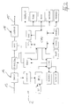
Anhand von Fig. 1 wird der Verfahrensablauf zur Markierung einer elektrischen Signalfolge und zur automatischen Erkennung der markierten und übertragenen Signalfolge erläutert. Im Ausführungsbeispiel von Fig. 1 ist die elektrische Signalfolge ein TV-Werbespot.The method sequence for marking an electrical signal sequence and for automatically recognizing the marked and transmitted signal sequence is explained with reference to FIG. 1. In the exemplary embodiment in FIG. 1, the electrical signal sequence is a TV commercial.
Der vom Produktionsstudio 1 produzierte TV-Spot durchläuft als elektrische Signalfolge ein Markierungsgerät 2. Zur Markierung der Signalfolge arbeitet das Markierungsgerät 2 ein einmaliges, d.h. nur für diese Signalfolge zur Markierung verwendbares Kennsignal in das Video-Signal des TV-Bildes ein. Das Kennsignal wird in einem Sichtfeld des Markierungsgerätes 2 visualisiert.The TV spot produced by the production studio 1 passes through a marking
Die Markierung des TV-Spots kann während der Kopierarbeiten oder dem Erstellen der Sendebänder im Produktionsstudio 1 erfolgen.The marking of the TV spot can take place during the copying work or the creation of the transmission tapes in the production studio 1.
In Fig. 1 sind stellvertretend für weitere Sendeanstalten insgesamt sechs Sendeanstalten genannt.In Fig. 1, a total of six broadcasters are named representative of other broadcasters.
Das Produktionsstudio 1 und/oder ein den produzierten TV-Spot zur Ausstrahlung in Auftrag gebender Kunde 4 teilt einer zentralen Erfassungsstelle 5 mit, welches Kennsignal in den TV-Spot eingearbeitet wurde. Dabei teilt das Produktionsstudio 1 und/oder der Kunde 4 auch Titel, Länge und weitere Daten des TV-Spots mit. Die Informationen des Produktionsstudios 1 und/oder des Kunden 4 werden von der zentralen Erfassungsstelle 5 in eine zentrale Datenstation 6 eingegeben und abgespeichert.The production studio 1 and / or a customer 4 commissioning the produced TV spot for broadcasting informs a
Die Sendestation 3 überträgt den markierten TV-Spot per Satellit, terrestrisch oder per Kabel. Eine Empfangsstation 7 empfängt den übertragenen TV-Spot mittels einer Empfangseinheit 8. Die Empfangsstation 7 enthält eine eigens entwickelte Software und handelsübliche Hardware mit gegebenenfalls weiteren Modifikationen. In der Empfangsstation 7 sind ein handelsüblicher PC und ein Hochleistungsmodem 9 integriert. Die Empfangsstation 7 enthält mehrere Empfangseinheiten 8. Jede Empfangseinheit 8 ist einem empfangbaren Sender zugeordnet und weist einen TV/SAT-Receiver 18 und eine Empfangselektronik 17 auf. Die Empfangselektronik 17 erkennt während der gesamten Sendedauer des TV-Spots die zusammen mit den Videosignalen empfangenen Kennsignale in Echtzeit.The
In allen regionalen Sendegebieten der Sendeanstalten wird eine Empfangsstation 7 mit mehreren Empfangseinheiten 8 installiert, wobei jeweils eine Empfangseinheit 8 einem Sender zugeordnet ist.A reception station 7 with a plurality of
Die Empfangsstation 7 enthält außerdem eine Weltzeituhr mit Funkkontakt. Die in der Empfangselektronik 17 erkannten Kennsignale werden zusammen mit einem Hinweis auf das Sendedatum, auf die Sendestation 3 und auf die Sendezeit als Kontrolldaten auf einen Datenträger der Empfangsstation 7 abgespeichert. Die abgespeicherten Kontrolldaten werden zyklisch von der zentralen Datenstation 6 abgefragt. Per Modem 9 und einer zugehörigen Datenleitung 10 werden die abgefragten Kontrolldaten an die zentrale Datenstation 6 transferiert. Nach Datenbestätigung durch die Datenstation 6 werden die abgefragten Kontrolldaten in der Empfangsstation 7 gelöscht.The receiving station 7 also contains a world clock with radio contact. The identification signals recognized in the receiving
Die zentrale Datenstation 6 beinhaltet Software und Hardware. Die Software übernimmt die Verwaltung der abgefragten und gespeicherten Kontrolldaten, deren Auswertung, die Erstellung und Vergabe von Kennsignalen und die Kommunikation mit den flächendeckend installierten Empfangsstationen 7. Die Hardware der Datenstation 6 enthält ein PC-Netzwerk mit mehreren Arbeitsstationen und einem Hochleistungsmodem. Die Datenstation 6 vergleicht die Kontrolldaten mit den vom Produktionsstudio 1 und/oder Kunden 4 angegebenen und in der Datenstation 6 gespeicherten Informationen. Der Vergleich und die Auswertung der Kontrolldaten erfolgt kundenspezifisch nach folgenden Kriterien: Sendedatum, exakte Sendeanfangsuhrzeit und -enduhrzeit, Sender, Sendegebiet, mögliche Störungen und Unterbrechungen, Störungsdauer mit gegebenenfalls Angabe des jeweiligen Ausstrahlungsgebietes, Titel des gesendeten TV-Spots, Laufzeitvergleich, Hinweis auf Laufzeitänderungen.The central data station 6 contains software and hardware. The software takes over the management of the queried and stored control data, their evaluation, the creation and allocation of identification signals and the communication with the nationwide installed receiving stations 7. The hardware of the data station 6 contains a PC network with several work stations and a high-performance modem. The data station 6 compares the control data with the information specified by the production studio 1 and / or customer 4 and stored in the data station 6. The comparison and evaluation of the control data is carried out customer-specifically according to the following criteria: broadcast date, exact start and end time of broadcast, transmitter, broadcast area, possible disturbances and interruptions, duration of the disturbance with indication of the respective broadcasting area, title of the broadcast TV spot, runtime comparison, indication of runtime changes .
Die ausgewerteten Daten werden in einer Datenbank 11 für statistische Auswertungen abgespeichert. Außerdem werden die ausgewerteten Daten kundenorientiert auf Disketten 12 abgespeichert, die der Kunde 4 erhält. Hierzu erhält der Kunde 4 ein kundenspezifisches Programm, auf dem ausschließlich ihm zugeordnete Disketten 12 gelesen werden können. In der Datenstation 6 können außerdem entsprechend dem Anforderungsprofil des Kunden 4 Auswerteprotokolle für statistische Zwecke erstellt werden.The evaluated data are stored in a
Anhand von Fig. 2 wird der Aufbau und die Arbeitsweise des Markierungsgerätes 2 näher erläutert.The structure and operation of the marking
Das Markierungsgerät 2 ist zur Markierung analoger Videosignale in Echtzeit geeignet. In einer weiteren Ausführungsform ist ein derartiges Markierungsgerät auch für die Markierung digitaler Videosignale in Echtzeit geeignet.The marking
Das Markierungsgerät 2 enthält Software und Hardware sowie die notwendigen Eingänge und Ausgänge zur Markierung der Signalfolge. Das Markierungsgerät 2 entspricht der internationalen Studionorm. Der Pfeil 13 symbolisiert das Videosignal ohne Markierung. Es wird in eine Eingangsstufe 14 des Markierungsgerätes 2 eingespeist. Der Pfeil 15 hingegen symbolisiert das mit dem Kennsignal markierte Videosignal, welches an einer Ausgangsstufe 16 des Markierungsgerätes 2 zur Verfügung steht.The marking
Die Hardware des Markierungsgerätes 2 besteht aus einem 19˝-Rackgehäuse mit integriertem Display. Das Markierungsgerät 2 ist als eigenständiges Gerät konzipiert, d.h. es benötigt für den laufenden Betrieb keinen externen Computer. Die Elektronik gliedert sich in einen Analogteil und in einen Digitalteil auf. Der Digitalteil steuert über einen Prozessor den gesamten Ablauf des Markierungsgerätes 2. Der Analogteil verarbeitet die Videosignale FBAS, Y/C und das Komponentensignal Y, R-Y, B-Y in Broadcast-Qualität. Das Markierungsgerät 2 markiert die Videosignale mit den Kennsignalen in Echtzeit.The hardware of the marking
Das Markierungsgerät 2 beinhaltet eine Zentraleinheit (CPU), serielle Schnittstellen (RS 232, RS 485), Speicher (ROM, RAM, EEPROM), einen Bildschirm (DISPLAY), eine Tastatur (TAST) und einen Druckeranschluß (PRINTER).The marking
Das unmarkierte Videosignal (FBAS-Signal) wird in der Eingangsstufe 14 (INPUT) verstärkt. Das verstärkte Videosignal wird einem Zeilenschalter (MUX) und einer Synchronabtrennung (SYNCSEP) zugeführt. Die Synchronabtrennung erzeugt Signale, welche die Vertikal- und Horizontalinformation des Videosignals enthalten. Ein Oszillator (PLL) generiert daraus einen zum Videosignal synchronen Takt. Dieser Takt ist die Referenz für alle nachfolgenden Operationen. Eine Kontrolleinheit (CTRL) verwaltet einen Zeilenzähler (LCOUNT), einen Halbbildzähler (SCOUNT) und das Schieberegister (SHIFT). Die Kontrolleinheit (CTRL) wird mit der Zeilen- und Halbbildinformation geladen. Gleichzeitig werden die in einem EEPROM abgelegten Kenndaten des Kennsignales in das Schieberegister (SHIFT) transferiert. Stimmen nun die Zeilen- und Halbbildinformationen mit den Zählerständen des Zeilenzählers (LCOUNT) und des Halbbildzählers (SCOUNT) überein, so wird der Zeilenschalter (MUX) auf das Schieberegister (SHIFT) geschaltet und der Dateninhalt des Schieberegisters (SHIFT) in kodierter Form in das Videosignal eingearbeitet. Daraufhin ist das Videosignal mit dem Kennsignal markiert und steht an der Ausgangsstufe 16 an.The unmarked video signal (CVBS signal) is amplified in input stage 14 (INPUT). The amplified video signal is fed to a line switch (MUX) and a synchronous separation (SYNCSEP). The synchronous separation generates signals which contain the vertical and horizontal information of the video signal. An oscillator (PLL) generates one for the video signal synchronous clock. This clock is the reference for all subsequent operations. A control unit (CTRL) manages a line counter (LCOUNT), a field counter (SCOUNT) and the shift register (SHIFT). The control unit (CTRL) is loaded with the line and field information. At the same time, the characteristic data of the identification signal stored in an EEPROM are transferred to the shift register (SHIFT). If the line and field information now match the counts of the line counter (LCOUNT) and the field counter (SCOUNT), the line switch (MUX) is switched to the shift register (SHIFT) and the data content of the shift register (SHIFT) is encoded in that Video signal incorporated. The video signal is then marked with the identification signal and is present at
Vor dem Zeilenschalter (MUX) durchläuft die normalerweise unmarkierte Signalfolge eine Leseeinheit (CODECTRL). Sie erkennt, ob die Signalfolge wirklich unmarkiert ist oder durch eine frühere Markierung bereits markiert in die Eingangsstufe 14 eingespeist wird. In diesem Fall ist die Signalfolge vor einer erneuten Markierung geschützt. Das ältere Kennsignal wird nicht durch ein neues Kennsignal überschrieben. Gegebenenfalls ist das ältere Kennsignal mit einem neuen Kennsignal derart kombinierbar, daß zumindest Teilbereiche des älteren Kennsignales erhalten bleiben und dadurch die Durchführung einer erneuten Markierung ersichtlich ist.In front of the line switch (MUX), the normally unmarked signal sequence passes through a reading unit (CODECTRL). It recognizes whether the signal sequence is really unmarked or is already being fed into
Das im Videosignal enthaltene Kennsignal wird nach der Übertragung in der Empfangselektronik 17 wieder dekodiert. Folglich sind in der Empfangselektronik 17 zumindest einige Funktionseinheiten integriert, die den in Fig. 2 dargestellten Funktionseinheiten des Markierungsgerätes 2 entsprechen.The identification signal contained in the video signal is decoded again in the receiving
- 11
- ProduktionsstudioProduction studio
- 22nd
- MarkierungsgerätMarking device
- 33rd
- SendestationTransmitter station
- 44th
- Kundecustomer
- 55
- ErfassungsstelleRegistration office
- 66
- DatenstationTerminal
- 77
- EmpfangsstationReceiving station
- 88th
- EmpfangseinheitReceiving unit
- 99
- Modemmodem
- 1010th
- DatenleitungData line
- 1111
- DatenbankDatabase
- 1212th
- Diskettediskette
- 1313
- Pfeilarrow
- 1414
- EingangsstufeEntrance stage
- 1515
- Pfeilarrow
- 1616
- AusgangsstufeOutput stage
- 1717th
- EmpfangselektronikReceiving electronics
- 1818th
- TV/SAT-ReceiverTV / SAT receiver
Claims (13)
dadurch gekennzeichnet,
characterized,
dadurch gekennzeichnet,
characterized,
dadurch gekennzeichnet,
characterized,
dadurch gekennzeichnet,
characterized,
dadurch gekennzeichnet,
daß die erkannten Kennsignale in der Empfangsstation (7) abgespeichert werden.Method according to one or more of the preceding claims,
characterized,
that the recognized identification signals are stored in the receiving station (7).
dadurch gekennzeichnet,
daß die Kennsignale mit weiteren, die Signalfolge charakterisierenden Daten, z.B. die Sendedauer zusammen als Kontrolldaten abgespeichert werden.Method according to claim 5,
characterized,
that the identification signals are stored together with further data characterizing the signal sequence, for example the transmission duration, as control data.
dadurch gekennzeichnet,
daß die abgespeicherten Kontrolldaten zur Überwachung der gesendeten Signalfolge an eine zentrale Datenstation (6) transferiert und dort weiterverarbeitet werden.Method according to claim 6,
characterized,
that the stored control data for monitoring the transmitted signal sequence is transferred to a central data station (6) and processed there.
gekennzeichnet durch
ein Markierungsgerät (2)
marked by
a marking device (2)
gekennzeichnet durch
eine zusätzliche Leseeinheit (CODECTRL), mit der in das Markierungsgerät (2) eingespeiste Signalfolgen auf das Vorhandensein eines Kennsignales überprüfbar sind, wobei ein auf der Signalfolge bereits vorhandenes Kennsignal
marked by
an additional reading unit (CODECTRL) with which signal sequences fed into the marking device (2) can be checked for the presence of an identification signal, an identification signal already present on the signal sequence
dadurch gekennzeichnet,
daß die Empfangsstation (7)
characterized,
that the receiving station (7)
dadurch gekennzeichnet,
daß die Empfangsstation (7) mehrere Empfangseinheiten (8) enthält.Apparatus according to claim 10,
characterized,
that the receiving station (7) contains several receiving units (8).
dadurch gekennzeichnet,
daß sich in jedem Empfangsgebiet der Signalfolge mindestens eine Empfangsstation (7) befindet.Device according to claim 10 or 11,
characterized,
that there is at least one receiving station (7) in each receiving area of the signal sequence.
dadurch gekennzeichnet,
daß sämtliche Empfangsstationen (7) aller Empfangsgebiete an die zentrale Datenstation (6) angeschlossen sind.Device according to claim 12,
characterized,
that all receiving stations (7) of all receiving areas are connected to the central data station (6).
Applications Claiming Priority (2)
| Application Number | Priority Date | Filing Date | Title |
|---|---|---|---|
| DE9301779 | 1993-02-10 | ||
| DE9301779U | 1993-02-10 |
Publications (1)
| Publication Number | Publication Date |
|---|---|
| EP0610941A1 true EP0610941A1 (en) | 1994-08-17 |
Family
ID=6889152
Family Applications (1)
| Application Number | Title | Priority Date | Filing Date |
|---|---|---|---|
| EP94102091A Withdrawn EP0610941A1 (en) | 1993-02-10 | 1994-02-10 | Device and method for automatic recognition of electrical signal sequences, transmitted from a transmitter station to a receiving station |
Country Status (1)
| Country | Link |
|---|---|
| EP (1) | EP0610941A1 (en) |
Citations (5)
| Publication number | Priority date | Publication date | Assignee | Title |
|---|---|---|---|---|
| US4025851A (en) * | 1975-11-28 | 1977-05-24 | A.C. Nielsen Company | Automatic monitor for programs broadcast |
| US4246440A (en) * | 1977-09-01 | 1981-01-20 | U.S. Philips Corporation | Radio broadcasting system with code signalling |
| US4547804A (en) * | 1983-03-21 | 1985-10-15 | Greenberg Burton L | Method and apparatus for the automatic identification and verification of commercial broadcast programs |
| US4857999A (en) * | 1988-12-20 | 1989-08-15 | Peac Media Research, Inc. | Video monitoring system |
| WO1992019073A1 (en) * | 1991-04-23 | 1992-10-29 | National Broadcasting Company | Broadcast verification system |
-
1994
- 1994-02-10 EP EP94102091A patent/EP0610941A1/en not_active Withdrawn
Patent Citations (5)
| Publication number | Priority date | Publication date | Assignee | Title |
|---|---|---|---|---|
| US4025851A (en) * | 1975-11-28 | 1977-05-24 | A.C. Nielsen Company | Automatic monitor for programs broadcast |
| US4246440A (en) * | 1977-09-01 | 1981-01-20 | U.S. Philips Corporation | Radio broadcasting system with code signalling |
| US4547804A (en) * | 1983-03-21 | 1985-10-15 | Greenberg Burton L | Method and apparatus for the automatic identification and verification of commercial broadcast programs |
| US4857999A (en) * | 1988-12-20 | 1989-08-15 | Peac Media Research, Inc. | Video monitoring system |
| WO1992019073A1 (en) * | 1991-04-23 | 1992-10-29 | National Broadcasting Company | Broadcast verification system |
Similar Documents
| Publication | Publication Date | Title |
|---|---|---|
| DE69435093T2 (en) | Audience measurement system | |
| DE69738024T2 (en) | TV PROGRAMMING SYSTEM AND OPERATING METHOD THEREFOR | |
| US4639779A (en) | Method and apparatus for the automatic identification and verification of television broadcast programs | |
| DE69837194T2 (en) | METHOD AND SYSTEM FOR NETWORK UTILIZATION DETECTION | |
| CA1211204A (en) | Method and apparatus for the automatic identification and verification of television broadcast programs | |
| EP0571761A2 (en) | Video apparatus for processing supplementary signals, which are transmitted during the blanking interials of TV-signals | |
| DE69936279T2 (en) | Configurable system for determining the number of viewers and the use of interactive applications | |
| DE69826622T2 (en) | System for the identification of video film clips that can not be used for advertising suppression | |
| EP0309878B1 (en) | Method and/or device for programming audio or video apparatuses | |
| DE602004008819T2 (en) | Video recording device and control method thereto | |
| DE60106169T2 (en) | Method and device for recording the reception quality of digital radio programs | |
| DE2164719A1 (en) | Method and device for remote monitoring of extensions | |
| DE10031981A1 (en) | Wireless information transmission method e.g. for vehicle navigation system, involves sending Internet address for acquiring additional information along with actual program | |
| EP0118104B1 (en) | Receiver device of entertainment electronics with a memory for the desired programme | |
| DE2404074A1 (en) | PROCEDURE FOR CAPTURING, TRANSFERRING AND PROCESSING TECHNICAL INFORMATION ABOUT THE TELEVISION SWITCH-ON BEHAVIOR OF TELEVISION USERS | |
| DE19757385C2 (en) | Advertising block detection device | |
| EP0610941A1 (en) | Device and method for automatic recognition of electrical signal sequences, transmitted from a transmitter station to a receiving station | |
| AT391968B (en) | METHOD AND SYSTEM FOR DETERMINING THE TELEVISION OF A TEST POPULATION | |
| EP0604871A1 (en) | Method and apparatus for programmable recording | |
| EP0702489B1 (en) | Control method for recording repetitively emitted broadcasts for a consumer electronics recording device | |
| EP0525559B1 (en) | Teletext reception method and device for reducing the waiting time during teletext pages display | |
| DE3735780A1 (en) | METHOD FOR PROGRAMMING A RECEIVER WITH VIDEORECORDER FOR RECORDING TELEVISION PROGRAMS BROADCASTED BY SATELLITE | |
| EP0529340B1 (en) | Method and device for memorising a programme in television receivers | |
| DE10238330B3 (en) | Method for allocating storage spaces with services | |
| EP0902564B1 (en) | Method for evaluating digital signals, specially radio data signals |
Legal Events
| Date | Code | Title | Description |
|---|---|---|---|
| PUAI | Public reference made under article 153(3) epc to a published international application that has entered the european phase |
Free format text: ORIGINAL CODE: 0009012 |
|
| AK | Designated contracting states |
Kind code of ref document: A1 Designated state(s): AT BE CH DE DK ES FR GB GR IE IT LI LU MC NL PT SE |
|
| RBV | Designated contracting states (corrected) |
Designated state(s): AT CH DE FR GB IT LI NL |
|
| STAA | Information on the status of an ep patent application or granted ep patent |
Free format text: STATUS: THE APPLICATION IS DEEMED TO BE WITHDRAWN |
|
| 18D | Application deemed to be withdrawn |
Effective date: 19950218 |