EP0610840B1 - A method and a device for coating articles with a loose coating material - Google Patents
A method and a device for coating articles with a loose coating material Download PDFInfo
- Publication number
- EP0610840B1 EP0610840B1 EP94101791A EP94101791A EP0610840B1 EP 0610840 B1 EP0610840 B1 EP 0610840B1 EP 94101791 A EP94101791 A EP 94101791A EP 94101791 A EP94101791 A EP 94101791A EP 0610840 B1 EP0610840 B1 EP 0610840B1
- Authority
- EP
- European Patent Office
- Prior art keywords
- duct
- articles
- bed
- loose
- coated
- Prior art date
- Legal status (The legal status is an assumption and is not a legal conclusion. Google has not performed a legal analysis and makes no representation as to the accuracy of the status listed.)
- Expired - Lifetime
Links
- 239000000463 material Substances 0.000 title claims abstract description 57
- 239000011248 coating agent Substances 0.000 title claims abstract description 43
- 238000000576 coating method Methods 0.000 title claims abstract description 43
- 238000000034 method Methods 0.000 title claims description 12
- 230000003534 oscillatory effect Effects 0.000 claims description 10
- 230000000694 effects Effects 0.000 claims description 8
- 238000005096 rolling process Methods 0.000 claims description 7
- 238000004064 recycling Methods 0.000 claims description 2
- 230000001105 regulatory effect Effects 0.000 claims description 2
- 238000012216 screening Methods 0.000 claims 3
- 235000013305 food Nutrition 0.000 abstract description 9
- 235000009508 confectionery Nutrition 0.000 abstract 1
- 239000000047 product Substances 0.000 description 63
- 239000008187 granular material Substances 0.000 description 18
- 238000001816 cooling Methods 0.000 description 4
- 239000006071 cream Substances 0.000 description 4
- 235000019219 chocolate Nutrition 0.000 description 3
- 239000012634 fragment Substances 0.000 description 3
- 239000010410 layer Substances 0.000 description 3
- 239000002245 particle Substances 0.000 description 3
- 238000011144 upstream manufacturing Methods 0.000 description 3
- 244000144725 Amygdalus communis Species 0.000 description 2
- 235000013162 Cocos nucifera Nutrition 0.000 description 2
- 244000060011 Cocos nucifera Species 0.000 description 2
- 241000723382 Corylus Species 0.000 description 2
- 235000007466 Corylus avellana Nutrition 0.000 description 2
- 230000002411 adverse Effects 0.000 description 2
- 235000020224 almond Nutrition 0.000 description 2
- 230000010355 oscillation Effects 0.000 description 2
- QCVGEOXPDFCNHA-UHFFFAOYSA-N 5,5-dimethyl-2,4-dioxo-1,3-oxazolidine-3-carboxamide Chemical compound CC1(C)OC(=O)N(C(N)=O)C1=O QCVGEOXPDFCNHA-UHFFFAOYSA-N 0.000 description 1
- 102000002322 Egg Proteins Human genes 0.000 description 1
- 108010000912 Egg Proteins Proteins 0.000 description 1
- 239000004698 Polyethylene Substances 0.000 description 1
- 238000004873 anchoring Methods 0.000 description 1
- 230000004323 axial length Effects 0.000 description 1
- 239000006227 byproduct Substances 0.000 description 1
- 235000014651 chocolate spreads Nutrition 0.000 description 1
- 239000003245 coal Substances 0.000 description 1
- 239000011247 coating layer Substances 0.000 description 1
- 230000006835 compression Effects 0.000 description 1
- 238000007906 compression Methods 0.000 description 1
- 239000013078 crystal Substances 0.000 description 1
- 230000008021 deposition Effects 0.000 description 1
- 235000014103 egg white Nutrition 0.000 description 1
- 210000000969 egg white Anatomy 0.000 description 1
- 239000000796 flavoring agent Substances 0.000 description 1
- 230000005484 gravity Effects 0.000 description 1
- 238000007689 inspection Methods 0.000 description 1
- 238000004519 manufacturing process Methods 0.000 description 1
- 239000000203 mixture Substances 0.000 description 1
- 238000004806 packaging method and process Methods 0.000 description 1
- 235000011837 pasties Nutrition 0.000 description 1
- 230000000737 periodic effect Effects 0.000 description 1
- 239000004033 plastic Substances 0.000 description 1
- 229920003023 plastic Polymers 0.000 description 1
- -1 polyethylene Polymers 0.000 description 1
- 229920000573 polyethylene Polymers 0.000 description 1
- 230000000717 retained effect Effects 0.000 description 1
- 239000004576 sand Substances 0.000 description 1
- 239000012780 transparent material Substances 0.000 description 1
- 238000011179 visual inspection Methods 0.000 description 1
Images


Classifications
-
- A—HUMAN NECESSITIES
- A23—FOODS OR FOODSTUFFS; TREATMENT THEREOF, NOT COVERED BY OTHER CLASSES
- A23G—COCOA; COCOA PRODUCTS, e.g. CHOCOLATE; SUBSTITUTES FOR COCOA OR COCOA PRODUCTS; CONFECTIONERY; CHEWING GUM; ICE-CREAM; PREPARATION THEREOF
- A23G3/00—Sweetmeats; Confectionery; Marzipan; Coated or filled products
- A23G3/02—Apparatus specially adapted for manufacture or treatment of sweetmeats or confectionery; Accessories therefor
- A23G3/20—Apparatus for coating or filling sweetmeats or confectionery
- A23G3/2076—Apparatus for coating with powders or granules, e.g. sprinkling
-
- A—HUMAN NECESSITIES
- A23—FOODS OR FOODSTUFFS; TREATMENT THEREOF, NOT COVERED BY OTHER CLASSES
- A23G—COCOA; COCOA PRODUCTS, e.g. CHOCOLATE; SUBSTITUTES FOR COCOA OR COCOA PRODUCTS; CONFECTIONERY; CHEWING GUM; ICE-CREAM; PREPARATION THEREOF
- A23G3/00—Sweetmeats; Confectionery; Marzipan; Coated or filled products
- A23G3/02—Apparatus specially adapted for manufacture or treatment of sweetmeats or confectionery; Accessories therefor
- A23G3/20—Apparatus for coating or filling sweetmeats or confectionery
- A23G3/26—Apparatus for coating by tumbling with a liquid or powder, spraying device-associated, drum, rotating pan
-
- A—HUMAN NECESSITIES
- A23—FOODS OR FOODSTUFFS; TREATMENT THEREOF, NOT COVERED BY OTHER CLASSES
- A23P—SHAPING OR WORKING OF FOODSTUFFS, NOT FULLY COVERED BY A SINGLE OTHER SUBCLASS
- A23P20/00—Coating of foodstuffs; Coatings therefor; Making laminated, multi-layered, stuffed or hollow foodstuffs
- A23P20/10—Coating with edible coatings, e.g. with oils or fats
- A23P20/12—Apparatus or processes for applying powders or particles to foodstuffs, e.g. for breading; Such apparatus combined with means for pre-moistening or battering
- A23P20/13—Apparatus or processes for applying powders or particles to foodstuffs, e.g. for breading; Such apparatus combined with means for pre-moistening or battering involving agitation of the foodstuff inside a rotating apparatus, e.g. a drum
Definitions
- the present invention relates to a method and to a device for coating articles with a loose coating material which is intended to adhere to the surfaces of the articles.
- the invention has been developed with particular attention to its possible use in the food sector, for example, for applying a coating of granular, edible material to a product constituted by a spherical wafer casing containing a creamy filling, possibly covered with chocolate or other alimentary creams.
- the loose material may be constituted by a granular material such as, for example, chopped hazelnuts or almonds, grated coconut, sugar crystals, etc.
- Exemplary of the first kind of solutions are the arrangements disclosed, e.g., in GB-A-972 904, US-A-2 970 563 or US-A-3 381 658, this last-cited document being the one after which the preambles of Claims 1 and 10 were patterned.
- the coating usually takes place in several successive stages with intermediate rotation of the products to cause the coating to extend as homogeneously as possible over the entire surface of the products.
- the adhesion of the coating material is usually achieved by virtue of the fact that the product to be coated is covered by a layer of material (for example, a so-called coating of chocolate or another edible cream) which is kept in a softened state during the application of the granular coating. After the application of the coating, the material sets (usually as a result of cooling) and thus keeps the particles of the granular coating fixed to the surface of the product coated.
- a layer of material for example, a so-called coating of chocolate or another edible cream
- the particles of the coating are held on the coated product inadequately; although the particles of the loose coating material adhere to the coated product initially, they tend to separate therefrom upon the slightest stress, for example, when the product is removed from the coating station. This leads, on the one hand, to an adverse effect on the appearance of the finished product (the product is coated insufficiently and/or unevenly in some parts) and, on the other hand, to the soiling of the product-handling lines by fragments of coating which have become detached from the product.
- the solutions according to the prior art cannot operate satisfactorily when the coating material is itself a generally delicate material, for example, a granular mass of fragments of so-called meringue (a product produced by the setting of an aerated, edible mass based on egg white and food flavourings).
- meringue a product produced by the setting of an aerated, edible mass based on egg white and food flavourings.
- the object of the present invention is to provide a solution which can solve the problems mentioned above.
- this object is achieved by virtue of a method having the further characteristics recited in Claim 1.
- a further subject of the invention is a device having the characteristics recited in Claim 10.
- a device which can be used for automatically applying a coating of loose material, typically constituted by an edible, granular material, to articles constituted, for example, by food products P, is generally indicated 1.
- the products P may be constituted, for example, by products comprising spherical wafer casings with creamy and pasty fillings covered by a thin layer of chocolate or of a similar alimentary cream.
- a granular food product such as, for example, chopped hazelnuts or almonds, grated coconut, a mixture of meringue fragments, etc. is to be applied to the products as a coating material.
- the food products P flow towards the device 1 on an upstream conveyor T constituted, for example, by a motor-driven belt conveyor of a type widely known in the art in systems for the automatic packaging of food products.
- An output conveyor indicated O, and structurally similar to the input conveyor T, on the other hand, is intended to pick up the coated products at the output of the device 1 and then to advance them into a cooling tunnel F (also of known type) .
- the adhesion of the loose coating material applied in the device 1 to the products P becomes firmer within the tunnel F.
- This result is usually achieved as a result of the cooling effect of the tunnel F: the products P are in fact supplied to the device 1 from a coating (covering) station in which a layer of an alimentary mass (chocolate cream, etc.) which is soft and creamy when the products P enter the device 1, is applied to the products P.
- the loose coating material therefore adheres to the alimentary mass which sets upon cooling in the tunnel F, anchoring the mass of coating firmly to the product P. This takes place according to general principles well-known in the art which do not therefore need to be recited herein and which, moreover, are not relevant for the purposes of an understanding of the invention.
- the main element of the device 1 is constituted by a tubular duct 2 which is supported on the framework 3 of the device 1 so as to be generally inclined to the horizontal.
- the duct 2 is generally inclined at an angle of the order of about 15° to the horizontal so as to have an upper input opening 2a and a lower output or discharge opening 2b which is located in a generally lower position than the input opening 2a.
- a conveyor typically a motor-driven belt conveyor (of known type and structurally similar to the conveyors T and O, except for its smaller size), is disposed immediately below the output end To of the conveyor T.
- the upper pass of the conveyor 4 (which is constituted, as stated, by a motor-driven belt conveyor) extends with its direction of transportation perpendicular to the general direction of advance of the products P on the conveyor T, below the output end To.
- the conveyor 4 can therefore receive, on its conveyor pass, the products P which fall from the input conveyor T at the output end thereof.
- the upper conveyor pass of the conveyor 4 extends horizontally between an input end 4a and an output end 4b, the terms "input” and “output” naturally referring to the direction of advance of the products P which fall onto the conveyor 4; from the viewpoints of Figures 1 and 3, this direction of advance is from left to right ( Figure 1) and from top to bottom ( Figure 3), respectively.
- Both of the ends 4a and 4b of the conveyor 4 project slightly relative to the sides of the conveyor T.
- the output end 4b of the conveyor 4 projects into the input end 2a of the duct 2.
- the products P which fall onto the conveyor pass of the conveyor 4 from the conveyor T are thus urged by the conveyor 4 into the duct 2.
- the latter constitutes a kind of chute along and within which the products P supplied to the input end 2a can fall until they emerge from the lower output end 2b.
- a carpet of loose coating material is fed onto the upstream end 4a of the conveyor 4 from a channel-shaped duct 6 (which is supplied according to criteria which will become clearer from the following); this is in fact the granular material used for coating the products P.
- This granular material forms, on the upper conveyor pass of the conveyor 4, a carpet of a certain thickness (for example, of the order of 0.5-1 cm) onto which the products P discharged from the output end To of the conveyor T fall.
- the granular material in question also falls into the duct 2 and, within the duct, forms a carpet M of loose granular material which, as it gradually slides towards the output end 2b, covers the lower portion of the cavity of the duct 2 according to criteria which will be described further below. It will suffice to note here that, because of the presence of the bed of granular material M on the lower portion of the duct 2, the products P do not roll/slide rapidly along the duct 2 but, on the contrary, perform a more regular downward movement.
- the products, indicated P' which are already coated (in the manner which will be described below) with granular material, fall into a further tubular duct 7 which is mounted in a fixed position relative to the framework 3.
- the duct is intended to deposit the products P on the lower end of a bucket or shovel conveyor 8 which is mounted on the framework 3 in a position beside the duct 2 and also at an inclination corresponding approximately to the inclination of the duct 2.
- the deposition of the products P' on the conveyor 8 is usually made more precise and secure by the positioning of a deflector or channel 9 at the output of the duct 7.
- the conveyor 8 is also of generally known type and is comparable to the bucket or shovel conveyors currently used, for example, for transporting loose materials such as sand, coal or even granular food products.
- the speed of operation of the device 1 is regulated - in dependence on the size of the device 1 - in coordination with the speed of operation of the conveyors T and O (number of products P per unit of time), in a manner such that two or three coated products P' fall onto each shovel of the conveyor 8.
- the products P' fall onto a duct or inclined plane 10 having a generally perforated or grid-like structure.
- the duct or plane 10 is situated (see Figures 1 and 3 in combination) immediately beneath the upper output end of the shovel conveyor 8 and immediately above the channel-shaped duct 6.
- the products P' which are discharged from the conveyor 8 are thus retained on the duct or plane 10 and transferred thereby, usually by gravity, towards the output conveyor O.
- the granular material discharged from the conveyor 8 together with the products P' passes through the holes in the duct or plane 10 and falls onto the channel-shaped duct 6 so as to be transferred once more to the input end 4a of the conveyor 4 in a general recycling arrangement.
- This replenishment may be effected either by a periodic intervention by an operator or, possibly, by the provision of an automatically- or semiautomatically-operated hopper (not shown) above the channel-shaped duct 6 (or near the upstream end of the conveyor 4).
- the main characteristic of the device according to the invention is that the duct 2 is not kept in a fixed position relative to the framework 3 but, on the contrary, can perform a general oscillatory rotational movement (back and forth) about its principal longitudinal axis X2 (see Figure 2).
- the duct 2 is rotated, for example, by a motor 13 (such as an electric motor) disposed on the framework, with a pulley 14 mounted on its output shaft, which is oriented along an axis X13, parallel to the axis X2.
- a belt 15 extends around this pulley and also around the duct 2.
- the duct 2 is constituted simply by a portion of tube of a material such as a plastics material suitable for contact with food products, for example, a crystalline PVC or polyethylene tube, etc.
- the duct 2 is preferably formed in a manner such that it has transparent windows or - even better - is formed wholly of a transparent material, to enable continuous inspection of the coating of the products P which takes place within the duct 2.
- longitudinal ribs 16 are preferably provided along the internal surface of the duct 2 and may extend along the generatrices of the duct 2 (which is cylindrical) or along helical paths, or may be of a different shape.
- the product P As it descends within the duct ( Figure 5), the product P is exposed to the general oscillatory movement of the duct 2 back and forth about the axis X2 which causes the product P both to roll sideways relative to the channel formed by the bed M (thus moving from the central region towards the side edges thereof), and to be exposed to the effect of thrown granular material; because of the oscillatory movement of the duct 2, the material of the bed M in fact tends to be lifted and moved away from the walls of the duct 2 (particularly in the instantaneously uppermost region of the bed) in order to fall on the product P like rain.
- This sideways rolling movement is generally greatly predominant relative to the rolling movement which is generally very small and takes place along the generatrices of the duct 2; in effect, it may be said that, rather than rolling along the duct 2, the product P is entrained by the bed M of granular material which descends gradually along the duct.
- the bed of granular material M tends, in general, to retain its position within the duct, as can be seen from a comparison of Figures 4 to 6.
- this general position-retention effect does not exclude a portion of the bed M, which may even be quite a considerable portion, being detached from the walls of the duct 2 and being thrown onto the product P, completing the coating thereof.
- Tests carried out by the Applicant have shown that, by using a duct 2 which has an axial length of the order of 60 cm, and a diameter of about 10 cm, and which is kept inclined at an angle of the order of 15° to the horizontal, and by operating the motor 13 in a manner such as to impart to the duct 2 a rotational movement back and forth with an amplitude of about 90°, at a frequency of 100 oscillations/minute, it is possible to make the products P descend within a time interval of the order of about 3 - 4 seconds so that each product P is subjected to 100 cycles of the reversal of the movement of the duct 2 during its descent within the duct 2.
- the bed M extends through an angle of the order of 120° within the duct 2, relative to the principal axis X2.
- the invention enables a firm and compact coating to be formed without appreciable detachment of the granular material M on the output conveyor O, with a coating material M constituted by granules.
- the granular component included in the coating of the product has always been found, upon visual inspection, to be intact without appreciable damage by compression.
Landscapes
- Chemical & Material Sciences (AREA)
- Life Sciences & Earth Sciences (AREA)
- Engineering & Computer Science (AREA)
- Food Science & Technology (AREA)
- Polymers & Plastics (AREA)
- Oil, Petroleum & Natural Gas (AREA)
- Coating Apparatus (AREA)
- Application Of Or Painting With Fluid Materials (AREA)
- Formation And Processing Of Food Products (AREA)
- Confectionery (AREA)
- Ropes Or Cables (AREA)
- Extrusion Moulding Of Plastics Or The Like (AREA)
Abstract
Description
- The present invention relates to a method and to a device for coating articles with a loose coating material which is intended to adhere to the surfaces of the articles.
- The invention has been developed with particular attention to its possible use in the food sector, for example, for applying a coating of granular, edible material to a product constituted by a spherical wafer casing containing a creamy filling, possibly covered with chocolate or other alimentary creams. In this type of use, the loose material may be constituted by a granular material such as, for example, chopped hazelnuts or almonds, grated coconut, sugar crystals, etc.
- The solutions currently used in the art for the automatic application of such a coating are derived from two basic courses of action, that is:
- solutions in which the products to be coated are introduced into a container containing the loose coating material, and
- solutions in which the coating material is dropped or thrown towards the products to be coated, which advance on a conveyor line.
- Exemplary of the first kind of solutions are the arrangements disclosed, e.g., in GB-A-972 904, US-A-2 970 563 or US-A-3 381 658, this last-cited document being the one after which the preambles of Claims 1 and 10 were patterned.
- In both cases, the coating usually takes place in several successive stages with intermediate rotation of the products to cause the coating to extend as homogeneously as possible over the entire surface of the products.
- The adhesion of the coating material is usually achieved by virtue of the fact that the product to be coated is covered by a layer of material (for example, a so-called coating of chocolate or another edible cream) which is kept in a softened state during the application of the granular coating. After the application of the coating, the material sets (usually as a result of cooling) and thus keeps the particles of the granular coating fixed to the surface of the product coated.
- In practice, various problems arise with the use of the solutions of the prior art.
- In the first place, it may quite easily be found that the particles of the coating are held on the coated product inadequately; although the particles of the loose coating material adhere to the coated product initially, they tend to separate therefrom upon the slightest stress, for example, when the product is removed from the coating station. This leads, on the one hand, to an adverse effect on the appearance of the finished product (the product is coated insufficiently and/or unevenly in some parts) and, on the other hand, to the soiling of the product-handling lines by fragments of coating which have become detached from the product.
- In the second place, the solutions according to the prior art cannot operate satisfactorily when the coating material is itself a generally delicate material, for example, a granular mass of fragments of so-called meringue (a product produced by the setting of an aerated, edible mass based on egg white and food flavourings). This occurs particularly when it is attempted to make the coating material adhere more firmly to the product in some way by a handling operation; in other words, when they are pressed, even extremely lightly, materials such as granules of meringue tend to crumble, giving rise to the adverse effects mentioned above, particularly as regards the soiling of the product-processing lines.
- The object of the present invention is to provide a solution which can solve the problems mentioned above.
- According to the present invention, this object is achieved by virtue of a method having the further characteristics recited in Claim 1.
- A further subject of the invention is a device having the characteristics recited in Claim 10.
- The invention will now be described, purely by way of non-limiting example, with reference to the appended drawings, in which:
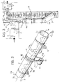
- Figure 1 is a general perspective view of a device formed according to the invention,
- Figure 2 is a schematic view, on an enlarged scale, showing, in greater detail, the operating principle of the portion of the device indicated by the arrow II in Figure 1,
- Figure 3 is a plan view of the device according to the invention, observed along the arrow III of Figure I, and
- Figures 4 to 6 are theoretical views sectioned on the life IV-IV of Figure 2, showing, in even greater detail, the general operating principle of the device according to the invention.
- In Figures 1 and 3, a device which can be used for automatically applying a coating of loose material, typically constituted by an edible, granular material, to articles constituted, for example, by food products P, is generally indicated 1.
- The products P may be constituted, for example, by products comprising spherical wafer casings with creamy and pasty fillings covered by a thin layer of chocolate or of a similar alimentary cream. A granular food product such as, for example, chopped hazelnuts or almonds, grated coconut, a mixture of meringue fragments, etc. is to be applied to the products as a coating material.
- The food products P flow towards the device 1 on an upstream conveyor T constituted, for example, by a motor-driven belt conveyor of a type widely known in the art in systems for the automatic packaging of food products.
- For an understanding of the invention, it suffices to record that the conveyor T supplies the device 1 with a flow of products P which advances generally from left to right with reference to the viewpoints of Figures 1 to 3.
- An output conveyor, indicated O, and structurally similar to the input conveyor T, on the other hand, is intended to pick up the coated products at the output of the device 1 and then to advance them into a cooling tunnel F (also of known type) . The adhesion of the loose coating material applied in the device 1 to the products P becomes firmer within the tunnel F. This result is usually achieved as a result of the cooling effect of the tunnel F: the products P are in fact supplied to the device 1 from a coating (covering) station in which a layer of an alimentary mass (chocolate cream, etc.) which is soft and creamy when the products P enter the device 1, is applied to the products P. The loose coating material therefore adheres to the alimentary mass which sets upon cooling in the tunnel F, anchoring the mass of coating firmly to the product P. This takes place according to general principles well-known in the art which do not therefore need to be recited herein and which, moreover, are not relevant for the purposes of an understanding of the invention.
- The main element of the device 1 is constituted by a
tubular duct 2 which is supported on the framework 3 of the device 1 so as to be generally inclined to the horizontal. - In practice, in the arrangement in which it is mounted in the device 1, the
duct 2 is generally inclined at an angle of the order of about 15° to the horizontal so as to have anupper input opening 2a and a lower output ordischarge opening 2b which is located in a generally lower position than theinput opening 2a. - A conveyor, indicated 4, typically a motor-driven belt conveyor (of known type and structurally similar to the conveyors T and O, except for its smaller size), is disposed immediately below the output end To of the conveyor T.
- As can best be seen in Figures 1 and 3, the upper pass of the conveyor 4 (which is constituted, as stated, by a motor-driven belt conveyor) extends with its direction of transportation perpendicular to the general direction of advance of the products P on the conveyor T, below the output end To. The conveyor 4 can therefore receive, on its conveyor pass, the products P which fall from the input conveyor T at the output end thereof.
- The upper conveyor pass of the conveyor 4 extends horizontally between an
input end 4a and an output end 4b, the terms "input" and "output" naturally referring to the direction of advance of the products P which fall onto the conveyor 4; from the viewpoints of Figures 1 and 3, this direction of advance is from left to right (Figure 1) and from top to bottom (Figure 3), respectively. - Both of the
ends 4a and 4b of the conveyor 4 project slightly relative to the sides of the conveyor T. In particular, the output end 4b of the conveyor 4 projects into theinput end 2a of theduct 2. The products P which fall onto the conveyor pass of the conveyor 4 from the conveyor T are thus urged by the conveyor 4 into theduct 2. The latter constitutes a kind of chute along and within which the products P supplied to theinput end 2a can fall until they emerge from thelower output end 2b. - As will be explained further below, the downward movement of the products P within the
duct 2 is not a true rolling fall. In fact, a carpet of loose coating material is fed onto theupstream end 4a of the conveyor 4 from a channel-shaped duct 6 (which is supplied according to criteria which will become clearer from the following); this is in fact the granular material used for coating the products P. - This granular material forms, on the upper conveyor pass of the conveyor 4, a carpet of a certain thickness (for example, of the order of 0.5-1 cm) onto which the products P discharged from the output end To of the conveyor T fall. The granular material in question also falls into the
duct 2 and, within the duct, forms a carpet M of loose granular material which, as it gradually slides towards theoutput end 2b, covers the lower portion of the cavity of theduct 2 according to criteria which will be described further below. It will suffice to note here that, because of the presence of the bed of granular material M on the lower portion of theduct 2, the products P do not roll/slide rapidly along theduct 2 but, on the contrary, perform a more regular downward movement. - At the
output end 2b of theduct 2 the products, indicated P', which are already coated (in the manner which will be described below) with granular material, fall into a further tubular duct 7 which is mounted in a fixed position relative to the framework 3. The duct is intended to deposit the products P on the lower end of a bucket orshovel conveyor 8 which is mounted on the framework 3 in a position beside theduct 2 and also at an inclination corresponding approximately to the inclination of theduct 2. The deposition of the products P' on theconveyor 8 is usually made more precise and secure by the positioning of a deflector orchannel 9 at the output of the duct 7. When the products P' have passed through both theduct 2 and the fixed duct 7, they are thus in the lower portion of the framework 3 at the lower end of the shovel orbucket conveyor 8. As a result of the general upward movement of the upper active pass of theconveyor 8, the coated products P' are returned to the upper portion of the device 1, near the input end of the output conveyor O. - The
conveyor 8 is also of generally known type and is comparable to the bucket or shovel conveyors currently used, for example, for transporting loose materials such as sand, coal or even granular food products. - The coated products P' which emerge from the conveyor 7 fall onto the shovels of the
conveyor 8 together with some of the bed of granular material M. The speed of operation of the device 1 is regulated - in dependence on the size of the device 1 - in coordination with the speed of operation of the conveyors T and O (number of products P per unit of time), in a manner such that two or three coated products P' fall onto each shovel of theconveyor 8. - At the upper end of the
shovel conveyor 8, the products P' fall onto a duct or inclined plane 10 having a generally perforated or grid-like structure. The duct or plane 10 is situated (see Figures 1 and 3 in combination) immediately beneath the upper output end of theshovel conveyor 8 and immediately above the channel-shaped duct 6. The products P' which are discharged from theconveyor 8 are thus retained on the duct or plane 10 and transferred thereby, usually by gravity, towards the output conveyor O. - The granular material discharged from the
conveyor 8 together with the products P', however, passes through the holes in the duct or plane 10 and falls onto the channel-shaped duct 6 so as to be transferred once more to theinput end 4a of the conveyor 4 in a general recycling arrangement. - Naturally, it is useful periodically or continuously to replenish the mass of the bed of granular material M in the channel-shaped duct 6. This is to take account of the fact that a certain fraction of the granular material adheres to the products P as a coating layer and is therefore removed from the device 1.
- This replenishment may be effected either by a periodic intervention by an operator or, possibly, by the provision of an automatically- or semiautomatically-operated hopper (not shown) above the channel-shaped duct 6 (or near the upstream end of the conveyor 4).
- The main characteristic of the device according to the invention is that the
duct 2 is not kept in a fixed position relative to the framework 3 but, on the contrary, can perform a general oscillatory rotational movement (back and forth) about its principal longitudinal axis X2 (see Figure 2). - This is usually achieved (see Figure 1 in particular) by mounting the
duct 2 on acradle 11 which is supported at the envisaged angle of inclination on the framework 3, and by providing, at the two ends of the cradle, pairs ofrollers 12 on which the outer surface of theduct 2 bears in a rolling arrangement. - The
duct 2 is rotated, for example, by a motor 13 (such as an electric motor) disposed on the framework, with apulley 14 mounted on its output shaft, which is oriented along an axis X13, parallel to the axis X2. Abelt 15 extends around this pulley and also around theduct 2. - By bringing about an oscillatory rotational movement of the
motor 15 it is thus possible to impart to theduct 2 a general rotational movement back and forth about the axis X2. - The amplitude and frequency of this oscillatory movement can be adjusted by means of the
control device 13a of the motor 13 (Figure 1); naturally this is a control device of known type, the criteria for the production and operation of which are well-known to experts in the art, and do not therefore require a detailed description herein. - Preferably, (see also the sections of Figures 4 to 6), the
duct 2 is constituted simply by a portion of tube of a material such as a plastics material suitable for contact with food products, for example, a crystalline PVC or polyethylene tube, etc. - The
duct 2 is preferably formed in a manner such that it has transparent windows or - even better - is formed wholly of a transparent material, to enable continuous inspection of the coating of the products P which takes place within theduct 2. - Again with reference to Figures 4 to 6, it can be seen that
longitudinal ribs 16 are preferably provided along the internal surface of theduct 2 and may extend along the generatrices of the duct 2 (which is cylindrical) or along helical paths, or may be of a different shape. - In order to describe the operating principle of the device according to the invention, reference may usefully be made to the sequence of drawings 4 to 6.
- It is assumed, for example, that a product P is supplied to the inlet opening 2a of the
duct 2 in the central position of Figure 4, that is, with the product P situated instantaneously in a central and symmetrical position relative to the generally arcuate, channel-shaped profile X which the bed of coating material M adopts within the duct 2 (also as a result of the continuous oscillatory movement described below). As it descends within the duct (Figure 5), the product P is exposed to the general oscillatory movement of theduct 2 back and forth about the axis X2 which causes the product P both to roll sideways relative to the channel formed by the bed M (thus moving from the central region towards the side edges thereof), and to be exposed to the effect of thrown granular material; because of the oscillatory movement of theduct 2, the material of the bed M in fact tends to be lifted and moved away from the walls of the duct 2 (particularly in the instantaneously uppermost region of the bed) in order to fall on the product P like rain. - The oscillatory nature of the movement (see Figures 5 and 6 in particular), together with the fact that the downward movement of each product P along the
duct 2 takes place within a time interval comprising several cycles of oscillations back and forth about the axis X2, causes the product P to follow a zig-zag path such as that schematically indicated K in Figure 2, within theduct 2. Various loops or bends can thus be distinguished in the downward path of the products P along theduct 2. These loops or bends correspond to the fact that, during its descent, each product P rolls along the bed M generally transversely and tangentially of the duct 2 (the terms transverse and tangential should naturally be interpreted with reference to the theoretical section planes of theduct 2 perpendicular to the axis X2). This sideways rolling movement is generally greatly predominant relative to the rolling movement which is generally very small and takes place along the generatrices of theduct 2; in effect, it may be said that, rather than rolling along theduct 2, the product P is entrained by the bed M of granular material which descends gradually along the duct. - Thus, and also because of the presence of the
ribs 16, the bed of granular material M tends, in general, to retain its position within the duct, as can be seen from a comparison of Figures 4 to 6. Naturally, as already stated, this general position-retention effect does not exclude a portion of the bed M, which may even be quite a considerable portion, being detached from the walls of theduct 2 and being thrown onto the product P, completing the coating thereof. - Moreover, in order to throw the coating material onto the products P more effectively, it has been found advantageous to bring about the oscillatory movement of the duct 2 (and hence the movement of the motor 13) fairly abruptly so that the
duct 2 reaches the limit positions of its oscillatory movement in the two senses, that is, the positions at which the sense of rotation is changed, at a fairly fast speed. Owing to the immediate stoppage of the movement, this encourages the material M to be thrown away from the wall of theduct 2 towards the products P by inertia. - Tests carried out by the Applicant have shown that, by using a
duct 2 which has an axial length of the order of 60 cm, and a diameter of about 10 cm, and which is kept inclined at an angle of the order of 15° to the horizontal, and by operating themotor 13 in a manner such as to impart to theduct 2 a rotational movement back and forth with an amplitude of about 90°, at a frequency of 100 oscillations/minute, it is possible to make the products P descend within a time interval of the order of about 3 - 4 seconds so that each product P is subjected to 100 cycles of the reversal of the movement of theduct 2 during its descent within theduct 2. - In these conditions, it has been found that the bed M extends through an angle of the order of 120° within the
duct 2, relative to the principal axis X2. With reference to products with diameters of about 20 mm covered by an alimentary cream, the invention enables a firm and compact coating to be formed without appreciable detachment of the granular material M on the output conveyor O, with a coating material M constituted by granules. In particular, the granular component included in the coating of the product has always been found, upon visual inspection, to be intact without appreciable damage by compression.
Claims (17)
- A method of coating articles (P) with a loose coating material (M) which is intended to adhere to the surfaces of the articles (P) comprising the steps of:- feeding (4, 6) the loose material (M) into a duct (2) having a principal axis- feeding (T, 4) the articles (P) to be coated into the duct (2), and- bringing about a rotational movement of the duct (2) about the principal axis (X2)characterized in that:- the loose material (M) is fed into the duct (2) so as to form a bed of the loose material (M) in the duct (2),- the articles (P) are disposed on the bed of loose material (M) whereby said rotational movement causes a rolling movement of the articles (P) on the bed (M) of loose material and the loose material of the bed (M) is thrown onto the articles (P), and in that the rotational movement is a back and forth movement.
- A method according to Claim 1, characterized in that it comprises the step of keeping the duct (2) generally inclined with an input end (2a) and an output end (2b) of the duct disposed in upper and lower positions relative to each other, respectively, so that, during the rotational movement of the duct (2) about the principal axis (X2), the articles (P) also perform a forward movement in the duct (2) from the input end (2a) towards the output end (2b).
- A method according to one of Claims 1 or 2, characterized in that it comprises the step of regulating the quantity of the loose material (M) in the bed in a manner such that, in use, the bed (M) extends over an angular portion of the duct (2) of the order of 120° with reference to the principal longitudinal axis (X2).
- A method according to Claim 2 and Claim 3, characterized in that the back and forth angular movement has an amplitude of about 90°.
- A method according to Claim 1 or Claim 4, characterized in that the back and forth movement is brought about at a frequency of the order of 100 cycles/minute.
- A method according to any one of Claims 1 to 5 characterized in that the duct (2) is produced in the form of a tubular duct.
- A method according to any one of Claims 1 to 6, characterized in that it comprises the step of providing longitudinal ribs (16) on the internal wall of the duct (2) for achieving a certain entrainment effect on the material of the bed (M) during the rotational movement.
- A method according to any one of Claims 1 to 7, characterized in that it comprises the step of forming the duct (2) with at least partially transparent walls.
- A method according to any one of Claims 1 to 8, characterized in that it also comprises the steps of:- picking up the articles (P') coated with the loose material and the material of the bed (M) at the output (2b) of the duct (2),- subjecting the articles (P') and the material of the bed (M) to a screening action (10) so as to separate the coated articles (P') from the material of the bed (M) in order to return the material into the duct (2).
- A device for coating articles (P) with a loose coating material (M) which is intended to adhere to the surfaces of the articles (P), comprising:- a duct (2) having a principal axis (X2) and defining a path (K) of advance of the articles (P),- supply means (4, 6) for feeding the loose material (M) into the duct (2),- further supply means (T, 4) for feeding the articles (P) to be coated into the duct (2), and- motor means (13, 14) acting on the duct in order to bring about a rotational movement of the duct (2) about the principal axis (X2)characterized in that:- said supply means (4, 6) are arranged in order to feed, in use, the loose material into the duct (2) so as to form a bed of the loose material (M) in the duct (2),- said further supply means (T, 4) feed the articles on the bed of loose material (M) and- the motor means (13, 14) impart in use a back and forth rotational movement to the duct (2) so as to bring about a rolling movement of the articles (P) on the bed (M) of loose material, and to throw the loose material of the bed (M) onto the articles (P).
- A device according to Claim 10, characterized in that it comprises a support structure (3, 11, 12) for keeping the duct (2) generally inclined with an input end (2a), associated with the further supply means (T, 4), and an output end (2b) of the duct, which are disposed in upper and lower positions relative to each other, respectively, so that, during the rotational movement of the duct (2) brought about by the motor means (13, 14), the articles (P) also perform a forward movement in the duct (2) from the input end (2a) towards the output end (2b).
- A device according to Claim 10, characterized in that the motor means (13, 14) are arranged in order to impart to the duct (2) an oscillatory angular movement having an amplitude of about 90°.
- A device according to Claim 10 or Claim 12, characterized in that the motor means (13, 14) bring about the back and forth rotational movement of the duct (2) at a frequency of the order of 100 cycles/minute.
- A device according to any one of Claims 10 to 13, characterized in that the duct (2) is tubular.
- A device according to any one of Claims 10 to 14, characterized in that the internal wall of the duct (2) has longitudinal ribs (16) for achieving a certain entrainment effect on the material of the bed (M) during the rotational movement.
- A device according to any one of Claims 10 to 15, characterized in that the duct (2) has at least partially transparent walls.
- A device according to any one of Claims 10 to 16, characterized in that it also comprises:- conveyor means (7, 8, 9) associated with the output (2b) of the duct (2) for picking up the articles (P') coated with the loose material and the material (M) of the bed,- screening means (10) associated with the conveyor means (8) for receiving the coated articles (P') and the material of the bed (M) and separating the coated articles (P') from the material of the bed (M), and- recycling means (6) for returning the material of the bed (M), from which the coated articles (P') are separated, from the screening means (10) to the supply means (4).
Applications Claiming Priority (2)
| Application Number | Priority Date | Filing Date | Title |
|---|---|---|---|
| CH466/93 | 1993-02-12 | ||
| CH00466/93A CH688809A5 (en) | 1993-02-12 | 1993-02-12 | Method and device for coating articles with a loose coating material. |
Publications (3)
| Publication Number | Publication Date |
|---|---|
| EP0610840A2 EP0610840A2 (en) | 1994-08-17 |
| EP0610840A3 EP0610840A3 (en) | 1994-08-31 |
| EP0610840B1 true EP0610840B1 (en) | 1997-05-07 |
Family
ID=4187661
Family Applications (1)
| Application Number | Title | Priority Date | Filing Date |
|---|---|---|---|
| EP94101791A Expired - Lifetime EP0610840B1 (en) | 1993-02-12 | 1994-02-07 | A method and a device for coating articles with a loose coating material |
Country Status (8)
| Country | Link |
|---|---|
| EP (1) | EP0610840B1 (en) |
| AT (1) | ATE152582T1 (en) |
| CH (1) | CH688809A5 (en) |
| DE (1) | DE69403000T2 (en) |
| DK (1) | DK0610840T3 (en) |
| ES (1) | ES2104198T3 (en) |
| GR (1) | GR3024264T3 (en) |
| SG (1) | SG49997A1 (en) |
Families Citing this family (4)
| Publication number | Priority date | Publication date | Assignee | Title |
|---|---|---|---|---|
| KR100436962B1 (en) * | 2002-08-21 | 2004-06-23 | 정창옥 | Coating device for coating eatable fragment on cake |
| KR20050020847A (en) * | 2003-08-22 | 2005-03-04 | 김득환 | Method and equipment for manufacturing Korean traditional cookies |
| IT1392568B1 (en) | 2008-12-24 | 2012-03-09 | Soremartec Sa | METHOD AND MACHINE FOR CONTINUOUS COATING OF SOURCES OF PRODUCTS, IN PARTICULAR, SWEET PRODUCTS |
| WO2022094194A1 (en) * | 2020-10-30 | 2022-05-05 | Cfa Properties, Inc. | Automated food coating system |
Family Cites Families (3)
| Publication number | Priority date | Publication date | Assignee | Title |
|---|---|---|---|---|
| US2970563A (en) * | 1957-10-16 | 1961-02-07 | Dca Food Ind | Coating apparatus for comestibles |
| GB972904A (en) * | 1964-05-10 | 1964-10-21 | Dca Food Ind | Improvements relating to comestible coating equipment |
| US3381658A (en) * | 1966-01-04 | 1968-05-07 | Franchetts Crullers Inc | Apparatus for sugar coating doughnuts |
-
1993
- 1993-02-12 CH CH00466/93A patent/CH688809A5/en not_active IP Right Cessation
-
1994
- 1994-02-07 ES ES94101791T patent/ES2104198T3/en not_active Expired - Lifetime
- 1994-02-07 AT AT94101791T patent/ATE152582T1/en not_active IP Right Cessation
- 1994-02-07 DK DK94101791.5T patent/DK0610840T3/en active
- 1994-02-07 DE DE69403000T patent/DE69403000T2/en not_active Expired - Fee Related
- 1994-02-07 SG SG1996012352A patent/SG49997A1/en unknown
- 1994-02-07 EP EP94101791A patent/EP0610840B1/en not_active Expired - Lifetime
-
1997
- 1997-07-30 GR GR970401912T patent/GR3024264T3/en unknown
Also Published As
| Publication number | Publication date |
|---|---|
| SG49997A1 (en) | 1998-06-15 |
| DE69403000D1 (en) | 1997-06-12 |
| ES2104198T3 (en) | 1997-10-01 |
| EP0610840A3 (en) | 1994-08-31 |
| DE69403000T2 (en) | 1997-09-11 |
| ATE152582T1 (en) | 1997-05-15 |
| GR3024264T3 (en) | 1997-10-31 |
| EP0610840A2 (en) | 1994-08-17 |
| CH688809A5 (en) | 1998-04-15 |
| DK0610840T3 (en) | 1997-06-09 |
Similar Documents
| Publication | Publication Date | Title |
|---|---|---|
| US4907720A (en) | Method and apparatus for uniformly dispensing a seasoning material | |
| US3988875A (en) | Apparatus for producing and packaging food chips | |
| EP0411174B1 (en) | Distribution device for coating foodstuffs | |
| US6635292B2 (en) | Ultrasonic rotary forming of food products | |
| US4808424A (en) | Process for coating foodstuffs with particulate material | |
| AU2002342154A1 (en) | Ultrasonic rotary forming of food products | |
| EP0610840A2 (en) | A method and a device for coating articles with a loose coating material | |
| JP4295622B2 (en) | Flowable solid dispensing device and method of use | |
| US4304326A (en) | Apparatus and method for transforming a multiple layered bed of pieces into a thinner layer | |
| JP3691541B2 (en) | Conveying device in crop sorting device | |
| JP3397893B2 (en) | Crushed ice chip conveyor | |
| EP1675472B1 (en) | Machine for decorating a food product, in particular a cake, with an ingredient in granular form | |
| US20020148364A1 (en) | Apparatus for depositing granular food products on moving elements | |
| JPS6348495B2 (en) | ||
| JPH05221519A (en) | Bar-like tool feeder for kneaded product | |
| US4962699A (en) | Distributing apparatus | |
| GB2317322A (en) | A biscuit manufacturing process | |
| FR2683214A1 (en) | Device serving for dispensing specific metered amounts of a product | |
| US4304085A (en) | Cocktail filling machine and method | |
| US2674100A (en) | Conveying of pieces of material through a zone of refrigeration | |
| JPH09224544A (en) | Powder sticking method for lumped food and powder sticking device used for the same | |
| CA2000218A1 (en) | Method and apparatus for aligning elongated articles | |
| US20080220142A1 (en) | Process for Producing an Aerated Granulated Foodstuff, and Corresponding Product and Device | |
| JP2005206196A (en) | Raw material supply equipment for automatic packaging machines | |
| JPH06115673A (en) | feeder |
Legal Events
| Date | Code | Title | Description |
|---|---|---|---|
| PUAI | Public reference made under article 153(3) epc to a published international application that has entered the european phase |
Free format text: ORIGINAL CODE: 0009012 |
|
| PUAL | Search report despatched |
Free format text: ORIGINAL CODE: 0009013 |
|
| AK | Designated contracting states |
Kind code of ref document: A2 Designated state(s): AT BE CH DE DK ES FR GB GR IE IT LI LU MC NL PT SE |
|
| AK | Designated contracting states |
Kind code of ref document: A3 Designated state(s): AT BE CH DE DK ES FR GB GR IE IT LI LU MC NL PT SE |
|
| RAP1 | Party data changed (applicant data changed or rights of an application transferred) |
Owner name: FERRERO OFFENE HANDELSGESELLSCHAFT M.B.H. Owner name: FERRERO S.P.A. Owner name: SOREMARTEC S.A. |
|
| 17P | Request for examination filed |
Effective date: 19941126 |
|
| 17Q | First examination report despatched |
Effective date: 19950509 |
|
| GRAG | Despatch of communication of intention to grant |
Free format text: ORIGINAL CODE: EPIDOS AGRA |
|
| GRAH | Despatch of communication of intention to grant a patent |
Free format text: ORIGINAL CODE: EPIDOS IGRA |
|
| GRAH | Despatch of communication of intention to grant a patent |
Free format text: ORIGINAL CODE: EPIDOS IGRA |
|
| GRAA | (expected) grant |
Free format text: ORIGINAL CODE: 0009210 |
|
| AK | Designated contracting states |
Kind code of ref document: B1 Designated state(s): AT BE CH DE DK ES FR GB GR IE IT LI LU MC NL PT SE |
|
| REF | Corresponds to: |
Ref document number: 152582 Country of ref document: AT Date of ref document: 19970515 Kind code of ref document: T |
|
| REG | Reference to a national code |
Ref country code: CH Ref legal event code: EP |
|
| ITF | It: translation for a ep patent filed | ||
| REG | Reference to a national code |
Ref country code: CH Ref legal event code: NV Representative=s name: JACOBACCI & PERANI S.A. |
|
| REG | Reference to a national code |
Ref country code: DK Ref legal event code: T3 |
|
| REF | Corresponds to: |
Ref document number: 69403000 Country of ref document: DE Date of ref document: 19970612 |
|
| ET | Fr: translation filed | ||
| REG | Reference to a national code |
Ref country code: IE Ref legal event code: FG4D Free format text: 73792 |
|
| REG | Reference to a national code |
Ref country code: GR Ref legal event code: FG4A Free format text: 3024264 |
|
| REG | Reference to a national code |
Ref country code: ES Ref legal event code: FG2A Ref document number: 2104198 Country of ref document: ES Kind code of ref document: T3 |
|
| PLBE | No opposition filed within time limit |
Free format text: ORIGINAL CODE: 0009261 |
|
| STAA | Information on the status of an ep patent application or granted ep patent |
Free format text: STATUS: NO OPPOSITION FILED WITHIN TIME LIMIT |
|
| 26N | No opposition filed | ||
| PGFP | Annual fee paid to national office [announced via postgrant information from national office to epo] |
Ref country code: MC Payment date: 20000118 Year of fee payment: 7 |
|
| PGFP | Annual fee paid to national office [announced via postgrant information from national office to epo] |
Ref country code: SE Payment date: 20010109 Year of fee payment: 8 |
|
| PGFP | Annual fee paid to national office [announced via postgrant information from national office to epo] |
Ref country code: AT Payment date: 20010110 Year of fee payment: 8 |
|
| PGFP | Annual fee paid to national office [announced via postgrant information from national office to epo] |
Ref country code: DK Payment date: 20010112 Year of fee payment: 8 |
|
| PGFP | Annual fee paid to national office [announced via postgrant information from national office to epo] |
Ref country code: IE Payment date: 20010118 Year of fee payment: 8 |
|
| PGFP | Annual fee paid to national office [announced via postgrant information from national office to epo] |
Ref country code: CH Payment date: 20010122 Year of fee payment: 8 |
|
| PGFP | Annual fee paid to national office [announced via postgrant information from national office to epo] |
Ref country code: PT Payment date: 20010123 Year of fee payment: 8 |
|
| PGFP | Annual fee paid to national office [announced via postgrant information from national office to epo] |
Ref country code: GR Payment date: 20010129 Year of fee payment: 8 Ref country code: NL Payment date: 20010129 Year of fee payment: 8 |
|
| PGFP | Annual fee paid to national office [announced via postgrant information from national office to epo] |
Ref country code: LU Payment date: 20010205 Year of fee payment: 8 |
|
| PG25 | Lapsed in a contracting state [announced via postgrant information from national office to epo] |
Ref country code: MC Free format text: LAPSE BECAUSE OF NON-PAYMENT OF DUE FEES Effective date: 20010228 |
|
| REG | Reference to a national code |
Ref country code: GB Ref legal event code: IF02 |
|
| PG25 | Lapsed in a contracting state [announced via postgrant information from national office to epo] |
Ref country code: LU Free format text: LAPSE BECAUSE OF NON-PAYMENT OF DUE FEES Effective date: 20020207 Ref country code: IE Free format text: LAPSE BECAUSE OF NON-PAYMENT OF DUE FEES Effective date: 20020207 Ref country code: AT Free format text: LAPSE BECAUSE OF NON-PAYMENT OF DUE FEES Effective date: 20020207 |
|
| PG25 | Lapsed in a contracting state [announced via postgrant information from national office to epo] |
Ref country code: SE Free format text: LAPSE BECAUSE OF NON-PAYMENT OF DUE FEES Effective date: 20020208 |
|
| PG25 | Lapsed in a contracting state [announced via postgrant information from national office to epo] |
Ref country code: LI Free format text: LAPSE BECAUSE OF NON-PAYMENT OF DUE FEES Effective date: 20020228 Ref country code: DK Free format text: LAPSE BECAUSE OF NON-PAYMENT OF DUE FEES Effective date: 20020228 Ref country code: CH Free format text: LAPSE BECAUSE OF NON-PAYMENT OF DUE FEES Effective date: 20020228 |
|
| PG25 | Lapsed in a contracting state [announced via postgrant information from national office to epo] |
Ref country code: PT Free format text: LAPSE BECAUSE OF NON-PAYMENT OF DUE FEES Effective date: 20020831 |
|
| PG25 | Lapsed in a contracting state [announced via postgrant information from national office to epo] |
Ref country code: NL Free format text: LAPSE BECAUSE OF NON-PAYMENT OF DUE FEES Effective date: 20020901 |
|
| PG25 | Lapsed in a contracting state [announced via postgrant information from national office to epo] |
Ref country code: GR Free format text: LAPSE BECAUSE OF NON-PAYMENT OF DUE FEES Effective date: 20020909 |
|
| EUG | Se: european patent has lapsed |
Ref document number: 94101791.5 |
|
| REG | Reference to a national code |
Ref country code: CH Ref legal event code: PL |
|
| REG | Reference to a national code |
Ref country code: DK Ref legal event code: EBP |
|
| NLV4 | Nl: lapsed or anulled due to non-payment of the annual fee |
Effective date: 20020901 |
|
| REG | Reference to a national code |
Ref country code: PT Ref legal event code: MM4A Free format text: LAPSE DUE TO NON-PAYMENT OF FEES Effective date: 20020831 |
|
| REG | Reference to a national code |
Ref country code: IE Ref legal event code: MM4A |
|
| PGFP | Annual fee paid to national office [announced via postgrant information from national office to epo] |
Ref country code: ES Payment date: 20071228 Year of fee payment: 15 |
|
| PGFP | Annual fee paid to national office [announced via postgrant information from national office to epo] |
Ref country code: IT Payment date: 20080212 Year of fee payment: 15 Ref country code: GB Payment date: 20080118 Year of fee payment: 15 Ref country code: DE Payment date: 20080221 Year of fee payment: 15 |
|
| PGFP | Annual fee paid to national office [announced via postgrant information from national office to epo] |
Ref country code: FR Payment date: 20080229 Year of fee payment: 15 |
|
| PGFP | Annual fee paid to national office [announced via postgrant information from national office to epo] |
Ref country code: BE Payment date: 20080208 Year of fee payment: 15 |
|
| BERE | Be: lapsed |
Owner name: S.A. *SOREMARTEC Effective date: 20090228 |
|
| GBPC | Gb: european patent ceased through non-payment of renewal fee |
Effective date: 20090207 |
|
| REG | Reference to a national code |
Ref country code: FR Ref legal event code: ST Effective date: 20091030 |
|
| PG25 | Lapsed in a contracting state [announced via postgrant information from national office to epo] |
Ref country code: DE Free format text: LAPSE BECAUSE OF NON-PAYMENT OF DUE FEES Effective date: 20090901 |
|
| PG25 | Lapsed in a contracting state [announced via postgrant information from national office to epo] |
Ref country code: BE Free format text: LAPSE BECAUSE OF NON-PAYMENT OF DUE FEES Effective date: 20090228 |
|
| REG | Reference to a national code |
Ref country code: ES Ref legal event code: FD2A Effective date: 20090209 |
|
| PG25 | Lapsed in a contracting state [announced via postgrant information from national office to epo] |
Ref country code: GB Free format text: LAPSE BECAUSE OF NON-PAYMENT OF DUE FEES Effective date: 20090207 Ref country code: FR Free format text: LAPSE BECAUSE OF NON-PAYMENT OF DUE FEES Effective date: 20090302 |
|
| PG25 | Lapsed in a contracting state [announced via postgrant information from national office to epo] |
Ref country code: ES Free format text: LAPSE BECAUSE OF NON-PAYMENT OF DUE FEES Effective date: 20090209 |
|
| PG25 | Lapsed in a contracting state [announced via postgrant information from national office to epo] |
Ref country code: IT Free format text: LAPSE BECAUSE OF NON-PAYMENT OF DUE FEES Effective date: 20090207 |