EP0610757A2 - Fully enclosed electrical engine with at least one internal fan - Google Patents
Fully enclosed electrical engine with at least one internal fan Download PDFInfo
- Publication number
- EP0610757A2 EP0610757A2 EP94101299A EP94101299A EP0610757A2 EP 0610757 A2 EP0610757 A2 EP 0610757A2 EP 94101299 A EP94101299 A EP 94101299A EP 94101299 A EP94101299 A EP 94101299A EP 0610757 A2 EP0610757 A2 EP 0610757A2
- Authority
- EP
- European Patent Office
- Prior art keywords
- machine
- fan
- guide plate
- internal fan
- stator
- Prior art date
- Legal status (The legal status is an assumption and is not a legal conclusion. Google has not performed a legal analysis and makes no representation as to the accuracy of the status listed.)
- Granted
Links
- 238000001816 cooling Methods 0.000 claims abstract description 24
- 230000002093 peripheral effect Effects 0.000 claims description 3
- 241001484259 Lacuna Species 0.000 abstract 1
- 238000004804 winding Methods 0.000 description 6
- 230000002349 favourable effect Effects 0.000 description 3
- 230000017525 heat dissipation Effects 0.000 description 1
- 230000005855 radiation Effects 0.000 description 1
- 238000009423 ventilation Methods 0.000 description 1
Images

Classifications
-
- F—MECHANICAL ENGINEERING; LIGHTING; HEATING; WEAPONS; BLASTING
- F04—POSITIVE - DISPLACEMENT MACHINES FOR LIQUIDS; PUMPS FOR LIQUIDS OR ELASTIC FLUIDS
- F04D—NON-POSITIVE-DISPLACEMENT PUMPS
- F04D25/00—Pumping installations or systems
- F04D25/02—Units comprising pumps and their driving means
- F04D25/08—Units comprising pumps and their driving means the working fluid being air, e.g. for ventilation
- F04D25/082—Units comprising pumps and their driving means the working fluid being air, e.g. for ventilation the unit having provision for cooling the motor
-
- F—MECHANICAL ENGINEERING; LIGHTING; HEATING; WEAPONS; BLASTING
- F04—POSITIVE - DISPLACEMENT MACHINES FOR LIQUIDS; PUMPS FOR LIQUIDS OR ELASTIC FLUIDS
- F04D—NON-POSITIVE-DISPLACEMENT PUMPS
- F04D29/00—Details, component parts, or accessories
- F04D29/58—Cooling; Heating; Diminishing heat transfer
- F04D29/5806—Cooling the drive system
-
- H—ELECTRICITY
- H02—GENERATION; CONVERSION OR DISTRIBUTION OF ELECTRIC POWER
- H02K—DYNAMO-ELECTRIC MACHINES
- H02K9/00—Arrangements for cooling or ventilating
- H02K9/10—Arrangements for cooling or ventilating by gaseous cooling medium flowing in closed circuit, a part of which is external to the machine casing
Definitions
- the invention relates to a closed electrical machine with at least one internal fan.
- the heat is dissipated via the machine surface through free convection and radiation.
- the amount of heat given off and thus also the performance of the machine are determined by the surface of the housing that is effective for the heat given off.
- the invention is based on the object of designing a closed electrical machine with at least one internal fan in such a way that the heat emission is increased in the latter and thus a higher output is possible with the same machine size.
- the improved cooling can be used with particular advantage in a machine in which pronounced poles are provided in the stator and pole gaps lying between them, and in which the guide plate has openings in the area opposite the pole gaps.
- flow openings for an axial cooling air flow result from the pole gaps existing between them.
- the air flow generated by the internal fan is directed to the pole gaps by the openings of the guide plate opposite the pole gaps.
- the poles are covered by the baffle against the air flow. This avoids an air short circuit and the entire air flow is concentrated on the pole gaps.
- the flow conditions in the machine according to the invention can still be improved by designing the machine according to the features of claims 4 and 5.
- reverse flows of the cooling air in the region of the radial fan are counteracted.
- the part of the guide plate which directs the air flow to the flow openings is favorable to the air flow deflected on the housing, so that the flow losses are reduced.
- the rotor 2 is provided with a rotor winding 3 and the stator 4 with main pole windings 5 and with reversing pole windings 7 arranged in the pole gaps 6 between the main pole windings 5.
- a radial fan 9 is mounted on the shaft 8 of the rotor 2 as an internal fan of the machine.
- a baffle 10 is arranged, which is held clamped with its peripheral edge 11 between the end edge of the machine housing 12 and the bearing plate 13 attached to this machine.
- the baffle plate 10 has a part 14 which points obliquely away from the peripheral edge 11 parallel to the end edge of the machine housing 12 and in which openings 15 are formed.
- the diagonally pointing part 14 is adjoined by a contour that runs parallel to the contour of the radial fan 9 and radially overlaps the contour of the radial fan 9 Part 16.
- the radial fan 9 has a contour which runs obliquely from its inner end face 17 to its outer periphery 18. Accordingly, the overlapping part 16 of the guide plate 10 is also designed to run obliquely.
- the distance between the fan blades and the overlapping part should be in the range of 2-6 mm in order to effectively prevent backflow.
- cooling channels 20 are provided as flow openings in the area between the slots 19 receiving the rotor winding 3 and the shaft 8.
- the cooling air flowing through the pole gaps 6 from the fan side of the machine to the opposite machine side can flow back to the fan side through these cooling channels 20.
- the radial arrangement of the cooling channels 20 lies in the suction area of the radial fan 9, so that favorable flow conditions result.
- the cooling air conveyed radially outward by the radial fan 9 flows against the corresponding end shield 13 of the machine, whereby it emits heat to it and is not steered.
- the cooling air then flows, as indicated by arrows 21, through the openings 15 of the guide plate 10.
- these openings 15 lie in front of the pole gaps 6 of the machine, so that the cooling air after passing through the openings 15 in the pole gaps 6 arrives and flows through them to the other machine side. From the other side of the machine, the cooling air flows back through the cooling channels 20 of the rotor 2 to the radial fan 9, so that the circuit is closed.
- the cooling air on the other side of the machine comes into contact with the parts of the machine housing located there, in particular the bearing plate there, and outputs the main and reversing pole windings 5 and 7 in the pole gaps 6 Heat to the machine housing.
- the cooling air flows around and cools the commutator located on this other machine side.
- the arrangement of the guide plate 10 and the alignment of its openings 15 on the pole gaps 6 enables the desired guidance of the cooling air flow. This targeted routing of the cooling air flow leads to a significantly improved cooling of the machine, which enables a corresponding increase in performance.
- a performance increase of over 30% compared to the performance of a machine without a baffle 10 is achieved.
Landscapes
- Engineering & Computer Science (AREA)
- Mechanical Engineering (AREA)
- General Engineering & Computer Science (AREA)
- Physics & Mathematics (AREA)
- Thermal Sciences (AREA)
- Power Engineering (AREA)
- Motor Or Generator Cooling System (AREA)
Abstract
Description
Die Erfindung betrifft eine geschlossene elektrische Maschine mit mindestens einem Innenlüfter.The invention relates to a closed electrical machine with at least one internal fan.
Bei geschlossenen elektrischen Maschinen ohne Oberflächenbelüftung erfolgt die Wärmeabgabe über die Maschinenoberfläche durch freie Konvexion und Strahlung. Die Höhe der Wärmeabgabe und damit auch die Leistungsgröße der Maschine werden durch deren für die Wärmeabgabe wirksame Gehäuseoberfläche bestimmt. Um die vor allem im Maschineninneren entstehende Verlustwärme effektiver an das Gehäuse zu übertragen, ist es bekannt, Lufterräder oder sonstige, eine Luftbewegung erzeugende Teile vorzusehen. Infolge dieser Luftbewegung gelangt erwärmte Luft zum Gehäuse. Durch eine derartige Luftverwirbelung läßt sich die Wärmeabgabe der Maschine jedoch nur unwesentlich steigern.In the case of closed electrical machines without surface ventilation, the heat is dissipated via the machine surface through free convection and radiation. The amount of heat given off and thus also the performance of the machine are determined by the surface of the housing that is effective for the heat given off. In order to transfer the heat loss that arises particularly inside the machine more effectively to the housing, it is known to provide air wheels or other parts that generate air movement. As a result of this air movement, heated air reaches the housing. Such a swirling of air can only increase the heat dissipation of the machine insignificantly.
Der Erfindung liegt die Aufgabe zugrunde, eine geschlossene elektrische Maschine mit mindestens einem Innenlüfter so auszubilden, daß bei dieser die Wärmeabgabe gesteigert und somit eine größere Leistung bei gleicher Maschinengröße möglich ist.The invention is based on the object of designing a closed electrical machine with at least one internal fan in such a way that the heat emission is increased in the latter and thus a higher output is possible with the same machine size.
Eine diese Anforderungen erfüllende Maschine wird im Anspruch 1 beschrieben. Mit Hilfe des Leitbleches wird bei dieser Maschine der Abluftstrom des Innenlüfters gezielt zu den Strömungsöffnungen des Ständers gelenkt, so daß dieser Luftstrom dann durch diese Strömungsöffnungen hindurch zur anderen Seite der Maschine strömt. Damit wird aber auch eine intensive Rückströmung durch die im Läufer vorgesehenen Strömungsöffnungen bewirkt. Infolge der intensiven Durchströmung von Läufer und Ständer wird die in diesen Maschinenteilen anfallende Verlustwärme besser abgeführt und an das Gehäuse abgegeben.A machine that meets these requirements is described in
Mit besonderem Vorteil läßt sich die verbesserte Kühlung bei einer Maschine anwenden, bei der im Ständer ausgeprägte Pole und zwischen diesen liegende Pollücken vorgesehen sind, und bei der das Leitblech jeweils in dem den Pollücken gegenüberliegenden Bereich Durchbrüche aufweist. Bei Maschinen mit ausgeprägten Polen ergeben sich durch die zwischen diesen bestehenden Pollücken Strömungsöffnungen für einen axialen Kühlluftstrom. Durch die den Pollücken gegenüberliegenden Durchbrüche des Leitbleches wird der vom Innenlüfter erzeugte Luftstrom zu den Pollücken gelenkt. Die Pole werden dagegen durch das Leitblech gegenüber dem Luftstrom abgedeckt. Damit wird ein Luftkurzschluß vermieden und der gesamte Luftstrom auf die Pollücken konzentriert.The improved cooling can be used with particular advantage in a machine in which pronounced poles are provided in the stator and pole gaps lying between them, and in which the guide plate has openings in the area opposite the pole gaps. In the case of machines with pronounced poles, flow openings for an axial cooling air flow result from the pole gaps existing between them. The air flow generated by the internal fan is directed to the pole gaps by the openings of the guide plate opposite the pole gaps. The poles, however, are covered by the baffle against the air flow. This avoids an air short circuit and the entire air flow is concentrated on the pole gaps.
Besonders günstige Strömungsverhältnisse ergeben sich bei der erfindungsgemäßen Maschine dann, wenn als Innenlüfter ein Radiallüfter vorgesehen ist, in dessen radial innenliegendem Ansaugbereich im Läufer der Maschine als Strömungsöffnungen vorgesehene Kühlkanäle münden und der in seinem Umfangsbereich von dem Leitblech in radialer Richtung überlappt ist. Entsprechend dem natürlichen Strömungsverlauf eines Radiallüfters kann dieser über die radial innenliegenden Strömungskanäle des Läufers Luft ansaugen und nach radial außen fördern. Dort wird die Luft durch das Leitblech in die Strömungsöffnungen des Ständers gelenkt. Bei einem solchen Kreislauf der Kühlluft muß diese beim Einströmen in die Strömungskanäle des Läufers gegebenenfalls an einem auf der dem Innenlüfter gegenüberliegenden Maschinenseite vorhandenen Kommutator vorbeiströmen. Damit wird bei einer mit einem Kommutator versehenen elektrischen Maschine auch noch eine intensive Kühlung des Kommutators erreicht.Particularly favorable flow conditions result in the machine according to the invention when a radial fan is provided as the internal fan, in whose radially inner suction area cooling channels provided as flow openings open in the rotor of the machine and which is circumferentially overlapped in the radial direction by the guide plate. According to the natural flow pattern of a radial fan, it can suck in air via the radially inner flow channels of the rotor and convey it radially outwards. There the air is directed through the baffle into the flow openings of the stator. In the case of such a circuit of the cooling air, it may have to flow past a commutator on the machine side opposite the internal fan when it flows into the flow channels of the rotor. With an electrical machine provided with a commutator, intensive cooling of the commutator is thus also achieved.
Die Strömungsverhältnisse lassen sich bei der erfindungsgemäßen Maschine noch durch eine Ausgestaltung derselben gemäß den Merkmalen der Ansprüche 4 und 5 verbessern. Bei einer Ausgestaltung nach Anspruch 4 wird Rückströmungen der Kühlluft im Bereich des Radiallüfters entgegengewirkt. Bei einer Ausgestaltung nach Anspruch 5 liegt der den Luftstrom zu den Strömungsöffnungen lenkende Teil des Leitbleches günstig zu dem am Gehäuse umgelenkten Luftstrom, so daß die Strömungsverluste verkleinert werden.The flow conditions in the machine according to the invention can still be improved by designing the machine according to the features of
Anhand eines in der Zeichnung dargestellten Ausführungsbeispieles wird die Erfindung nachfolgend näher beschrieben. Es zeigt:
- FIG 1
- die Lüfterseite einer elektrischen Maschine im Teillängsschnitt,
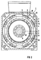
- FIG 2
- die Lüfterseite einer elektrischen Maschine im Schnitt entlang der Linie II-II in FIG 1.
- FIG. 1
- the fan side of an electrical machine in partial longitudinal section,
- FIG 2
- the fan side of an electrical machine in section along the line II-II in FIG. 1
Mit 1 ist eine Gleichstrommaschine bezeichnet, deren Läufer 2 mit einer Läuferwicklung 3 und deren Ständer 4 mit Hauptpolwicklungen 5 und mit in den zwischen den Hauptpolwicklungen 5 bestehenden Pollücken 6 angeordneten Wendepolwicklungen 7 versehen ist. Auf der Welle 8 des Läufers 2 ist ein Radiallüfter 9 als Innenlüfter der Maschine angebracht.1 with a DC machine is designated, the
In dem Raum zwischen dem Radiallüfter 9 und der betreffenden Stirnseite des Ständers 4 ist ein Leitblech 10 angeordnet, das mit seinem Umfangsrand 11 zwischen der Stirnkante des Maschinengehäuses 12 und des auf dieser Maschine angebrachten Lagerschildes 13 eingeklemmt gehalten ist. Das Leitblech 10 weist einen gegenüber dem mit der Stirnkante des Maschinengehäuses 12 parallelen Umlaufrand 11 schräg wegweisenden Teil 14 auf, in welchem Durchbrüche 15 ausgebildet sind. An den schräg wegweisenden Teil 14 schließt sich ein zur Kontur des Radiallüfters 9 parallel verlaufenden und die Kontur des Radiallüfters 9 radial überlappender Teil 16 an. Bei dem dargestellten Ausführungsbeispiel besitzt der Radiallüfter 9 eine von seiner inneren Stirnseite 17 zu seinem Außenumfang 18 hin schräg verlaufende Kontur. Dementsprechend ist auch der überlappende Teil 16 des Leitbleches 10 schräg verlaufend ausgebildet. Der Abstand zwischen den Lüfterschaufeln und dem überlappenden Teil sollte im Bereich von 2-6 mm liegen, um eine Rückströmung wirkungsvoll zu verhindern.In the space between the
Im Blechpaket des Läufers 2 sind in dem Bereich zwischen den die Läuferwicklung 3 aufnehmenden Nuten 19 und der Welle 8 Kühlkanäle 20 als Strömungsöffnungen vorgesehen. Durch diese Kühlkanäle 20 kann die durch die Pollücken 6 von der Lüfterseite der Maschine zu der gegenüberliegenden Maschinenseite geströmte Kühlluft wieder zu der Lüfterseite zurückströmen. Die Kühlkanäle 20 liegen in ihrer radialen Anordnung im Ansaugbereich des Radiallüfters 9, so daß sich günstige Strömungsverhältnisse ergeben.In the laminated core of the
Die von dem Radiallüfter 9 nach radial außen geförderte Kühlluft strömt gegen den entsprechenden Lagerschild 13 der Maschine, wobei sie Warme an diesen abgibt und ungelenkt wird. Die Kühlluft strömt dann, wie durch Pfeile 21 angedeutet, durch die Durchbrüche 15 des Leitbleches 10. Wie aus der FIG 2 erkennbar ist, liegen diese Durchbrüche 15 vor den Pollücken 6 der Maschine, so daß die Kühlluft nach dem Durchtritt durch die Durchbrüche 15 in die Pollücken 6 gelangt und diese zur anderen Maschinenseite hin durchströmt. Von der anderen Maschinenseite strömt die Kühlluft wieder über die Kühlkanäle 20 des Läufers 2 zum Radiallüfter 9 zurück, so daß der Kreislauf geschlossen ist.The cooling air conveyed radially outward by the
Nach dem Durchströmen der Pollücken 6 kommt die Kühlluft auf der anderen Maschinenseite mit den dort befindlichen Teilen des Maschinengehäuses, insbesondere dem dortigen Lagerschild in Berührung und gibt die in den Pollücken 6 von den Haupt- und Wendepolwicklungen 5 und 7 aufgenommene Wärme an das Maschinengehäuse ab. Außerdem umströmt die Kühlluft den auf dieser anderen Maschinenseite befindlichen Kommutator und kühlt diesen. Durch die Anordnung des Leitbleches 10 und die Ausrichtung von dessen Durchbrüchen 15 auf die Pollücken 6 gelingt die gewünschte Führung des Kühlluftstromes. Diese gezielte Führung des Kühlluftstromes führt zu einer wesentlich verbesserten Kühlung der Maschine, die eine entsprechende Leistungssteigerung ermöglicht. So wird in Abhängigkeit von der Drehzahl der Maschine eine Leistungssteigerung von über 30 % gegenüber der Leistung einer Maschine ohne Leitblech 10 erreicht.After flowing through the
Claims (5)
Applications Claiming Priority (2)
| Application Number | Priority Date | Filing Date | Title |
|---|---|---|---|
| DE4303940 | 1993-02-10 | ||
| DE4303940 | 1993-02-10 |
Publications (3)
| Publication Number | Publication Date |
|---|---|
| EP0610757A2 true EP0610757A2 (en) | 1994-08-17 |
| EP0610757A3 EP0610757A3 (en) | 1994-09-21 |
| EP0610757B1 EP0610757B1 (en) | 1996-09-25 |
Family
ID=6480112
Family Applications (1)
| Application Number | Title | Priority Date | Filing Date |
|---|---|---|---|
| EP94101299A Revoked EP0610757B1 (en) | 1993-02-10 | 1994-01-28 | Fully enclosed electrical engine with at least one internal fan |
Country Status (2)
| Country | Link |
|---|---|
| EP (1) | EP0610757B1 (en) |
| DE (1) | DE59400708D1 (en) |
Cited By (3)
| Publication number | Priority date | Publication date | Assignee | Title |
|---|---|---|---|---|
| US5905318A (en) * | 1997-06-03 | 1999-05-18 | Frankl & Kirchner Gmbh & Co. Kg Fabrik Fur Elektromotoren U. Elektrische Apparate | Electric motor |
| US9863435B2 (en) | 2013-12-11 | 2018-01-09 | Fanuc Corporation | Fan unit including vibration suppressing structure and electric motor |
| EP3393014A1 (en) * | 2017-04-20 | 2018-10-24 | Siemens Aktiengesellschaft | Rotor end ring for a rotor of an electric rotation machine |
Citations (3)
| Publication number | Priority date | Publication date | Assignee | Title |
|---|---|---|---|---|
| GB681419A (en) * | 1950-04-11 | 1952-10-22 | British Thomson Houston Co Ltd | Improvements in and relating to dynamo-electric machines |
| US2970233A (en) * | 1958-01-07 | 1961-01-31 | Westinghouse Electric Corp | Ventilating system for a dynamo-electric machine |
| EP0261295A1 (en) * | 1986-08-22 | 1988-03-30 | S.A. Acec Transport | Self-cooled electrical motor |
-
1994
- 1994-01-28 DE DE59400708T patent/DE59400708D1/en not_active Revoked
- 1994-01-28 EP EP94101299A patent/EP0610757B1/en not_active Revoked
Patent Citations (3)
| Publication number | Priority date | Publication date | Assignee | Title |
|---|---|---|---|---|
| GB681419A (en) * | 1950-04-11 | 1952-10-22 | British Thomson Houston Co Ltd | Improvements in and relating to dynamo-electric machines |
| US2970233A (en) * | 1958-01-07 | 1961-01-31 | Westinghouse Electric Corp | Ventilating system for a dynamo-electric machine |
| EP0261295A1 (en) * | 1986-08-22 | 1988-03-30 | S.A. Acec Transport | Self-cooled electrical motor |
Cited By (4)
| Publication number | Priority date | Publication date | Assignee | Title |
|---|---|---|---|---|
| US5905318A (en) * | 1997-06-03 | 1999-05-18 | Frankl & Kirchner Gmbh & Co. Kg Fabrik Fur Elektromotoren U. Elektrische Apparate | Electric motor |
| US9863435B2 (en) | 2013-12-11 | 2018-01-09 | Fanuc Corporation | Fan unit including vibration suppressing structure and electric motor |
| EP3393014A1 (en) * | 2017-04-20 | 2018-10-24 | Siemens Aktiengesellschaft | Rotor end ring for a rotor of an electric rotation machine |
| WO2018192704A1 (en) * | 2017-04-20 | 2018-10-25 | Siemens Aktiengesellschaft | Rotor end ring for a rotor of an electric rotating machine |
Also Published As
| Publication number | Publication date |
|---|---|
| EP0610757A3 (en) | 1994-09-21 |
| DE59400708D1 (en) | 1996-10-31 |
| EP0610757B1 (en) | 1996-09-25 |
Similar Documents
| Publication | Publication Date | Title |
|---|---|---|
| DE102008064495B3 (en) | Electric machine with several cooling streams and cooling process | |
| DE19956918C2 (en) | Electrical machine | |
| DE2655753A1 (en) | COMMUTATOR MOTOR | |
| EP0574731A1 (en) | Hand-held machine tool with ventilated motor | |
| DE4003155A1 (en) | ELECTRIC MACHINE WITH FOREIGN VENTILATION | |
| EP0342554A1 (en) | Liquid-cooled electric machine | |
| DE112016002202T5 (en) | Electric rotary machine | |
| DE1939184A1 (en) | Arrangement for cooling the rotors of electrical machines, in particular small electric motors | |
| DE2334637B2 (en) | Pass-through ventilated electric machine | |
| DE4443427C2 (en) | Electrical machine | |
| EP2730010A1 (en) | Electric motor | |
| DE29700643U1 (en) | Cooling concept for an electric drive system | |
| DE102015000536B4 (en) | Electric machine and motor vehicle | |
| DE19549204C2 (en) | Electrical machine, in particular three-phase generator | |
| EP0610757B1 (en) | Fully enclosed electrical engine with at least one internal fan | |
| DE102014117962A1 (en) | Electric drive system with improved cooling | |
| EP0585644B1 (en) | Totally enclosed liquid-cooled, fully enclosed electrical engine | |
| EP1516109B1 (en) | Device for cooling a current generator unit | |
| EP2888804B1 (en) | Electric machine and method for cooling an electric machine | |
| CH648439A5 (en) | Rotating electrical machine having a stator with radially arranged cooling channels with spacer webs | |
| EP0849858B1 (en) | Electric air-cooled machine | |
| DE2558405C3 (en) | Closed, surface-ventilated electrical machine | |
| DE10225221B4 (en) | Ventilation of a ring motor for a tube mill | |
| DE69800036T2 (en) | Air cooling arrangement for electric motors equipped with a collector | |
| DE877034C (en) | Ventilation for electrical machines, in which the cooling air enters on one side of the machine and flows through the machine essentially axially in parallel branches |
Legal Events
| Date | Code | Title | Description |
|---|---|---|---|
| PUAI | Public reference made under article 153(3) epc to a published international application that has entered the european phase |
Free format text: ORIGINAL CODE: 0009012 |
|
| PUAL | Search report despatched |
Free format text: ORIGINAL CODE: 0009013 |
|
| AK | Designated contracting states |
Kind code of ref document: A2 Designated state(s): DE FR IT SE |
|
| AK | Designated contracting states |
Kind code of ref document: A3 Designated state(s): DE FR IT SE |
|
| 17P | Request for examination filed |
Effective date: 19941006 |
|
| GRAG | Despatch of communication of intention to grant |
Free format text: ORIGINAL CODE: EPIDOS AGRA |
|
| GRAH | Despatch of communication of intention to grant a patent |
Free format text: ORIGINAL CODE: EPIDOS IGRA |
|
| 17Q | First examination report despatched |
Effective date: 19960311 |
|
| GRAH | Despatch of communication of intention to grant a patent |
Free format text: ORIGINAL CODE: EPIDOS IGRA |
|
| GRAA | (expected) grant |
Free format text: ORIGINAL CODE: 0009210 |
|
| AK | Designated contracting states |
Kind code of ref document: B1 Designated state(s): DE FR IT SE |
|
| REF | Corresponds to: |
Ref document number: 59400708 Country of ref document: DE Date of ref document: 19961031 |
|
| ITF | It: translation for a ep patent filed | ||
| PGFP | Annual fee paid to national office [announced via postgrant information from national office to epo] |
Ref country code: SE Payment date: 19970117 Year of fee payment: 4 |
|
| PGFP | Annual fee paid to national office [announced via postgrant information from national office to epo] |
Ref country code: FR Payment date: 19970123 Year of fee payment: 4 |
|
| ET | Fr: translation filed | ||
| PGFP | Annual fee paid to national office [announced via postgrant information from national office to epo] |
Ref country code: DE Payment date: 19970317 Year of fee payment: 4 |
|
| PLBQ | Unpublished change to opponent data |
Free format text: ORIGINAL CODE: EPIDOS OPPO |
|
| PLBI | Opposition filed |
Free format text: ORIGINAL CODE: 0009260 |
|
| PLBF | Reply of patent proprietor to notice(s) of opposition |
Free format text: ORIGINAL CODE: EPIDOS OBSO |
|
| 26 | Opposition filed |
Opponent name: BAUMUELLER NUERNBERG GMBH Effective date: 19970624 |
|
| PLBF | Reply of patent proprietor to notice(s) of opposition |
Free format text: ORIGINAL CODE: EPIDOS OBSO |
|
| PLBF | Reply of patent proprietor to notice(s) of opposition |
Free format text: ORIGINAL CODE: EPIDOS OBSO |
|
| PG25 | Lapsed in a contracting state [announced via postgrant information from national office to epo] |
Ref country code: SE Free format text: LAPSE BECAUSE OF NON-PAYMENT OF DUE FEES Effective date: 19980129 |
|
| PLBQ | Unpublished change to opponent data |
Free format text: ORIGINAL CODE: EPIDOS OPPO |
|
| PLAB | Opposition data, opponent's data or that of the opponent's representative modified |
Free format text: ORIGINAL CODE: 0009299OPPO |
|
| R26 | Opposition filed (corrected) |
Opponent name: BAUMUELLER NUERNBERG GMBH Effective date: 19970624 |
|
| RDAH | Patent revoked |
Free format text: ORIGINAL CODE: EPIDOS REVO |
|
| EUG | Se: european patent has lapsed |
Ref document number: 94101299.9 |
|
| RDAG | Patent revoked |
Free format text: ORIGINAL CODE: 0009271 |
|
| STAA | Information on the status of an ep patent application or granted ep patent |
Free format text: STATUS: PATENT REVOKED |
|
| REG | Reference to a national code |
Ref country code: FR Ref legal event code: ST |
|
| 27W | Patent revoked |
Effective date: 19980716 |
|
| PLAB | Opposition data, opponent's data or that of the opponent's representative modified |
Free format text: ORIGINAL CODE: 0009299OPPO |