EP0610602B1 - Procédé de visualisation d'images radiographiques - Google Patents
Procédé de visualisation d'images radiographiques Download PDFInfo
- Publication number
- EP0610602B1 EP0610602B1 EP93200373A EP93200373A EP0610602B1 EP 0610602 B1 EP0610602 B1 EP 0610602B1 EP 93200373 A EP93200373 A EP 93200373A EP 93200373 A EP93200373 A EP 93200373A EP 0610602 B1 EP0610602 B1 EP 0610602B1
- Authority
- EP
- European Patent Office
- Prior art keywords
- image
- resolution
- images
- detail images
- detail
- Prior art date
- Legal status (The legal status is an assumption and is not a legal conclusion. Google has not performed a legal analysis and makes no representation as to the accuracy of the status listed.)
- Expired - Lifetime
Links
- 238000000034 method Methods 0.000 title claims description 58
- 238000012545 processing Methods 0.000 claims description 19
- OAICVXFJPJFONN-UHFFFAOYSA-N Phosphorus Chemical compound [P] OAICVXFJPJFONN-UHFFFAOYSA-N 0.000 claims description 14
- 230000005855 radiation Effects 0.000 claims description 9
- 238000012986 modification Methods 0.000 claims description 6
- 230000004048 modification Effects 0.000 claims description 6
- 230000004936 stimulating effect Effects 0.000 claims description 6
- 238000001914 filtration Methods 0.000 claims description 5
- 238000013507 mapping Methods 0.000 claims description 4
- 230000000638 stimulation Effects 0.000 claims description 4
- 230000007423 decrease Effects 0.000 claims description 3
- 238000000354 decomposition reaction Methods 0.000 description 13
- 230000008569 process Effects 0.000 description 9
- 239000011159 matrix material Substances 0.000 description 6
- 238000011156 evaluation Methods 0.000 description 3
- 230000006870 function Effects 0.000 description 3
- 238000003672 processing method Methods 0.000 description 3
- 238000002601 radiography Methods 0.000 description 3
- 230000009467 reduction Effects 0.000 description 3
- 238000012937 correction Methods 0.000 description 2
- 238000012552 review Methods 0.000 description 2
- 238000005481 NMR spectroscopy Methods 0.000 description 1
- 238000004458 analytical method Methods 0.000 description 1
- 238000006243 chemical reaction Methods 0.000 description 1
- 238000004891 communication Methods 0.000 description 1
- 238000001514 detection method Methods 0.000 description 1
- 238000010586 diagram Methods 0.000 description 1
- 230000002708 enhancing effect Effects 0.000 description 1
- 238000003780 insertion Methods 0.000 description 1
- 230000037431 insertion Effects 0.000 description 1
- 230000000979 retarding effect Effects 0.000 description 1
- 238000005070 sampling Methods 0.000 description 1
- 238000003325 tomography Methods 0.000 description 1
- 230000009466 transformation Effects 0.000 description 1
- 238000002604 ultrasonography Methods 0.000 description 1
Images


Classifications
-
- G—PHYSICS
- G06—COMPUTING; CALCULATING OR COUNTING
- G06T—IMAGE DATA PROCESSING OR GENERATION, IN GENERAL
- G06T3/00—Geometric image transformation in the plane of the image
- G06T3/40—Scaling the whole image or part thereof
-
- G—PHYSICS
- G06—COMPUTING; CALCULATING OR COUNTING
- G06T—IMAGE DATA PROCESSING OR GENERATION, IN GENERAL
- G06T5/00—Image enhancement or restoration
- G06T5/20—Image enhancement or restoration by the use of local operators
-
- G06T5/70—
-
- G—PHYSICS
- G06—COMPUTING; CALCULATING OR COUNTING
- G06T—IMAGE DATA PROCESSING OR GENERATION, IN GENERAL
- G06T2200/00—Indexing scheme for image data processing or generation, in general
- G06T2200/12—Indexing scheme for image data processing or generation, in general involving antialiasing
-
- G—PHYSICS
- G06—COMPUTING; CALCULATING OR COUNTING
- G06T—IMAGE DATA PROCESSING OR GENERATION, IN GENERAL
- G06T2207/00—Indexing scheme for image analysis or image enhancement
- G06T2207/10—Image acquisition modality
- G06T2207/10116—X-ray image
-
- G—PHYSICS
- G06—COMPUTING; CALCULATING OR COUNTING
- G06T—IMAGE DATA PROCESSING OR GENERATION, IN GENERAL
- G06T2207/00—Indexing scheme for image analysis or image enhancement
- G06T2207/20—Special algorithmic details
- G06T2207/20016—Hierarchical, coarse-to-fine, multiscale or multiresolution image processing; Pyramid transform
Definitions
- the present invention is in the field of digital radiography and more specifically relates to processing and display of digital radiographic images on a workstation.
- a radiation image for example an image of x-rays transmitted by an object
- a screen comprising a photostimulable phosphor such as one of the phosphors described in European patent publication 503 702 published on 16.09.92 and US Ser. 07/842,603.
- the technique for reading out the stored radiation image consists of scanning the screen with stimulating radiation, such as laser light of the appropriate wavelength, detecting the light emitted upon stimulation and converting the emitted light into an electric representation for example by means of a photomultiplier and digitizing the signal.
- the digital images obtained by one of the acquisition techniques described hereinbefore can be stored on a graphic workstation for retrieval at any time by an operator and for processing or re-processing and display on a CRT screen or the like.
- the number of pixels in the digital radiographic image is commonly far greater than the addressable number of pixels on the display screen of the workstation.
- the number of pixels in the digital image representation typically amounts to 2000 times 2500 pixels or even more whereas commercially available display screens, for example CRT screens typically can display not more than 1000 by 1200 pixels.
- the number of pixels in the digital image representation is only indicative since the number of pixels in the pixel matrix may depend for example on the dimensions of the photostimulable phosphor screen and may for some dimensions exceed this number.
- EP-A-0 146 728 (IBM) relates to image processing systems including a plurality of input/output devices having different resolutions.
- the system allows communication with input and output devices having varying resolutions. It converts an image into a compressed base image and successive levels of error correction data to provide an output of the image with any desired level of resolution up to that of the input (multi resolution decomposition)
- the image data representing the base level and each set of correction information are stored.
- Each image to be transmitted or stored is expressed by separate resolution layers (RSL's) corresponding to a different resolution.
- the original image To decompose the original image, it is first converted to a lower resolution image which is then used to predict the original image. The predicted image is then compared with the original image and a prediction error there between is coded to obtain a first error compensation data (ECD). The lower resolution image becomes a new original image and this process is repeated until a base image (CBI) having the lowest resolution is obtained (see the abstract).
- ECD error compensation data
- the problem caused by the addressability of the display device of the workstation being smaller than the number of pixels in the digital image representation is even more accentuated when more than one image need to be displayed simultaneously.
- the radiologist is not interested in the detail information in an individual image but likes to have a so called "image-directory", being an overview image giving indications of the general content of each of the images so as to enable him to select images for further examination.
- US patent 5,015,854 issued May 14, 1991 discloses a configuration of a workstation to be interfaced with a signal gathering apparatus.
- the disclosure deals in particular with the retrieval of particular images out of said large number of images stored in a storage device.
- the retrieval is performed with the aid of outline images.
- a stored image is to be retrieved by the operator of the workstation, a number of outline images is displayed simultaneously on the display device so that the operator can select the image of interest on the basis of low detailed pictorial information displayed on the monitor screen. On the basis of this selection he can order display of the complete non-reduced image.
- Outline images are according to an example described in this application obtained by subsampling, for example by sampling the signal components at every third row and every third column in the array of pixel elements.
- This method is disadvantageous because on line processing is a time consuming procedure.
- subsampling may induce aliasing, being the occurrence of frequency related patterns in the image.
- the reduced signal version is a low resolution aproximation obtained by decomposing the image signal into a sequence of detail images at multiple resolution levels and a residual image as described in our European patent application 91202079.9 filed on July 30, 1992 and in US Ser. 07/924,905.
- the original image is decomposed into a residual pyramid consisting of a base image having the lowest resolution and residual images with stepwise higher resolutions.
- the multi resultion decomposition is used to provide images with different resolutions to displayed on video monitors with corresponding resolutions.
- a pyramidal multiresolution decomposition is used to provide a coarse frequency decomposition of the image.
- a filter is implemented by linearly combining scaled and filtered pyramid levels. Filtering and pyramid image coding can be combined efficiently integrating het filter into the reconstruction procedure.
- the problems of the present invention are solved by a method of displaying on a display device a radiographic image represented as a digital signal comprising the steps of
- the method of the present invention is advantageous over the prior art methods for the following reasons:
- the multiresolution representation obtained after decomposition has a pyramidal structure such that the resolution level of the detail images differs by a factor of 2, and the detail images at each resolution level are calculated by filtering the original image with the difference of two low-pass filters and by subsampling the resulting image by a factor 2.
- the used filter preferably has a two dimensional Gaussian distribution.
- Pyramidal image decomposition is further preferred over alternative methods such as simple subsampling because the alternative methods induce frequency related patterns (line structures) referred to as "aliasing".
- the pixel values of said detail images are modified to yield pixel values of a set of modified detail images.
- the modification is performed according to at least one non-linear monotonically increasing odd mapping function with a slope that gradually decreases with increasing argument values.
- Another aspect of the present invention relates to the display of an image directory.
- the invention provides a method of displaying on a display device a number of radiographic images each represented as a digital signal representation, comprising the steps of
- converted image is meant an image that is composed of a number of juxtaposed individual radiographic images to be displayed simultaneously such as an image directory.
- the above method can be applied for composing and displaying an image directory in a fast and computationally inexpensive way and for displaying images that are to be compared by the radiologist side by side.
- the images are each provided with at least one identification item which is stored together with the detail images and residual image resulting from decomposition. Images with at least one identical identification item, for example relating to the same examination type or to the same patient, are selected to be used for composition of the composed image and for display.
- the methods of the present invention can be applied in a system wherein a radiographic image is stored in a photostimulable phosphor screen by exposing such a screen to an image of an object that is irradiated by x-rays.
- the signal representation is obtained by scanning said screen with stimulating irradiation, detecting the light emitted upon stimulation and converting the detected light into a digital signal representation.
- This signal representation can then be processed for various purposes such as contrast enhancement or noise reduction, for example by applying the method described in the already mentioned European patent application 91202079.9 and in US Ser. 07/924,905.
- the signal can also be stored in the memory of a work station where it can be retrieved at any time for further processing or re-processing or display.
- the invention also discloses an apparatus by means of which the present invention can be implemented.
- the apparatus will be described in detail with reference to the drawings hereinbelow.
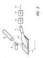
- FIG. 1 A simplified block diagram of a system in which the method of the invention can be implemented is shown in figure 1.
- a radiation image of an object was recorded on a photostimulable phosphor screen (3) by exposing (2) said screen to x-rays transmitted through the object (not shown).
- the stimulable phosphor screen was conveyed in a cassette (3) provided with an electrically erasable programmable read only memory (EEPROM).
- EEPROM electrically erasable programmable read only memory
- an identification station 4 various kinds of data, for example patient identification data (name, date of birth) and data relating to the exposure and/or to the signal processing were written into the EEPROM.
- a radiation image read-out apparatus 1 the information stored in the EEPROM and the image stored in the photostimulable phosphor screen were read-out.
- the stored image was read-out by scanning the phosphor screen with stimulating rays emitted by a laser 8.
- the stimulating rays were deflected into the main scanning direction by means of galvanometric deflection 9.
- the subscanning was performed by transporting the phosphor screen in the subscanning direction 10.
- the stimulated emission was directed by means of a light collector 12 onto a photomultiplier 11 for conversion into an electrical image representation.
- the signal was sampled by a sample and hold circuit 13, and converted into a 12 bit signal by means of an analog to digital convertor 14.
- the digital image signal 15 was sent to the image processing module of the read-out apparatus (figure 1, numeral 7) where it was stored in an internal buffer.
- the digital image signal was subjected to a decomposition into detail images at multiple resolution levels and a residual image and was then also sent from the image processor to a preview monotor 5 which gives a first impression of of the acquired image and hence will provide for early feedback to the operator in case the acquisition went wrong.
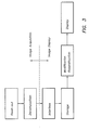
- the decomposed digital image signal was also sent via a buffer 24 to the image workstation 25,26 (25 indicating the review console and 26 indicating the review terminal) where it was temporarily stored on hard disc (cfr. fig. 3).
- Figure 3 illustrates a workstation interfaced with a read-out apparatus.
- the detail images at multiple resolution levels stored on the hard disc are retrieved (retrieval control means not shown) up to a maximum resolution level so that, when the retrieved detail images are modified and subjected to a reconstruction procedure, a reconstructed image results that has a resolution that is below the resolution of the display screen of the workstation.
- the workstation additionally comprises means for composing an image comprising more than one reconstructed image.
- detail images are retrieved up to a specific resolution level so that the resolution of the composed image is equal to or smaller than the of the display device.
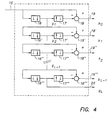
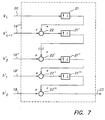
- FIG. 4 One embodiment of a decomposition process is illustrated in figure 4.
- the original image 15 is filtered by means of a low pass filter 16, and subsampled by a factor of two, which is implemented by computing the resulting low pass image g 1 only at every other pixel position of every alternate row.
- a detail image b 0 at the finest level is obtained by interpolating the low pass image g 1 while at the same time inserting an extra column and row every other column and row respectively, and pixelwise subtracting the interpolated image from the original image 15.
- the interpolation is effectuated by the interpolator 17, which inserts a column of zero values every other column, and a row of zero values every other row respectively, and next convolves the extended image with a low pass filter.
- the subtraction is done by the adder 18.
- the finest detail image b 0 has the same size as the original image.
- the next coarser detail image b 1 has only half as many rows and columns as the first detail image b 0 .
- the characteristic spatial frequency of the resulting detail image is only half of that of the previous finer detail image, and also the number of columns and rows is halved, in accordance with the Nyquist criterion.
- a residual image g L 20 is left which can be considered to be a very low resolution approximation of the original image. In the extreme case it consists of only 1 pixel which represents the average value of the original image 15.
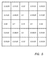
- the filter coefficients of the low pass filter of the preferred embodiment are presented in Fig. 5. They correspond approximately to the samples of a two dimensional gaussian distribution on a 5x5 grid. The same filter coefficients are used for the low pass filters 16, 16',.. 16''' at all scales. The same filter kernel with all coefficients multiplied by 4 is also used within the interpolators 17, 17',... 17'''. The factor of 4 compensates for the insertion of zero pixel columns and rows.
- the residual image 20 is first interpolated by interpolator 21 to twice its original size and the interpolated image is next pixelwise added to the detail image 19''' of the coarsest level b' L-1 , using adder 22.
- the resulting image is interpolated and added to the next finer detail image.
- this process is iterated L times using the unmodified detail images b L-1 .. b 0 then the original image 15 will result.
- the detail images are modified before reconstruction according to the findings of the present invention, then a contrast enhanced image 23 will result.
- the interpolators 21, 21' .. 21'' are identical to those used in the decomposition section.
- detail images b i were retrieved up to a resolution level so that the resolution of the reconstructed image is smaller than or equal to that of the display screen.
- the workstation was equiped with a graphic user interface wherein pre-programmed processing procedures can be specified, selected and initiated by using icons, menu's, lists etc..
- This graphic user interface for exmaple provides selection of a number of display functionalities such as display of one image (as described higher), display of two (or more) images for comparison or display of an image directory, etc.
- a composed image was built from more than one reconstructed image. Retrieval of detail images for each of the components of the composed image was then limited to a resolution level so that the image composed of the reconstructed images could be displayed given the limited resolution of the display screen.
Claims (8)
- Procédé d'affichage sur un dispositif d'affichage d'une image radiographique représentée sous la forme d'un signal numérique, comprenant les étapes consistant àcaractérisé en ce quedécomposer la représentation d'image en une séquence d'images de détail à des niveaux de résolution multiples et en une image résiduelle,stocker lesdites images de détail et ladite image résiduelle dans un dispositif de mémoire,calculer une image traitée en appliquant un algorithme de reconstitution sur l'image résiduelle et les images de détail, l'algorithme de reconstitution étant tel que, si on l'appliquait à l'image résiduelle et à toutes les images de détail sans modification, on obtiendrait ladite image d'origine ou une proche approximation de celle-ci, l'extraction d'images de détail étant par ailleurs limitée aux images de détail jusqu'à un niveau de résolution spécifique inférieur à la résolution de ladite image radiographique de façon à ce que l'image traitée, suite à cette reconstitution, présente une résolution inférieure ou égale à la résolution dudit dispositif d'affichage,afficher ladite image reconstituée,des valeurs de pixels d'images de détail extraites sont modifiées pour produire des valeurs de pixels d'un groupe d'images de détail modifiées en appliquant aux valeurs de pixels des images de détail extraites une fonction de mise en correspondance non linéaire impaire à croissance monotone, dont la pente diminue progressivement avec des valeurs d'arguments croissantes.
- Procédé d'affichage sur un dispositif d'affichage d'un certain nombre d'images radiographiques en appliquant le procédé selon la revendication 1 auxdites images et en limitant l'extraction d'images de détail, pour chacune desdites images, à un certain niveau de résolution de sorte que l'image composée obtenue suite à la reconstitution et à la composition présente une résolution inférieure ou égale à la résolution dudit dispositif d'affichage.
- Procédé selon la revendication 1 ou 2, dans lequel l'image décomposée présente une structure pyramidale, de sorte que le niveau de résolution des images de détail diffère d'un facteur de 2, et les images de détail à chaque niveau de résolution sont calculées en filtrant l'image d'origine avec la différence de deux filtres passe-bas et en sous-échantillonnant l'image résultante d'un facteur 2.
- Procédé selon la revendication 1 ou 2, dans lequel ladite image radiographique est stockée dans un écran de luminophore photostimulable et dans lequel ladite représentation d'image numérique est obtenue par balayage dudit écran à l'aide d'un rayonnement stimulant, détection de la lumière émise lors de la stimulation et conversion de ladite lumière détectée en une représentation de signal numérique.
- Appareil d'affichage d'images radiologiques comprenantun moyen pour interfacer ledit appareil d'affichage (26) avec un appareil (1) pour acquérir une représentation de signal numérique d'une image radiographique, ledit appareil d'acquisition étant pourvu d'un premier moyen de traitement (7, 16, 16', ... - 18, 18', ...) pour décomposer ladite représentation de signal numérique en images de détail à des niveaux de résolution multiples et en une image résiduelle,un moyen d'affichage,un moyen pour stocker lesdites images de détail et ladite image résiduelle,un moyen pour commander l'extraction d'images stockées,un moyen pour modifier des valeurs de pixels d'images de détail extraites pour produire des valeurs de pixels d'un groupe d'images de détail modifiées en appliquant aux valeurs de pixels des images de détail extraites une fonction de mise en correspondance non linéaire impaire à croissance monotone, dont la pente diminue progressivement avec des valeurs d'arguments croissantes,un moyen (21, 21', ... - 22, 22', ...) pour calculer, pour chaque image, une image traitée (23) en appliquant un algorithme de reconstitution sur l'image résiduelle extraite et les images de détail extraites et modifiées, l'algorithme de reconstitution étant tel que, si on l'appliquait à l'image résiduelle et à toutes les images de détail sans modification, on obtiendrait ladite image d'origine ou une proche approximation de celle-ci, ledit moyen de commande commandant par ailleurs l'extraction d'images de détail à des niveaux de résolution multiples à hauteur d'une résolution spécifique inférieure à la résolution de ladite image radiographique de façon à ce que la résolution de l'image reconstituée soit inférieure à la résolution dudit moyen d'affichage,un moyen pour commander l'affichage de ladite image reconstituée.
- Appareil selon la revendication 5, modifié en ce qu'un moyen est prévu pour composer à l'aide d'un certain nombre d'images reconstituées une image composée, et en ce que ledit moyen de commande commande l'extraction d'images de détail à des niveaux de résolution multiples à hauteur d'un niveau de résolution spécifique de façon à ce que la résolution de l'image composée soit inférieure à la résolution du moyen d'affichage.
- Appareil selon la revendication 5, comprenant une interface-utilisateur graphique permettant la sélection d'une image et d'un certain nombre de fonctionnalités d'affichage et la spécification d'une (de) procédure(s) de traitement préprogrammée(s).
- Appareil selon la revendication 5, dans lequel ladite image radiographique a été stockée dans un écran de luminophore photostimulable et dans lequel ledit appareil pour acquérir une représentation de signal numérique d'une image radiographique comprend un moyen pour balayer un écran de luminophore photostimulable à l'aide d'un rayonnement stimulant, un moyen pour détecter la lumière émise lors de la stimulation et un moyen pour convertir la lumière détectée en une représentation de signal.
Priority Applications (4)
| Application Number | Priority Date | Filing Date | Title |
|---|---|---|---|
| DE69331220T DE69331220T2 (de) | 1993-02-11 | 1993-02-11 | Verfahren zur Darstellung von Strahlungsbildern |
| EP93200373A EP0610602B2 (fr) | 1993-02-11 | 1993-02-11 | Procédé de visualisation d'images radiographiques |
| JP04034294A JP3240235B2 (ja) | 1993-02-11 | 1994-02-14 | 放射線画像の表示方法 |
| US08/571,742 US5757952A (en) | 1993-02-11 | 1995-12-13 | Method of displaying (a) radiographic image (s) |
Applications Claiming Priority (1)
| Application Number | Priority Date | Filing Date | Title |
|---|---|---|---|
| EP93200373A EP0610602B2 (fr) | 1993-02-11 | 1993-02-11 | Procédé de visualisation d'images radiographiques |
Publications (3)
| Publication Number | Publication Date |
|---|---|
| EP0610602A1 EP0610602A1 (fr) | 1994-08-17 |
| EP0610602B1 true EP0610602B1 (fr) | 2001-11-28 |
| EP0610602B2 EP0610602B2 (fr) | 2010-11-24 |
Family
ID=8213627
Family Applications (1)
| Application Number | Title | Priority Date | Filing Date |
|---|---|---|---|
| EP93200373A Expired - Lifetime EP0610602B2 (fr) | 1993-02-11 | 1993-02-11 | Procédé de visualisation d'images radiographiques |
Country Status (4)
| Country | Link |
|---|---|
| US (1) | US5757952A (fr) |
| EP (1) | EP0610602B2 (fr) |
| JP (1) | JP3240235B2 (fr) |
| DE (1) | DE69331220T2 (fr) |
Families Citing this family (13)
| Publication number | Priority date | Publication date | Assignee | Title |
|---|---|---|---|---|
| EP0610606A1 (fr) * | 1993-02-11 | 1994-08-17 | Agfa-Gevaert N.V. | Procédé pour afficher une partie d'une image |
| KR100197583B1 (ko) * | 1997-02-04 | 1999-06-15 | 이민화 | 환자용모니터를 구비한 초음파진단장치 |
| FR2764411B1 (fr) * | 1997-06-09 | 1999-07-16 | Eastman Kodak Co | Procede d'optimisation du remplissage d'un support d'edition avec des images numeriques de tailles variables, et avec conservation des rapports de tailles |
| JP4653270B2 (ja) * | 1999-08-25 | 2011-03-16 | 東芝医用システムエンジニアリング株式会社 | 磁気共鳴イメージング装置 |
| JP2001157675A (ja) * | 1999-12-02 | 2001-06-12 | Fuji Photo Film Co Ltd | 画像表示方法および画像表示装置 |
| US11204729B2 (en) | 2000-11-01 | 2021-12-21 | Flexiworld Technologies, Inc. | Internet based digital content services for pervasively providing protected digital content to smart devices based on having subscribed to the digital content service |
| US10860290B2 (en) | 2000-11-01 | 2020-12-08 | Flexiworld Technologies, Inc. | Mobile information apparatuses that include a digital camera, a touch sensitive screen interface, support for voice activated commands, and a wireless communication chip or chipset supporting IEEE 802.11 |
| US10915296B2 (en) | 2000-11-01 | 2021-02-09 | Flexiworld Technologies, Inc. | Information apparatus that includes a touch sensitive screen interface for managing or replying to e-mails |
| CN100334577C (zh) | 2000-11-01 | 2007-08-29 | 福来西奥德技术公司 | 用于设备到设备的普适数字输出的控制器及管理器 |
| US20020078101A1 (en) * | 2000-11-20 | 2002-06-20 | Chang William Ho | Mobile and pervasive output client device |
| US20020097418A1 (en) | 2001-01-19 | 2002-07-25 | Chang William Ho | Raster image processor and processing method for universal data output |
| DE60202588T2 (de) * | 2002-02-22 | 2006-01-05 | Agfa-Gevaert N.V. | Verfahren zur Rauschminderung |
| JP7098341B2 (ja) * | 2018-01-30 | 2022-07-11 | キヤノン株式会社 | 制御装置、放射線撮影システム、制御方法及びプログラム |
Family Cites Families (15)
| Publication number | Priority date | Publication date | Assignee | Title |
|---|---|---|---|---|
| US4315318A (en) * | 1978-12-26 | 1982-02-09 | Fuji Photo Film Co., Ltd. | Method and apparatus for processing a radiation image |
| JPS56104645A (en) † | 1979-12-25 | 1981-08-20 | Fuji Photo Film Co Ltd | Radiation picture treating method and its device |
| US4802019A (en) * | 1982-01-11 | 1989-01-31 | Zenji Harada | Picture processing system for selective display |
| US4674125A (en) † | 1983-06-27 | 1987-06-16 | Rca Corporation | Real-time hierarchal pyramid signal processing apparatus |
| JPS60148279A (ja) * | 1983-12-28 | 1985-08-05 | インタ−ナショナル ビジネス マシ−ンズ コ−ポレ−ション | 画像処理システム |
| US4870497A (en) * | 1988-01-22 | 1989-09-26 | American Telephone And Telegraph Company | Progressive transmission of high resolution two-tone facsimile images |
| US4933775A (en) * | 1988-03-31 | 1990-06-12 | Fuji Photo Film Co., Ltd. | Image enlarging or contracting method |
| FR2643531B1 (fr) * | 1989-02-21 | 1996-04-26 | Thomson Csf | Procede et dispositif de compression de l'information destine au decodage compatible d'une famille de signaux de television de resolutions croissantes |
| US5048111A (en) * | 1989-11-06 | 1991-09-10 | Eastman Kodak Company | Hybrid subband-based hierarchical storage and display method for high resolution digital images in a multiuse environment |
| US4969204A (en) * | 1989-11-29 | 1990-11-06 | Eastman Kodak Company | Hybrid residual-based hierarchical storage and display method for high resolution digital images in a multiuse environment |
| JP2663189B2 (ja) * | 1990-01-29 | 1997-10-15 | 富士写真フイルム株式会社 | 画像のダイナミックレンジ圧縮処理方法 |
| US5235420A (en) * | 1991-03-22 | 1993-08-10 | Bell Communications Research, Inc. | Multilayer universal video coder |
| US5297219A (en) * | 1991-06-27 | 1994-03-22 | Eastman Kodak Company | Transforms for digital images in a hierarchical environment |
| DE69214229T2 (de) * | 1991-08-14 | 1997-04-30 | Agfa Gevaert Nv | Verfahren und Vorrichtung zur Kontrastverbesserung von Bildern |
| US5325449A (en) * | 1992-05-15 | 1994-06-28 | David Sarnoff Research Center, Inc. | Method for fusing images and apparatus therefor |
-
1993
- 1993-02-11 EP EP93200373A patent/EP0610602B2/fr not_active Expired - Lifetime
- 1993-02-11 DE DE69331220T patent/DE69331220T2/de not_active Expired - Lifetime
-
1994
- 1994-02-14 JP JP04034294A patent/JP3240235B2/ja not_active Expired - Fee Related
-
1995
- 1995-12-13 US US08/571,742 patent/US5757952A/en not_active Expired - Lifetime
Also Published As
| Publication number | Publication date |
|---|---|
| EP0610602A1 (fr) | 1994-08-17 |
| US5757952A (en) | 1998-05-26 |
| JPH06325171A (ja) | 1994-11-25 |
| JP3240235B2 (ja) | 2001-12-17 |
| EP0610602B2 (fr) | 2010-11-24 |
| DE69331220T2 (de) | 2002-06-27 |
| DE69331220D1 (de) | 2002-01-10 |
Similar Documents
| Publication | Publication Date | Title |
|---|---|---|
| EP0527525B1 (fr) | Procédé et dispositif d'amélioration du contraste d'une image | |
| JP3683914B2 (ja) | ピラミッド的画像分解に基づいた放射線画像の多重処理法 | |
| US5467404A (en) | Method and apparatus for contrast enhancement | |
| US5717791A (en) | Image contrast enhancing method | |
| EP0610603B1 (fr) | Méthode interactive rapide de traitement en différé d'images radiographiques | |
| EP0610602B1 (fr) | Procédé de visualisation d'images radiographiques | |
| US6356652B1 (en) | Visualization of diagnostically irrelevant zones in a radiographic image | |
| US6480619B1 (en) | Method of displaying part of a radiographic image | |
| JPH10268451A (ja) | 細長対象物の放射画像の記録及び読取方法 | |
| US5616930A (en) | Radiation image displaying method and apparatus | |
| US6041135A (en) | Fast interactive off-line processing method for radiographic images | |
| US6344858B1 (en) | Method of evaluating image processing performed on a radiographic image | |
| EP0567176B1 (fr) | Méthode et appareil pour affichage d'image irradiée | |
| EP0741371B1 (fr) | Méthode de reproduction d'image de rayonnement | |
| EP0567174B1 (fr) | Méthode et appareil pour affichage d'image irradiée | |
| WO1995015530A1 (fr) | Codage d'images par transformations en cosinus discretes | |
| EP0654762B1 (fr) | Visualisation de zones diagnostiquement non-pertinentes dans une image de radiographie | |
| EP4105875A1 (fr) | Procédé d'amélioration de contraste | |
| EP0767576A1 (fr) | Procédé de production de diapositives pour images radiographiques |
Legal Events
| Date | Code | Title | Description |
|---|---|---|---|
| PUAI | Public reference made under article 153(3) epc to a published international application that has entered the european phase |
Free format text: ORIGINAL CODE: 0009012 |
|
| AK | Designated contracting states |
Kind code of ref document: A1 Designated state(s): BE DE FR GB NL |
|
| 17P | Request for examination filed |
Effective date: 19950217 |
|
| 17Q | First examination report despatched |
Effective date: 20000105 |
|
| GRAG | Despatch of communication of intention to grant |
Free format text: ORIGINAL CODE: EPIDOS AGRA |
|
| GRAG | Despatch of communication of intention to grant |
Free format text: ORIGINAL CODE: EPIDOS AGRA |
|
| GRAH | Despatch of communication of intention to grant a patent |
Free format text: ORIGINAL CODE: EPIDOS IGRA |
|
| GRAH | Despatch of communication of intention to grant a patent |
Free format text: ORIGINAL CODE: EPIDOS IGRA |
|
| GRAA | (expected) grant |
Free format text: ORIGINAL CODE: 0009210 |
|
| AK | Designated contracting states |
Kind code of ref document: B1 Designated state(s): BE DE FR GB NL |
|
| PG25 | Lapsed in a contracting state [announced via postgrant information from national office to epo] |
Ref country code: NL Free format text: LAPSE BECAUSE OF FAILURE TO SUBMIT A TRANSLATION OF THE DESCRIPTION OR TO PAY THE FEE WITHIN THE PRESCRIBED TIME-LIMIT Effective date: 20011128 Ref country code: BE Free format text: LAPSE BECAUSE OF FAILURE TO SUBMIT A TRANSLATION OF THE DESCRIPTION OR TO PAY THE FEE WITHIN THE PRESCRIBED TIME-LIMIT Effective date: 20011128 |
|
| RIC1 | Information provided on ipc code assigned before grant |
Free format text: 7G 06T 5/00 A |
|
| REG | Reference to a national code |
Ref country code: GB Ref legal event code: IF02 |
|
| REF | Corresponds to: |
Ref document number: 69331220 Country of ref document: DE Date of ref document: 20020110 |
|
| NLV1 | Nl: lapsed or annulled due to failure to fulfill the requirements of art. 29p and 29m of the patents act | ||
| PLBI | Opposition filed |
Free format text: ORIGINAL CODE: 0009260 |
|
| PLBF | Reply of patent proprietor to notice(s) of opposition |
Free format text: ORIGINAL CODE: EPIDOS OBSO |
|
| 26 | Opposition filed |
Opponent name: SIEMENS AG Effective date: 20020827 |
|
| PLBF | Reply of patent proprietor to notice(s) of opposition |
Free format text: ORIGINAL CODE: EPIDOS OBSO |
|
| PLBF | Reply of patent proprietor to notice(s) of opposition |
Free format text: ORIGINAL CODE: EPIDOS OBSO |
|
| RIC2 | Information provided on ipc code assigned after grant |
Ipc: 7G 06F 15/00 A |
|
| REG | Reference to a national code |
Ref country code: GB Ref legal event code: 746 Effective date: 20040921 |
|
| REG | Reference to a national code |
Ref country code: FR Ref legal event code: D6 |
|
| REG | Reference to a national code |
Ref country code: GB Ref legal event code: 732E |
|
| REG | Reference to a national code |
Ref country code: FR Ref legal event code: TP |
|
| PLAB | Opposition data, opponent's data or that of the opponent's representative modified |
Free format text: ORIGINAL CODE: 0009299OPPO |
|
| RAP2 | Party data changed (patent owner data changed or rights of a patent transferred) |
Owner name: AGFA HEALTHCARE N.V. |
|
| PUAH | Patent maintained in amended form |
Free format text: ORIGINAL CODE: 0009272 |
|
| STAA | Information on the status of an ep patent application or granted ep patent |
Free format text: STATUS: PATENT MAINTAINED AS AMENDED |
|
| 27A | Patent maintained in amended form |
Effective date: 20101124 |
|
| AK | Designated contracting states |
Kind code of ref document: B2 Designated state(s): BE DE FR GB NL |
|
| PGFP | Annual fee paid to national office [announced via postgrant information from national office to epo] |
Ref country code: GB Payment date: 20110119 Year of fee payment: 19 |
|
| PGFP | Annual fee paid to national office [announced via postgrant information from national office to epo] |
Ref country code: FR Payment date: 20111219 Year of fee payment: 20 |
|
| PGFP | Annual fee paid to national office [announced via postgrant information from national office to epo] |
Ref country code: DE Payment date: 20111205 Year of fee payment: 20 |
|
| REG | Reference to a national code |
Ref country code: DE Ref legal event code: R071 Ref document number: 69331220 Country of ref document: DE |
|
| REG | Reference to a national code |
Ref country code: GB Ref legal event code: PE20 Expiry date: 20130210 |
|
| PG25 | Lapsed in a contracting state [announced via postgrant information from national office to epo] |
Ref country code: DE Free format text: LAPSE BECAUSE OF EXPIRATION OF PROTECTION Effective date: 20130212 Ref country code: GB Free format text: LAPSE BECAUSE OF EXPIRATION OF PROTECTION Effective date: 20130210 |