EP0610043A1 - Interféromètre ultrasonique - Google Patents
Interféromètre ultrasonique Download PDFInfo
- Publication number
- EP0610043A1 EP0610043A1 EP94300689A EP94300689A EP0610043A1 EP 0610043 A1 EP0610043 A1 EP 0610043A1 EP 94300689 A EP94300689 A EP 94300689A EP 94300689 A EP94300689 A EP 94300689A EP 0610043 A1 EP0610043 A1 EP 0610043A1
- Authority
- EP
- European Patent Office
- Prior art keywords
- ultrasonic
- interferometer
- splitting
- waveguide
- waveguides
- Prior art date
- Legal status (The legal status is an assumption and is not a legal conclusion. Google has not performed a legal analysis and makes no representation as to the accuracy of the status listed.)
- Ceased
Links
Images


Classifications
-
- G—PHYSICS
- G01—MEASURING; TESTING
- G01N—INVESTIGATING OR ANALYSING MATERIALS BY DETERMINING THEIR CHEMICAL OR PHYSICAL PROPERTIES
- G01N29/00—Investigating or analysing materials by the use of ultrasonic, sonic or infrasonic waves; Visualisation of the interior of objects by transmitting ultrasonic or sonic waves through the object
- G01N29/04—Analysing solids
- G01N29/07—Analysing solids by measuring propagation velocity or propagation time of acoustic waves
- G01N29/075—Analysing solids by measuring propagation velocity or propagation time of acoustic waves by measuring or comparing phase angle
-
- G—PHYSICS
- G01—MEASURING; TESTING
- G01B—MEASURING LENGTH, THICKNESS OR SIMILAR LINEAR DIMENSIONS; MEASURING ANGLES; MEASURING AREAS; MEASURING IRREGULARITIES OF SURFACES OR CONTOURS
- G01B17/00—Measuring arrangements characterised by the use of infrasonic, sonic or ultrasonic vibrations
- G01B17/02—Measuring arrangements characterised by the use of infrasonic, sonic or ultrasonic vibrations for measuring thickness
- G01B17/025—Measuring arrangements characterised by the use of infrasonic, sonic or ultrasonic vibrations for measuring thickness for measuring thickness of coating
-
- G—PHYSICS
- G01—MEASURING; TESTING
- G01N—INVESTIGATING OR ANALYSING MATERIALS BY DETERMINING THEIR CHEMICAL OR PHYSICAL PROPERTIES
- G01N2291/00—Indexing codes associated with group G01N29/00
- G01N2291/02—Indexing codes associated with the analysed material
- G01N2291/025—Change of phase or condition
- G01N2291/0258—Structural degradation, e.g. fatigue of composites, ageing of oils
-
- G—PHYSICS
- G01—MEASURING; TESTING
- G01N—INVESTIGATING OR ANALYSING MATERIALS BY DETERMINING THEIR CHEMICAL OR PHYSICAL PROPERTIES
- G01N2291/00—Indexing codes associated with group G01N29/00
- G01N2291/02—Indexing codes associated with the analysed material
- G01N2291/028—Material parameters
- G01N2291/02854—Length, thickness
-
- G—PHYSICS
- G01—MEASURING; TESTING
- G01N—INVESTIGATING OR ANALYSING MATERIALS BY DETERMINING THEIR CHEMICAL OR PHYSICAL PROPERTIES
- G01N2291/00—Indexing codes associated with group G01N29/00
- G01N2291/02—Indexing codes associated with the analysed material
- G01N2291/028—Material parameters
- G01N2291/02881—Temperature
-
- G—PHYSICS
- G01—MEASURING; TESTING
- G01N—INVESTIGATING OR ANALYSING MATERIALS BY DETERMINING THEIR CHEMICAL OR PHYSICAL PROPERTIES
- G01N2291/00—Indexing codes associated with group G01N29/00
- G01N2291/04—Wave modes and trajectories
- G01N2291/042—Wave modes
- G01N2291/0421—Longitudinal waves
Definitions
- This invention relates generally to non-destructive measurement of local material properties.
- the invention specifically relates to an interferometer useful in determining the thickness and other material properties of thin films.
- Ultrasound is a common means of non-destructively inspecting materials for flaws and structural integrity.
- the preferred frequency used for inspection and sizing of flaws is in the range of 1-10 MHz with 2.25-5 MHz preferred.
- Pulsed ultrasonic transducers and their electronics common to the art of nondestructive examination (NDE), are typically relatively broad-band, with bandwidth roughly 40% of the nominal operating frequency. Such transducers and electronics are, therefore, ill-suited to interferometry, which requires narrow-band, or "monochromatic", continuous wave "bursts".
- the NDE acoustical paths are not critically related to inspection accuracy, except that long paths in metal reduce signal strength due to attenuation.
- interferometry requires well-defined paths of accurate lengths. Therefore, standard methods commonly applied to NDE are not directly applicable to interferometry.
- the present invention is a method of accurately measuring the thickness of thin films of materials using interference of ultrasonic waves in the frequency range of 2-15 MHz.
- the ultrasonic interferometer in accordance with the invention produces interference "fringes" that are a function of the film thickness, which fringes are used to determine the thickness.
- the film may consist of any solid material, metallic or non-metallic, having known sonic properties and a thickness on the order of the sonic wavelength.
- the choice of frequency is specific to the expected range of film thickness, and there is an inherent minimum thickness that can be measured at any given frequency of ultrasound employed.
- the interference effects are also a measure of thin-film material properties other than thickness, e.g., sonic velocity, acoustical impedance, density, elastic modulus, grain size and attenuation coefficient, which can be deduced accurately and repeatably from prepared samples. This allows the material to be characterized locally. Material structure, such as grain size and bonding integrity, can be inferred from data acquired by the interferometer.
- the invention employs ultrasonic waveguides in specific geometric relationships to define and control the acoustical path of the interfering waves, thereby creating an instrument with quantitative accuracy and high resolution.
- the invention further employs an extended, narrow-band ultrasonic source, excited by tone-burst electrical circuitry, to produce a wave packet of nearly monochromatic energy that is capable of producing measurable interference effects when directed along a well-defined and controlled acoustical path.
- the effectiveness and utility of the device is enhanced by using the narrow-band source of ultrasound in combination with guided-wave propagation to accurately define the acoustical path of the ultrasonic waves producing the interference. This provides greater measurement accuracy than has been possible in the past using broad-band, pulsed devices.
- the interferometer of the invention utilizes multi-path and multi-reflection principles to produce an acoustic intensity signal whose properties can be unambiguously interpreted with respect to material property measurements.
- Thin disks of properly selected materials e.g., LUCITE
- LUCITE properly selected materials
- phase angles ⁇ 1 and ⁇ 2 are related to the lengths of their respective propagation (acoustical) paths.
- the respective amplitudes ⁇ 1 and ⁇ 2 are determined by the refractive media in each path. In the case of optical interferometers, these amplitudes are very nearly equal; this is not the case for the ultrasonic interferometer.
- the wave intensity I is proportional to y 2, so from Eq. (3):
- the thickness of the film is ⁇ x and the phase velocity of ultrasound in the film material is v p .
- Measurement of the ultrasonic intensity at the output of the interferometer allows a determination of either ⁇ x or v p , but not both, by virtue of the cosine term in Eq. (5).
- the phase velocity in the material can be measured. Since this is a function of the material properties, such as bulk modulus, the interferometer provides the means of deducing this material property very accurately and locally in a film sample. Furthermore, ⁇ 2 is a function of attenuation (which varies with frequency) in the sample, as well as known refractive and mode-conversion ratios. It is possible, in principle, to also deduce the attenuation coefficient as a function of frequency using the instrument, although thicker films are required and less accuracy is possible than for purely thickness measurements. These are but a few examples of many potential applications of the device described below.
- the ultrasonic interferometer in accordance with the preferred embodiment of the invention is driven by a narrow-band source 8 and has acoustical paths defined by ultrasonic waveguides 14a-14d.
- the waveguides comprise tubes filled with a viscous, compressible fluid 4, e.g., water, designed for a specific frequency of wave propagation. Since thermal expansion effects can change the acoustical path lengths, the instrument includes a casing 2 which is also filled with fluid 4. The casing is filled via a fill port 6. Fluid 4 is held at constant temperature by conventional temperature control means (not shown).
- the narrow-band source 8 driven by "tone-burst” electronics (not shown), produces a wave packet of predetermined length and narrow bandwidth which propagates through couplant 10.
- the lens system 12 focuses the incident wave packet at the center-line of waveguide 14a.
- the incident wave packet propagates in waveguide 14a to a splitter 16, where it is first refracted at the front interface and then partially reflected and partially transmitted at the rear interface.
- the partially reflected portion forms a reference wave which propagates in waveguide 14c to a movable reflector 18.
- Reflector 18 reflects the reference wave back to splitter 16, with some of the reference wave being transmitted by splitter 16 toward the ultrasonic detector 20.
- Reflector 18 is mounted on a carriage 22 that slides along track 24. Carriage 22 displaces in response to rotation of a positioning screw 28 driven by an electronic drive unit 26.
- the interferometer also comprises conventional means (not shown) for accurately locating the reflector and reading out its relative position electronically.
- the portion of the incident wave that is transmitted through splitter 16 is guided by waveguide 14b to a compensator 30.
- Both the splitter and compensator are plastic plates.
- the purpose of compensator 30 is to render the acoustical path in plastic of the two ultrasonic waves equal.
- Compensator 30 also corrects for the fact that the source is not perfectly monochromatic. This is accomplished by placing compensator 30 at a distance from splitter 16 which is selected to produce a standing wave of the desired frequency in the waveguide cavity therebetween.
- the compensator and splitter cooperate to act as a very selective frequency filter akin to an optical interference filter.
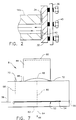
- the filtered ultrasonic wave then propagates to a substrate 32 with a thin film sample 34 deposited on its front surface.
- the substrate 32 has a very narrow gas gap 42 (see FIG. 2) machined therein specifically to form a very efficient reflector of ultrasound.
- the wave impinging on the thin film is partially reflected at the film surface.
- the remainder of the wave propagates through the film and is totally reflected at the film/gas gap interface.
- the reflected portions ("echoes") are ultimately partially reflected by splitter 16 and guided to detector 20 by waveguide 14d.
- the first and second echoes returned to splitter 16 by the thin film have phases which are functions of the position of the film surface and the film thickness.
- the instrument is carefully calibrated using the leveling screws 40 and slide positioning screw 28 to provide destructive interference at the detector due to waveguide acoustical paths.
- Detector 20 may be either an amplitude detector or an intensity detector of conventional design.
- the length of the interferometer leg formed by waveguide 14c is adjusted by incremental movement of carriage 22.
- the instrument can be calibrated by installing a calibration reflector (not shown) in place of the thin film sample and then determining which setting of carriage 22 and orientation of the calibration reflector produce a null at detector 20.
- the orientation of the calibration reflector (and the thin-film sample) can be adjusted using leveling screws 40.
- the thin film sample is substituted for the calibration reflector, its position being adjusted such that an ultrasonic wave reflected from the surface of the thin film to detector 20 is 180° out of phase with the wave reflected from reflector 18.
- the calibration reflector and thin-film sample can be interchanged by removing cap 38 or by installing a rotating head having the calibration reflector and thin-film sample mounted thereon at respective angular positions.
- the only wave detected at detector 20 is due to film penetration by the wave and subsequent reflection at the film/gas gap interface, resulting in the wave phase change of interest.
- the film thickness can be determined from this phase change coupled with the time-of-flight of the ultrasonic wave reflected at the film surface.
- the position of reflector 18 at which the desired interference pattern between its echo and the first echo of the thin film is produced effectively establishes the transit time of the latter.
- the position of reflector 18 will then be precisely adjusted until the desired interference pattern is produced between the echo from reflector 18 and the second echo from the thin film.
- Thin film thickness is determined by counting the number of fringes in the monochromatic ultrasonic wave which cross the center of the field of view of the detector 20 during adjustment of reflector 18.
- the positions of mirror 18 and the surface of thin film 34 can be adjusted to produce constructive interference, i.e., the ultrasonic wave received at detector 20 is substantially the same as that inputted by the source, disregarding losses along the respective acoustical paths.
- the peak-to-peak attenuation is a result of attenuation of the ultrasonic wave as it traverses the film thickness.
- the attenuation increases with frequency and essentially damps out the higher-order interference effects.
- the monochromatic ultrasonic transducer 8 shown in detail in FIG. 7, comprises a piezoelectric crystal 44 mounted on a face 72 of a block 46 (hereinafter "shoe") made of a material having an index of refraction substantially equal to that of the couplant 10. Face 72 is parallel to outer shoe surface 62 and gap 52.
- the preferred material is an acrylic resin such as LUCITE.
- a convergent lens 48 is arranged between piezoelectric crystal 44 and shoe 46.
- the piezoelectric crystal 44 is excited to oscillate by an electrical driving signal imposed at fluid 54, the partial transmission at one interface of gap 52 constructively interferes with the partial reflection at the opposite interface of the gap, creating a standing wave in the fluid-filled gap.
- This effect occurs when the gap width is a half-integral number of wavelengths.
- the dimensional width of gap 52 is critical.
- the gap width is in the range of 0.002 to 0.012 inch, depending on the frequency to be selected.
- the fluid-filled gap acts as a very selective frequency filter, akin to an optical interference filter.
- the ultrasonic waveguides 14a-14d each comprise a flexible tube filled with viscous, compressible fluid.
- the ultrasonic compressional waves from narrow-band source 8 propagate axially in the fluid.
- the tube has a wall with an inner surface which is axisymmetric and of constant cross section.
- the tube may be made of metal, plastic or metal/plastic composite material.
- Such an ultrasonic waveguide is disclosed in European Patent Application Serial No. 93308306.5.
- the "legs" of the interferometer are shown in FIG. 1 as being conventional crystal driving means 60 at its design frequency by external drive electronics (not shown).
- the piezoelectric crystal produces a compressional wave (L-wave) beam.
- This beam is focused by convergent lens 48 to form a convergent ray bundle 50 propagating in shoe 46.
- Shoe 46 is machined to form a very narrow disk-shaped gap 52 of uniform height therein. Although not required, it is desirable that gap 52 be parallel to outer shoe surface 62 to eliminate refraction effects.
- the disk-shaped cell is out-gassed and back-filled, via a small port 68 and a pinch-off tube 70, with a pure fluid 54.
- the preferred fluid is water.
- the fluid 54 in gap 52 is maintained at a constant temperature by a heater rod 56.
- the heat output of heater rod 56 is monitored by a thermocouple 58.
- a controller (not shown) is used to regulate the electric current supplied to the heater element in dependence on the signal received by the thermocouple.
- the controller is programmed in a conventional manner to maintain the fluid at a constant elevated temperature.
- the sonic velocity and the gap width are selected such that a single-mode standing wave is excited resonantly in the gap 52 at the desired frequency, allowing an ultrasonic beam 64 to penetrate the gap unperturbed to impinge upon the outer shoe surface 62.
- the ultrasonic beam 64 is transmitted at outer shoe surface 62 to propagate in the direction of ray 66.
- the transmitted beam contains highly monochromatic energy due to the frequency selectivity of the gap.
- the convergent ray bundle 50 incident on the gap 52 will be partially transmitted and partially reflected at the interfaces.
- This partial transmission and partial reflection will vary with the dimension of the gap 52, the type of fluid therein and the frequency of the sound. For the proper frequency of sound within perpendicular, but this is a special case. They can be at any convenient angle, set by design. All such variations and modifications are intended to be encompassed by the claims set forth hereinafter.
Applications Claiming Priority (2)
| Application Number | Priority Date | Filing Date | Title |
|---|---|---|---|
| US11560 | 1993-02-01 | ||
| US08/011,560 US5373742A (en) | 1993-02-01 | 1993-02-01 | Ultrasonic interferometer |
Publications (1)
| Publication Number | Publication Date |
|---|---|
| EP0610043A1 true EP0610043A1 (fr) | 1994-08-10 |
Family
ID=21750932
Family Applications (1)
| Application Number | Title | Priority Date | Filing Date |
|---|---|---|---|
| EP94300689A Ceased EP0610043A1 (fr) | 1993-02-01 | 1994-01-31 | Interféromètre ultrasonique |
Country Status (4)
| Country | Link |
|---|---|
| US (1) | US5373742A (fr) |
| EP (1) | EP0610043A1 (fr) |
| JP (1) | JPH074945A (fr) |
| TW (1) | TW238353B (fr) |
Cited By (1)
| Publication number | Priority date | Publication date | Assignee | Title |
|---|---|---|---|---|
| NL1019020C2 (nl) * | 2001-09-24 | 2003-03-25 | Tno | Endfire-bundelpatroonverwerking voor akoestische interferometer. |
Families Citing this family (3)
| Publication number | Priority date | Publication date | Assignee | Title |
|---|---|---|---|---|
| US20040065188A1 (en) * | 2001-01-12 | 2004-04-08 | Stuebner Fred E. | Self-aligning ultrasonic sensor system, apparatus and method for detecting surface vibrations |
| JP4392497B2 (ja) * | 2004-07-16 | 2010-01-06 | 国立大学法人埼玉大学 | 超音波干渉縞を用いた形状解析方法 |
| WO2016115270A1 (fr) * | 2015-01-14 | 2016-07-21 | Qi2 Elements, Llc | Sélection de paramètre de fonctionnement de transducteur automatique |
Citations (4)
| Publication number | Priority date | Publication date | Assignee | Title |
|---|---|---|---|---|
| DE2709686A1 (de) * | 1977-03-05 | 1978-09-07 | Krautkraemer Gmbh | Optisches interferometrisches verfahren zur messung der oberflaechenauslenkung eines pruefstueckes unter ultraschalleinfluss |
| GB2147102A (en) * | 1983-09-23 | 1985-05-01 | Texaco Development Corp | Acoustic pulse-echo wall thickness method and apparatus |
| EP0236175A1 (fr) * | 1986-02-03 | 1987-09-09 | Mtm Leader Sarl | Mesureur d'épaisseurs de revêtements par interférométrie ultrasonore |
| EP0428443A1 (fr) * | 1989-11-14 | 1991-05-22 | AEROSPATIALE Société Nationale Industrielle | Dispositif et sonde pour mesurer la variation de distance séparant les deux faces d'une couche de matière au moyen d'ultrasons |
Family Cites Families (2)
| Publication number | Priority date | Publication date | Assignee | Title |
|---|---|---|---|---|
| FR2183387A5 (fr) * | 1972-05-05 | 1973-12-14 | Radiologie Cie Gle | |
| US5271274A (en) * | 1991-08-14 | 1993-12-21 | The Board Of Trustees Of The Leland Stanford Junior University | Thin film process monitoring techniques using acoustic waves |
-
1993
- 1993-02-01 US US08/011,560 patent/US5373742A/en not_active Expired - Fee Related
- 1993-09-29 TW TW082108006A patent/TW238353B/zh active
-
1994
- 1994-01-31 JP JP6008935A patent/JPH074945A/ja not_active Withdrawn
- 1994-01-31 EP EP94300689A patent/EP0610043A1/fr not_active Ceased
Patent Citations (4)
| Publication number | Priority date | Publication date | Assignee | Title |
|---|---|---|---|---|
| DE2709686A1 (de) * | 1977-03-05 | 1978-09-07 | Krautkraemer Gmbh | Optisches interferometrisches verfahren zur messung der oberflaechenauslenkung eines pruefstueckes unter ultraschalleinfluss |
| GB2147102A (en) * | 1983-09-23 | 1985-05-01 | Texaco Development Corp | Acoustic pulse-echo wall thickness method and apparatus |
| EP0236175A1 (fr) * | 1986-02-03 | 1987-09-09 | Mtm Leader Sarl | Mesureur d'épaisseurs de revêtements par interférométrie ultrasonore |
| EP0428443A1 (fr) * | 1989-11-14 | 1991-05-22 | AEROSPATIALE Société Nationale Industrielle | Dispositif et sonde pour mesurer la variation de distance séparant les deux faces d'une couche de matière au moyen d'ultrasons |
Cited By (2)
| Publication number | Priority date | Publication date | Assignee | Title |
|---|---|---|---|---|
| NL1019020C2 (nl) * | 2001-09-24 | 2003-03-25 | Tno | Endfire-bundelpatroonverwerking voor akoestische interferometer. |
| WO2003027663A1 (fr) * | 2001-09-24 | 2003-04-03 | Nederlandse Organisatie Voor Toegepast- Natuurwetenschappelijk Onderzoek Tno | Traitement d'un diagramme de faisceau a rayonnement longitudinal destine a un interferometre acoustique |
Also Published As
| Publication number | Publication date |
|---|---|
| JPH074945A (ja) | 1995-01-10 |
| US5373742A (en) | 1994-12-20 |
| TW238353B (fr) | 1995-01-11 |
Similar Documents
| Publication | Publication Date | Title |
|---|---|---|
| Hutchins et al. | A laser study of transient Lamb waves in thin materials | |
| US5979241A (en) | Delay line for an ultrasonic probe and method of using same | |
| US7124635B2 (en) | Evaluation method for coefficient of thermal expansion of ultra-low-expansion glass material | |
| Fujii et al. | Accurate measurements of the sound velocity in pure water by combining a coherent phase‐detection technique and a variable path‐length interferometer | |
| Simonetti et al. | A guided wave technique for the characterization of highly attenuative viscoelastic materials | |
| Pouet et al. | Measurement of broadband intrinsic ultrasonic attenuation and dispersion in solids with laser techniques | |
| US5492012A (en) | Time-of-flight method for sizing cracks through fluid-filled gaps in structures | |
| US5373742A (en) | Ultrasonic interferometer | |
| Deán et al. | Determination of thickness and elastic constants of aluminum plates from full-field wavelength measurements of single-mode narrowband Lamb waves | |
| Tietze et al. | Visualization of the interaction of guided acoustic waves with water by light refractive vibrometry | |
| US4492117A (en) | Ultrasonic nondestructive test apparatus | |
| Bayón et al. | Estimation of dynamic elastic constants from the amplitude and velocity of Rayleigh waves | |
| Buick et al. | Application of the acousto-optic effect to pressure measurements in ultrasound fields in water using a laser vibrometer | |
| Papadakis | The measurement of small changes in ultrasonic velocity and attenuation | |
| RU2353925C1 (ru) | Устройство для бесконтактного высокоточного измерения физико-технических параметров объекта | |
| Simonetti et al. | Ultrasonic interferometry for the measurement of shear velocity and attenuation in viscoelastic solids | |
| Costley et al. | Viscosity measurement with laser-generated and detected shear waves | |
| Tsukahara et al. | An acoustic micrometer and its application to layer thickness measurements | |
| JP2973759B2 (ja) | 結晶粒度の測定装置 | |
| Bifulco et al. | Ultrasonic pulse spectroscopy of a solid inclusion in an elastic solid | |
| RU2786510C1 (ru) | Способ измерения скорости звука в тонких полимерных звукопрозрачных пленках | |
| Varadé et al. | Experimental results on bulk waves and Rayleigh waves in slate | |
| JPH03205557A (ja) | 超音波顕微鏡の探触子 | |
| RU2067760C1 (ru) | Акустооптический способ контроля качества объектов и устройство для его осуществления | |
| JPH0251012A (ja) | 超音波を用いた肉厚測定方法、及び同装置 |
Legal Events
| Date | Code | Title | Description |
|---|---|---|---|
| PUAI | Public reference made under article 153(3) epc to a published international application that has entered the european phase |
Free format text: ORIGINAL CODE: 0009012 |
|
| AK | Designated contracting states |
Kind code of ref document: A1 Designated state(s): CH DE ES LI |
|
| 17P | Request for examination filed |
Effective date: 19950210 |
|
| GRAG | Despatch of communication of intention to grant |
Free format text: ORIGINAL CODE: EPIDOS AGRA |
|
| 17Q | First examination report despatched |
Effective date: 19961218 |
|
| STAA | Information on the status of an ep patent application or granted ep patent |
Free format text: STATUS: THE APPLICATION HAS BEEN REFUSED |
|
| 18R | Application refused |
Effective date: 19970606 |