EP0610001B1 - Loudspeaker - Google Patents
Loudspeaker Download PDFInfo
- Publication number
- EP0610001B1 EP0610001B1 EP19940300426 EP94300426A EP0610001B1 EP 0610001 B1 EP0610001 B1 EP 0610001B1 EP 19940300426 EP19940300426 EP 19940300426 EP 94300426 A EP94300426 A EP 94300426A EP 0610001 B1 EP0610001 B1 EP 0610001B1
- Authority
- EP
- European Patent Office
- Prior art keywords
- diaphragm
- loudspeaker
- bobbin
- voice coil
- cellulose
- Prior art date
- Legal status (The legal status is an assumption and is not a legal conclusion. Google has not performed a legal analysis and makes no representation as to the accuracy of the status listed.)
- Expired - Lifetime
Links
Images


Classifications
-
- H—ELECTRICITY
- H04—ELECTRIC COMMUNICATION TECHNIQUE
- H04R—LOUDSPEAKERS, MICROPHONES, GRAMOPHONE PICK-UPS OR LIKE ACOUSTIC ELECTROMECHANICAL TRANSDUCERS; DEAF-AID SETS; PUBLIC ADDRESS SYSTEMS
- H04R9/00—Transducers of moving-coil, moving-strip, or moving-wire type
- H04R9/02—Details
- H04R9/04—Construction, mounting, or centering of coil
-
- H—ELECTRICITY
- H04—ELECTRIC COMMUNICATION TECHNIQUE
- H04R—LOUDSPEAKERS, MICROPHONES, GRAMOPHONE PICK-UPS OR LIKE ACOUSTIC ELECTROMECHANICAL TRANSDUCERS; DEAF-AID SETS; PUBLIC ADDRESS SYSTEMS
- H04R7/00—Diaphragms for electromechanical transducers; Cones
- H04R7/02—Diaphragms for electromechanical transducers; Cones characterised by the construction
- H04R7/12—Non-planar diaphragms or cones
- H04R7/122—Non-planar diaphragms or cones comprising a plurality of sections or layers
- H04R7/125—Non-planar diaphragms or cones comprising a plurality of sections or layers comprising a plurality of superposed layers in contact
Definitions
- the present invention relates to a loudspeaker. More particularly, the present invention relates to a loudspeaker having a diaphragm and a bobbin carrying a voice coil wound thereon.
- a loudspeaker comprising: a diaphragm; a bobbin connected to said diaphragm; a voice coil wound on said bobbin; and a magnetic circuit arranged facing said voice coil.
- the driving coil is magnetically connected to a magnetic circuit including a magnet and magnetic components and is placed in a uniform magnetic field. Consequently, if the current according to acoustic signals, such as voice signals, is allowed to flow through the driving coil, the bobbin is set into oscillations which are transmitted to the diaphragm for outputting the reproduced sound based on the acoustic signals.
- a conical-shaped diaphragm for mid- to low-frequency sounds and a hemispherical-shaped dome diaphragm for high-frequency sound are commonly employed.
- the diaphragm for low-frequency sound is normally formed of paper, high molecular weight polymers or aluminum, while the diaphragm for high-frequency sound is normally formed of paper, films of high molecular weight polymers such as polypropyline or polyethylene terephthalate cloths, or metallic materials.
- EP-A-0,457,474 discloses manufacturing an acoustic diaphragm for a loudspeaker from cellulose produced by bacterial cultivation.
- the diaphragm is connected to a voice coil bobbin wound with the driving coil or voice coil.
- the cone-shaped diaphragm has the apex of the cone as an opening to which the bobbin is bonded with an adhesive.
- the dome-shaped diaphragm has an opening at a lower area of the hemisphere to which the bobbin is bonded with an adhesive.
- the voice coil bobbin is usually formed of paper or aluminum.
- the voice coil bobbin is driven into oscillations by changes in the acoustic current flowing through the driving coil. These oscillation are transmitted to the diaphragm.
- the bobbin material is preferably lightweight and of higher toughness.
- the voice coil bobbin is usually formed of paper or aluminum. If the bobbin is formed of paper, having the Young's modulus on the order of 1.5 to 2 (GPa) and being of low toughness, it is impossible to transmit the oscillations satisfactorily to the diaphragm. If the bobbin is formed of aluminum, the eddy current is generated in the voice coil bobbin due to electrical conductivity of the material to interfere with high fidelity reproduction.
- the metal including aluminum or the high molecular material has a higher value of Q (sharpness of resonance) such that sufficient acoustic properties cannot be realized.
- a loudspeaker comprising: a diaphragm; a bobbin connected to said diaphragm; a voice coil wound on said bobbin; and a magnetic circuit arranged facing said voice coil, characterised in that said bobbin and said diaphragm are molded as one from cellulose produced by bacterial cultivation.
- a method of manufacturing a loudspeaker bobbin and diaphragm comprising: producing cellulose by cultivating bacteria; and molding a loudspeaker bobbin and diaphragm as one from said cellulose.
- the bobbin wound by the voice coil is formed of cellulose produced by bacterial cultivation
- the bobbin is lightweight and improved in toughness, while having a lower value of Q (sharpness of resonance) and a lower electrical conductivity.
- Q sharpness of resonance
- the driving force of the diaphragm produced in the bobbin may be satisfactorily transmitted to the diaphragm, while the unusual sound proper to the bobbin material becomes less liable to be produced.
- the loudspeaker may be provided which exhibits satisfactory acoustic characteristics from the low-frequency sound range up to the high-frequency sound range and high fidelity in sound reproduction.
- Fig. 1 shows, in a schematic cross-sectional view, a loudspeaker which is not an embodiment of the present invention but is useful for understanding.
- the loudspeaker includes a conical-shaped diaphragm 1 having an opening 1a at an apex, a voice coil bobbin 3 which is a cylinder dimensioned to be fitted in the opening 1a and a voice coil 4 as a driving coil wound on the bobbin 3.
- the diaphragm 1 and the bobbin 3 are bonded to each other at 1b and 3a such as with an adhesive.
- the voice coil 4 is magnetically coupled to a magnetic circuit 2 and placed in a uniform magnetic field, so that, when the current based on acoustic signals is caused to flow in the voice coil 4, the voice coil bobbin 3 is excited into vibrations. As a result thereof, the vibrations of the bobbin 3 are transmitted to the diaphragm 1 for outputting the reproduced sound based on the acoustic signals.
- the diaphragm 1 has its other end 1c bonded at 5a to an edge member 5, and is connected via the edge member 5 to a frame 6.
- a damper 7 is mounted between the magnetic circuit 2 and an upper portion of the voice coil bobbin 3 or the bonded portion of the diaphragm 1 to the voice coil bobbin 3.
- the diaphragm 1 and the bobbin 3 are supported by the damper 7 and the edge member 5 for being oscillated in a vertical direction in Fig. 1.
- the diaphragm 1 is formed of paper, high molecular material or aluminum
- the voice coil bobbin 3 is formed of bacterial cellulose produced by culturing bacteria.
- the bacterial cellulose is formed by highly crystalline ⁇ -cellulose and, because of its extremely high surface orientation characteristics, exhibits extremely high toughness. It is also tenuous, being 0.02 to 0.04 ( ⁇ m) in thickness. While differing with the manufacture methods, the Young's modulus of the bacterial cellulose is not less than 5 to 20 (GPa). Besides, the bacterial cellulose has a sharpness of resonance Q on the same order as that of paper.
- the bacteria capable of producing the bacterial cellulose may be typified by acetic acid bacteria.
- these bacteria include Acetobacter aceti, Acetobacter xylinum, Acetobacter rancens, Sarcina ventriculi, Bacterium xyloides, Acetobacter pasteurianus, Agrobacterium tumefacien and further the genus Pseudomonas and the genus Rhizobium.
- the bacterial cellulose may be produced by a method of generating a thickened material of a certain thickness in an interface between air and the culture medium, or by aerated and agitated culturing.
- U.S. Patent No. 4, 742, 164 As for the bacterial cellulose, reference is had to U.S. Patent No. 4, 742, 164.
- the magnetic circuit 2 is made up of a yoke 2a having a center pole 2b, a permanent magnet 2c and a plate 2d, as shown in Fig. 1.
- the upper end of the center pole 2b is introduced into the opening 1a.
- an assembly of the bobbin 3 and the voice coil 4 is inserted into the gap defined between the center pole 2b and the plate 2d.
- the voice coil 4 is positioned in a DC magnetic field of the magnetic circuit 2 and the alternating current based on the acoustic signals is supplied to the coil 4 to generate a driving force whereby the bobbin 3 is moved to and from in the oscillating direction, that is towards above and below in Fig. 1, as described above.
- the frame 6 has its lower end secured to the upper surface of the plate 2d, while the damper 7 has its one end fastened to the frame 6, which in turn is secured to the plate 2d such as with an adhesive or set screws.
- the voice coil bobbin is produced from the cellulose produced by the above mentioned bacteria in the following manner.
- the cellulose as produced is processed into a liquid suspension in readiness for paper-making-like process.
- the cellulose in the state of liquid suspension is processed by a paper-making-like process into a sheet-like member.
- the sheet-like member containing the moisture, is dried and pressed with a heated press.
- the sheet-like member, thus pressed and dried, is severed to bobbin blanks each having a suitable size.
- the bobbin blanks as severed are wound on a cylindrical-shaped winding jig into a tubular form. With the bobbin blanks thus wound on the winding jig, a lead wire having an adhesive coated thereon is wound on the bobbin blanks.
- junction areas of the as-severed bobbin blanks are bonded with an adhesive or the like.
- the resulting assembly is heated and dried in this situation.
- the adhesive coated on the surface of the lead wire is cured to bond the turns of the lead wire to one another while bonding the bobbin blanks to the lead wire.
- the winding jig is extracted to complete the voice coil bobbin.
- the above constitution of the loudspeaker may be applied to a loudspeaker having a dome-shaped diaphragm as shown in Fig. 2, which is not an embodiment of the present invention but is useful for understanding.
- the loudspeaker of Fig 2 includes a semi-circular diaphragm 11, having an opening 11a, a voice coil bobbin 13 which is a cylindrical-shaped member dimensioned to be fitted into the opening 11a and a voice coil 14 as a driving coil wound on the voice coil bobbin 13.
- the diaphragm 11 is bonded to the bobbin 13 at 11b and 13a to each other such as with an adhesive.
- the operating state of the loudspeaker is the same as described in connection with the preceding first embodiment.
- the diaphragm 11 is bonded at 15a to a damper 15 on a bonding surface 11c thereof opposite to its surface having the bonded portion 11b.
- the damper 15 in turn is bonded to a stationary portion of the loudspeaker.
- the diaphragm 11 is formed of paper, a film of a high molecular material, cloth or a metal material, while the coil bobbin 13 is formed of bacterial cellulose, as in the preceding loudspeaker.
- the voice coil bobbin was formed from bacterial cellulose and its characteristics were evaluated. Thus it was found that the formed product had a Young's modulus on the order of 10 (GPa) which is about five times that of paper commonly employed as the diaphragm material. The formed product also had the acuteness of resonance Q equal to 30 which is about one-tenth of that of aluminum commonly employed for the ordinary diaphragm. Since the loudspeaker of the present embodiment is higher in toughness and lower in the acuteness of resonance Q than the loudspeaker employing a voice coil bobbin formed of usual materials, such as paper or aluminum, it exhibits satisfactory acoustic characteristics and sound reproducibility of high fidelity over a broad range of frequency from the low-frequency range up to a high-frequency range.
- the adhesive exhibits the toughness which is markedly different from that of the diaphragm or the voice coil bobbin. Since the oscillations of the voice coil bobbin are transmitted via the adhesive to the diaphragm, there is a risk that the oscillations cannot be transmitted correctly to the diaphragm, thus placing limitations in improving the fidelity in sound reproduction.
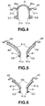
- Figs. 3 and 4 illustrate loudspeakers which are embodiments of the present invention and in which the diaphragm is formed as one with the voice coil bobbin.
- Fig. 3 shows the first embodiment in which a cone type diaphragm is employed.
- the loudspeaker of the first embodiment includes a diaphragm 21 having the shape of a cone an apex of which is opened and extended in the form of a cylinder to form a cylindrical-shaped portion 21a, and a voice coil 23 as a driving coil wound about the cylindrical portion 21a.
- the operation of the first embodiment is the same as that of the previously described loudspeakers of Figs 1 and 2, that is, the cylindrical portion 21a, corresponding to the voice coil bobbin, is oscillated by changes caused in the acoustic current flowing in the driving coil 23.
- the oscillations produced in the cylindrical-shaped portion 21a are transmitted to a cone-shaped vibrating portion 21b corresponding to the diaphragm for outputting the reproduced sound based on the acoustic signals.
- the diaphragm 21 similarly to the loudspeaker of Figs 1 and 2, the diaphragm 21 has its other end bonded to an edge member 25 at 21a and 25a such as with an adhesive.
- the diaphragm is secured to a frame, not shown, via the edge member 25.
- the diaphragm 21 of the first embodiment is formed of bacterial cellulose.
- the diaphragm and the cylindrical portion are formed as one from the bacterial cellulose, there is no portion from the diaphragm up to the cylindrical portion as the voice coil bobbin which is markedly different in toughness, so that the oscillations produced in the cylindrical portion may be transmitted more accurately to the diaphragm.
- a dome type diaphragm may also be formed in the above-described manner.
- a loudspeaker which employs such diaphragm and is the second embodiment of the present invention is shown in Fig. 4.
- the loudspeaker of the second embodiment comprises a diaphragm 31 in the form of a hemisphere an opening end of which is extended apart in the form of a cylinder to form a cylindrical portion 31a, and a voice coil 33 as a driving coil wound on the cylindrical portion 31a corresponding to the voice coil bobbin.
- the operation of the loudspeaker according to the second embodiment is the same as that of the preceding loudspeakers.
- the diaphragm 31 is bonded to a damper 35 at 31c and 35a such as with an adhesive and is secured via the damper 35 to a stationary part of the loudspeaker, not shown.
- the diaphragm 31 is formed of bacterial cellulose.
- the loudspeaker having the dome-shaped diaphragm formed as one with the diaphragm from the bacterial cellulose may be suitably employed as a speaker for reproducing the high-frequency sound.
- the loudspeaker including the diaphragm and the voice coil bobbin formed as one with each other is produced in the following manner.
- the process up to the step of forming a sheet-like member from the cellulose produced by bacteria is the same as the process for producing the voice coil bobbin as described above and hence the corresponding description is not made herein for clarity.
- the sheet-like member is placed on a carrier and the resulting sheet-like member / carrier unit is introduced into a cavity defined between convex and concave mold halves of a dome-shaped flash mold so as to be pressed by the flash mold and heated.
- the concave mold half is formed of a high water permeability material permitting high water drainage and water contents are sucked by a vacuum pump simultaneously with drainage by the press.
- the sheet-like member is molded after the shape of the mold.
- the mold cavity defined between the convex and concave mold halves is so set as to conform to the cross-sectional shape of the diaphragm integrated to the bobbin in order to permit the cone or dome-shaped diaphragm to be molded integrally with the voice coil bobbin, as shown in Figs. 3 and 4. Since the bottom portion of the voice coil bobbin of the molded mass produced by the mold halves still remains solid, this bottom portion is machined for forming an opening therein. A winding jig is then introduced via the opening in the same manner as described previously in connection with the preparation of the voice coil bobbin.
- a lead wire is placed around the portion which will prove to be the voice coil bobbin of the molded mass.
- a diaphragm-voice coil bobbin assembly including the diaphragm molded as one with the portion of the molded mass which will prove to be the voice coil bobbin as shown in Figs. 3 and 4 is produced.
- the foregoing description has been made of a one-layer diaphragm.
- the loudspeaker having a multi-layer diaphragm of increased thickness such as the loudspeaker for mid- and low-frequency sounds, according to further embodiments of the present invention, is hereinafter explained.
- loudspeakers which have cone diaphragms and are the third and fourth embodiments of the present invention, are shown in Figs. 5 and 6, respectively.
- the operation of the loudspeakers is the same as described above.
- a second diaphragm material 46 is laminated on the outer wall of a conical portion 41b of the diaphragm 41.
- a second diaphragm material 46 is laminated on the inner wall of the conical portion 41b of the diaphragm 41.
- the diaphragm 41 in each of the third and fourth embodiments is formed of bacterial cellulose.
- any of commonly employed diaphragm materials including paper, films of high molecular materials, mica or high strength fibers, such as carbon fibers or aromatic polyamides, may be employed. Of these diaphragm materials, paper exhibits satisfactory bonding properties with respect to the bacterial cellulose and hence is most preferred.
- the outer edge of the diaphragm 41 is bonded to an edge member 45 which in turn is bonded to a frame, not shown. As a result thereof, the diaphragm 41 is supported for free oscillation by a stationary portion of the loudspeaker.
- the second diaphragm material 46 of paper may be provided on the conical portion 41b of the diaphragm 41 with the aid of an adhesive, as described above.
- the second diaphragm material may also be deposited by a method similar to the paper-making method.
- the second diaphragm material 46 of paper is formed in a cone shape as shown in Figs. 5 and 6 by the process similar to the paper-making process.
- the second diaphragm material 46 thus produced is transferred into a mold of a larger depth and the diaphragm 41 of bacterial cellulose is formed on the second diaphragm material 46 by the process similar to the paper-making process.
- the conical portion 41b of the diaphragm 41 is bonded to the second diaphragm material 46 by the hydrogen bond.
- the diaphragm may be increased in thickness by providing the second material 46 on the conical portion 41b of the diaphragm 41. Since the high-frequency range of frequency characteristics of the loudspeaker is extended in proportion to the cube of the diaphragm thickness, the diaphragm of an increased thickness is required for the mid to low-frequency sound.
- the diaphragm shown in Figs. 5 or 6 not only the diaphragm 41 is increased in thickness by the provision of the second diaphragm material 46 but also the high-frequency range of the frequency characteristics may be extended further by employing bacterial cellulose as the material for diaphragm 41. Although it may be contemplated to produce a diaphragm of increased thickness using the bacterial cellulose, this method is not preferred because the paper-making-like process represents a time-consuming operation.
- the properties required of the second diaphragm material 46 include high longitudinal wave propagating velocity and a lower Q value. If paper is used as the material for the second diaphragm material 46, the characteristics of the loudspeakers for the mid to low-frequency sound may be improved as compared to the case of employing the high strength fibers of mica because the second diaphragm material 46 formed of paper may be bonded more satisfactorily to the first diaphragm material 41 by hydrogen bonds. Besides, the second diaphragm material 46 formed of paper is desirable in view of productions costs.
- Loudspeakers which have dome diaphragms and are fifth and sixth embodiments of the present invention are shown in Figs. 7 and 8, respectively.
- Each of the fifth and sixth embodiments shown in Figs. 7 and 8, respectively includes a diaphragm 51 having the shape of a hemisphere the lower portion of which is opened and extended in the form of a cylinder to form a cylindrical portion 51a and a voice coil 53 as a driving coil wound on the cylindrical portion 51a.
- the operation of the loudspeakers is the same as described above in connection with the loudspeaker of Fig. 2 and the second embodiment.
- a second diaphragm material 56 is laminated on the inner wall of a hemispherical portion 51b of the diaphragm 51.
- a second diaphragm material 56 is laminated on the outer wall of the hemispherical portion 51b of the diaphragm 51.
- the diaphragm 51 in each of the fifth and sixth embodiments is formed of bacterial cellulose. Since the dome diaphragm is suited to a loudspeaker for the high-frequency sound, the second diaphragm material 56 is preferably formed of metal materials, such as Ti or Al.
- the diaphragm 51 is bonded to an edge member 45 which in turn is bonded to a stationary portion of the loudspeaker, not shown. As a result thereof, the diaphragm 51 is supported for free oscillations by the loudspeaker.
- the high-frequency range of the frequency characteristics of the loudspeaker may be extended by virtue of the metallic material of the second diaphragm material 56. Simultaneously, the acute peak of resonance generated in the high-frequency range of the frequency characteristics due to the use of the metallic material of the second diaphragm material 56 is alleviated by the use of bacterial cellulose as the diaphragm material. If the loudspeaker shown in Figs.
- a loudspeaker having satisfactory response characteristics may be realized because the rise time responsive to input signals is faster than with the use of materials other than the bacterial cellulose on account of the reduced weight of the diaphragm 51 itself and also because attenuation of the oscillations on sound interruption is incurred more quickly on account of the lower value of Q of the bacterial cellulose constituting the diaphragm 51.
Description
- The present invention relates to a loudspeaker. More particularly, the present invention relates to a loudspeaker having a diaphragm and a bobbin carrying a voice coil wound thereon. For example, EP-A-0,256,743, on which the two part form of
claim 1 is based, discloses a loudspeaker comprising: a diaphragm; a bobbin connected to said diaphragm; a voice coil wound on said bobbin; and a magnetic circuit arranged facing said voice coil. - In a dynamic loudspeaker having a diaphragm and a coil bobbin wound with a driving coil, the driving coil is magnetically connected to a magnetic circuit including a magnet and magnetic components and is placed in a uniform magnetic field. Consequently, if the current according to acoustic signals, such as voice signals, is allowed to flow through the driving coil, the bobbin is set into oscillations which are transmitted to the diaphragm for outputting the reproduced sound based on the acoustic signals.
- As diaphragm, a conical-shaped diaphragm for mid- to low-frequency sounds and a hemispherical-shaped dome diaphragm for high-frequency sound are commonly employed. The diaphragm for low-frequency sound is normally formed of paper, high molecular weight polymers or aluminum, while the diaphragm for high-frequency sound is normally formed of paper, films of high molecular weight polymers such as polypropyline or polyethylene terephthalate cloths, or metallic materials. EP-A-0,457,474 discloses manufacturing an acoustic diaphragm for a loudspeaker from cellulose produced by bacterial cultivation.
- The diaphragm is connected to a voice coil bobbin wound with the driving coil or voice coil. The cone-shaped diaphragm has the apex of the cone as an opening to which the bobbin is bonded with an adhesive. The dome-shaped diaphragm has an opening at a lower area of the hemisphere to which the bobbin is bonded with an adhesive. The voice coil bobbin is usually formed of paper or aluminum.
- With the dynamic loudspeaker, as described above, the voice coil bobbin is driven into oscillations by changes in the acoustic current flowing through the driving coil. These oscillation are transmitted to the diaphragm. For this reason, the bobbin material is preferably lightweight and of higher toughness. The voice coil bobbin is usually formed of paper or aluminum. If the bobbin is formed of paper, having the Young's modulus on the order of 1.5 to 2 (GPa) and being of low toughness, it is impossible to transmit the oscillations satisfactorily to the diaphragm. If the bobbin is formed of aluminum, the eddy current is generated in the voice coil bobbin due to electrical conductivity of the material to interfere with high fidelity reproduction. While a proposal has recently been made of using high molecular material, it is difficult to transmit the vibrations to the diaphragm satisfactorily. Besides, the metal including aluminum or the high molecular material has a higher value of Q (sharpness of resonance) such that sufficient acoustic properties cannot be realized.
- According to a first aspect of the present invention, there is provided a loudspeaker comprising: a diaphragm; a bobbin connected to said diaphragm; a voice coil wound on said bobbin; and a magnetic circuit arranged facing said voice coil, characterised in that said bobbin and said diaphragm are molded as one from cellulose produced by bacterial cultivation.
- According to a second aspect of the present invention, there is provided a method of manufacturing a loudspeaker bobbin and diaphragm comprising: producing cellulose by cultivating bacteria; and molding a loudspeaker bobbin and diaphragm as one from said cellulose.
- According to the present invention, since the bobbin wound by the voice coil is formed of cellulose produced by bacterial cultivation, the bobbin is lightweight and improved in toughness, while having a lower value of Q (sharpness of resonance) and a lower electrical conductivity. As a result thereof, the driving force of the diaphragm produced in the bobbin may be satisfactorily transmitted to the diaphragm, while the unusual sound proper to the bobbin material becomes less liable to be produced. In this manner, the loudspeaker may be provided which exhibits satisfactory acoustic characteristics from the low-frequency sound range up to the high-frequency sound range and high fidelity in sound reproduction.
- The invention will be more readily understood from the following description of embodiments of the present invention given by way of non-limitative example with reference to the accompanying drawing, in which:
- Fig. 1 is a schematic cross-sectional view showing a first loudspeaker which is not an embodiment of the present invention but is useful for understanding.
- Fig. 2 is a cross-sectional view showing the structure of a diaphragm of a second loudspeaker which is not an embodiment of the present invention but is useful for understanding.
- Fig. 3 is a cross-sectional view showing the structure of a diaphragm of a loudspeaker according to a first embodiment of the present invention.
- Fig. 4 is a cross-sectional view showing the structure of a diaphragm of a loudspeaker according to a second embodiment of the present invention.
- Fig. 5 is a cross-sectional view showing the structure of a diaphragm of a loudspeaker according to a third embodiment of the present invention.
- Fig. 6 is a cross-sectional view showing the structure of a diaphragm of a loudspeaker according to a fourth embodiment of the present invention.
- Fig. 7 is a cross-sectional view showing the structure of a diaphragm of a loudspeaker according to a fifth embodiment of the present invention.
- Fig. 8 is a cross-sectional view showing the structure of a diaphragm of a loudspeaker according to a sixth embodiment of the present invention.
-
- Fig. 1 shows, in a schematic cross-sectional view, a loudspeaker which is not an embodiment of the present invention but is useful for understanding. The loudspeaker includes a conical-
shaped diaphragm 1 having an opening 1a at an apex, avoice coil bobbin 3 which is a cylinder dimensioned to be fitted in the opening 1a and avoice coil 4 as a driving coil wound on thebobbin 3. Thediaphragm 1 and thebobbin 3 are bonded to each other at 1b and 3a such as with an adhesive. Thevoice coil 4 is magnetically coupled to amagnetic circuit 2 and placed in a uniform magnetic field, so that, when the current based on acoustic signals is caused to flow in thevoice coil 4, thevoice coil bobbin 3 is excited into vibrations. As a result thereof, the vibrations of thebobbin 3 are transmitted to thediaphragm 1 for outputting the reproduced sound based on the acoustic signals. Thediaphragm 1 has its other end 1c bonded at 5a to anedge member 5, and is connected via theedge member 5 to a frame 6. Adamper 7 is mounted between themagnetic circuit 2 and an upper portion of thevoice coil bobbin 3 or the bonded portion of thediaphragm 1 to thevoice coil bobbin 3. Thediaphragm 1 and thebobbin 3 are supported by thedamper 7 and theedge member 5 for being oscillated in a vertical direction in Fig. 1. With the loudspeaker of Fig. 1, thediaphragm 1 is formed of paper, high molecular material or aluminum, while thevoice coil bobbin 3 is formed of bacterial cellulose produced by culturing bacteria. - The bacterial cellulose is formed by highly crystalline α-cellulose and, because of its extremely high surface orientation characteristics, exhibits extremely high toughness. It is also tenuous, being 0.02 to 0.04 (µm) in thickness. While differing with the manufacture methods, the Young's modulus of the bacterial cellulose is not less than 5 to 20 (GPa). Besides, the bacterial cellulose has a sharpness of resonance Q on the same order as that of paper.
- The bacteria capable of producing the bacterial cellulose may be typified by acetic acid bacteria. Examples of these bacteria include Acetobacter aceti, Acetobacter xylinum, Acetobacter rancens, Sarcina ventriculi, Bacterium xyloides, Acetobacter pasteurianus, Agrobacterium tumefacien and further the genus Pseudomonas and the genus Rhizobium. The bacterial cellulose may be produced by a method of generating a thickened material of a certain thickness in an interface between air and the culture medium, or by aerated and agitated culturing. As for the bacterial cellulose, reference is had to U.S. Patent No. 4, 742, 164.
- The
magnetic circuit 2 is made up of ayoke 2a having acenter pole 2b, apermanent magnet 2c and aplate 2d, as shown in Fig. 1. The upper end of thecenter pole 2b is introduced into the opening 1a. In other words, an assembly of thebobbin 3 and thevoice coil 4 is inserted into the gap defined between thecenter pole 2b and theplate 2d. As a result thereof, thevoice coil 4 is positioned in a DC magnetic field of themagnetic circuit 2 and the alternating current based on the acoustic signals is supplied to thecoil 4 to generate a driving force whereby thebobbin 3 is moved to and from in the oscillating direction, that is towards above and below in Fig. 1, as described above. The frame 6 has its lower end secured to the upper surface of theplate 2d, while thedamper 7 has its one end fastened to the frame 6, which in turn is secured to theplate 2d such as with an adhesive or set screws. - The voice coil bobbin is produced from the cellulose produced by the above mentioned bacteria in the following manner.
- After beating and disaggregation, the cellulose as produced is processed into a liquid suspension in readiness for paper-making-like process. The cellulose in the state of liquid suspension is processed by a paper-making-like process into a sheet-like member. The sheet-like member, containing the moisture, is dried and pressed with a heated press. The sheet-like member, thus pressed and dried, is severed to bobbin blanks each having a suitable size. The bobbin blanks as severed are wound on a cylindrical-shaped winding jig into a tubular form. With the bobbin blanks thus wound on the winding jig, a lead wire having an adhesive coated thereon is wound on the bobbin blanks. The junction areas of the as-severed bobbin blanks are bonded with an adhesive or the like. When the lead wire is completely wound on the bobbin blanks, wound on the winding jig, the resulting assembly is heated and dried in this situation. By the heating, the adhesive coated on the surface of the lead wire is cured to bond the turns of the lead wire to one another while bonding the bobbin blanks to the lead wire. After completion of heating and drying, the winding jig is extracted to complete the voice coil bobbin.
- The above constitution of the loudspeaker may be applied to a loudspeaker having a dome-shaped diaphragm as shown in Fig. 2, which is not an embodiment of the present invention but is useful for understanding. The loudspeaker of Fig 2 includes a
semi-circular diaphragm 11, having an opening 11a, avoice coil bobbin 13 which is a cylindrical-shaped member dimensioned to be fitted into the opening 11a and avoice coil 14 as a driving coil wound on thevoice coil bobbin 13. Thediaphragm 11 is bonded to thebobbin 13 at 11b and 13a to each other such as with an adhesive. The operating state of the loudspeaker is the same as described in connection with the preceding first embodiment. Thediaphragm 11 is bonded at 15a to adamper 15 on abonding surface 11c thereof opposite to its surface having the bondedportion 11b. Thedamper 15 in turn is bonded to a stationary portion of the loudspeaker. Thediaphragm 11 is formed of paper, a film of a high molecular material, cloth or a metal material, while thecoil bobbin 13 is formed of bacterial cellulose, as in the preceding loudspeaker. - The voice coil bobbin was formed from bacterial cellulose and its characteristics were evaluated. Thus it was found that the formed product had a Young's modulus on the order of 10 (GPa) which is about five times that of paper commonly employed as the diaphragm material. The formed product also had the acuteness of resonance Q equal to 30 which is about one-tenth of that of aluminum commonly employed for the ordinary diaphragm. Since the loudspeaker of the present embodiment is higher in toughness and lower in the acuteness of resonance Q than the loudspeaker employing a voice coil bobbin formed of usual materials, such as paper or aluminum, it exhibits satisfactory acoustic characteristics and sound reproducibility of high fidelity over a broad range of frequency from the low-frequency range up to a high-frequency range.
- Recently, a demand has been raised towards higher fidelity in reproduction characteristics of the loudspeaker. However, with the loudspeaker in which the diaphragm and the voice coil bobbin are bonded to one another with an adhesive as described above, the adhesive exhibits the toughness which is markedly different from that of the diaphragm or the voice coil bobbin. Since the oscillations of the voice coil bobbin are transmitted via the adhesive to the diaphragm, there is a risk that the oscillations cannot be transmitted correctly to the diaphragm, thus placing limitations in improving the fidelity in sound reproduction.
- Thus a proposal has been made for a loudspeaker having a diaphragm formed as one with the voice coil bobbin, and a loudspeaker formed of paper, metallic materials or a high molecular weight polymeric material such as polyprophyline, or polyethylene terephthalate has been produced. However, if the paper is employed, sufficient toughness cannot be achieved, whereas, if the metallic material or the high polymeric material is employed, the sharpness of resonance Q is high so that sufficient acoustic characteristics cannot be realized. With the use of the metallic material or the high polymeric material, the above-described inconveniences with the use of the separate voice coil bobbin are encountered.
- Figs. 3 and 4 illustrate loudspeakers which are embodiments of the present invention and in which the diaphragm is formed as one with the voice coil bobbin. Fig. 3 shows the first embodiment in which a cone type diaphragm is employed. The loudspeaker of the first embodiment includes a
diaphragm 21 having the shape of a cone an apex of which is opened and extended in the form of a cylinder to form a cylindrical-shapedportion 21a, and avoice coil 23 as a driving coil wound about thecylindrical portion 21a. The operation of the first embodiment is the same as that of the previously described loudspeakers of Figs 1 and 2, that is, thecylindrical portion 21a, corresponding to the voice coil bobbin, is oscillated by changes caused in the acoustic current flowing in the drivingcoil 23. The oscillations produced in the cylindrical-shapedportion 21a are transmitted to a cone-shaped vibratingportion 21b corresponding to the diaphragm for outputting the reproduced sound based on the acoustic signals. With the loudspeaker of the first embodiment, similarly to the loudspeaker of Figs 1 and 2, thediaphragm 21 has its other end bonded to anedge member 25 at 21a and 25a such as with an adhesive. Thus the diaphragm is secured to a frame, not shown, via theedge member 25. Thediaphragm 21 of the first embodiment is formed of bacterial cellulose. - If the diaphragm and the cylindrical portion are formed as one from the bacterial cellulose, there is no portion from the diaphragm up to the cylindrical portion as the voice coil bobbin which is markedly different in toughness, so that the oscillations produced in the cylindrical portion may be transmitted more accurately to the diaphragm.
- A dome type diaphragm may also be formed in the above-described manner. A loudspeaker which employs such diaphragm and is the second embodiment of the present invention is shown in Fig. 4. The loudspeaker of the second embodiment comprises a
diaphragm 31 in the form of a hemisphere an opening end of which is extended apart in the form of a cylinder to form acylindrical portion 31a, and avoice coil 33 as a driving coil wound on thecylindrical portion 31a corresponding to the voice coil bobbin. The operation of the loudspeaker according to the second embodiment is the same as that of the preceding loudspeakers. With the second embodiment, similarly, to the preceding loudspeakers, thediaphragm 31 is bonded to adamper 35 at 31c and 35a such as with an adhesive and is secured via thedamper 35 to a stationary part of the loudspeaker, not shown. Thediaphragm 31 is formed of bacterial cellulose. The loudspeaker having the dome-shaped diaphragm formed as one with the diaphragm from the bacterial cellulose may be suitably employed as a speaker for reproducing the high-frequency sound. - The loudspeaker including the diaphragm and the voice coil bobbin formed as one with each other is produced in the following manner. The process up to the step of forming a sheet-like member from the cellulose produced by bacteria is the same as the process for producing the voice coil bobbin as described above and hence the corresponding description is not made herein for clarity. The sheet-like member is placed on a carrier and the resulting sheet-like member / carrier unit is introduced into a cavity defined between convex and concave mold halves of a dome-shaped flash mold so as to be pressed by the flash mold and heated. The concave mold half is formed of a high water permeability material permitting high water drainage and water contents are sucked by a vacuum pump simultaneously with drainage by the press. In this manner, the sheet-like member is molded after the shape of the mold. The mold cavity defined between the convex and concave mold halves is so set as to conform to the cross-sectional shape of the diaphragm integrated to the bobbin in order to permit the cone or dome-shaped diaphragm to be molded integrally with the voice coil bobbin, as shown in Figs. 3 and 4. Since the bottom portion of the voice coil bobbin of the molded mass produced by the mold halves still remains solid, this bottom portion is machined for forming an opening therein. A winding jig is then introduced via the opening in the same manner as described previously in connection with the preparation of the voice coil bobbin. A lead wire is placed around the portion which will prove to be the voice coil bobbin of the molded mass. In this manner, a diaphragm-voice coil bobbin assembly including the diaphragm molded as one with the portion of the molded mass which will prove to be the voice coil bobbin as shown in Figs. 3 and 4 is produced.
- The foregoing description has been made of a one-layer diaphragm. The loudspeaker having a multi-layer diaphragm of increased thickness, such as the loudspeaker for mid- and low-frequency sounds, according to further embodiments of the present invention, is hereinafter explained.
- First, loudspeakers which have cone diaphragms and are the third and fourth embodiments of the present invention, are shown in Figs. 5 and 6, respectively. Each of the third and fourth embodiments in Figs 5 and 6, respectively, includes a
diaphragm 41 having the shape of a cone an apex of which is opened and extended in the form of a cylinder portion 41a and a drivingcoil 43 wound on the cylindrical portion 41a. The operation of the loudspeakers is the same as described above. In the third embodiment shown in Fig. 5 asecond diaphragm material 46 is laminated on the outer wall of a conical portion 41b of thediaphragm 41. In the fourth embodiment shown in Fig. 6 asecond diaphragm material 46 is laminated on the inner wall of the conical portion 41b of thediaphragm 41. Thediaphragm 41 in each of the third and fourth embodiments is formed of bacterial cellulose. As the materials constituting thesecond diaphragm material 46, any of commonly employed diaphragm materials, including paper, films of high molecular materials, mica or high strength fibers, such as carbon fibers or aromatic polyamides, may be employed. Of these diaphragm materials, paper exhibits satisfactory bonding properties with respect to the bacterial cellulose and hence is most preferred. In the present third and fourth embodiments, the outer edge of thediaphragm 41 is bonded to anedge member 45 which in turn is bonded to a frame, not shown. As a result thereof, thediaphragm 41 is supported for free oscillation by a stationary portion of the loudspeaker. - The
second diaphragm material 46 of paper may be provided on the conical portion 41b of thediaphragm 41 with the aid of an adhesive, as described above. However, the second diaphragm material may also be deposited by a method similar to the paper-making method. In this case, thesecond diaphragm material 46 of paper is formed in a cone shape as shown in Figs. 5 and 6 by the process similar to the paper-making process. Thesecond diaphragm material 46 thus produced is transferred into a mold of a larger depth and thediaphragm 41 of bacterial cellulose is formed on thesecond diaphragm material 46 by the process similar to the paper-making process. By the two successive paper-making-like processes, the conical portion 41b of thediaphragm 41 is bonded to thesecond diaphragm material 46 by the hydrogen bond. - Thus the diaphragm may be increased in thickness by providing the
second material 46 on the conical portion 41b of thediaphragm 41. Since the high-frequency range of frequency characteristics of the loudspeaker is extended in proportion to the cube of the diaphragm thickness, the diaphragm of an increased thickness is required for the mid to low-frequency sound. With the diaphragm shown in Figs. 5 or 6, not only thediaphragm 41 is increased in thickness by the provision of thesecond diaphragm material 46 but also the high-frequency range of the frequency characteristics may be extended further by employing bacterial cellulose as the material fordiaphragm 41. Although it may be contemplated to produce a diaphragm of increased thickness using the bacterial cellulose, this method is not preferred because the paper-making-like process represents a time-consuming operation. - The properties required of the
second diaphragm material 46 include high longitudinal wave propagating velocity and a lower Q value. If paper is used as the material for thesecond diaphragm material 46, the characteristics of the loudspeakers for the mid to low-frequency sound may be improved as compared to the case of employing the high strength fibers of mica because thesecond diaphragm material 46 formed of paper may be bonded more satisfactorily to thefirst diaphragm material 41 by hydrogen bonds. Besides, thesecond diaphragm material 46 formed of paper is desirable in view of productions costs. - Loudspeakers which have dome diaphragms and are fifth and sixth embodiments of the present invention are shown in Figs. 7 and 8, respectively. Each of the fifth and sixth embodiments shown in Figs. 7 and 8, respectively, includes a
diaphragm 51 having the shape of a hemisphere the lower portion of which is opened and extended in the form of a cylinder to form acylindrical portion 51a and avoice coil 53 as a driving coil wound on thecylindrical portion 51a. The operation of the loudspeakers is the same as described above in connection with the loudspeaker of Fig. 2 and the second embodiment. In the fifth embodiment shown in Fig. 7 asecond diaphragm material 56 is laminated on the inner wall of a hemispherical portion 51b of thediaphragm 51. In the sixth embodiment, shown in Fig. 8, asecond diaphragm material 56 is laminated on the outer wall of the hemispherical portion 51b of thediaphragm 51. Thediaphragm 51 in each of the fifth and sixth embodiments is formed of bacterial cellulose. Since the dome diaphragm is suited to a loudspeaker for the high-frequency sound, thesecond diaphragm material 56 is preferably formed of metal materials, such as Ti or Al. In the present fifth and sixth embodiments, similarly to the preceding embodiments, thediaphragm 51 is bonded to anedge member 45 which in turn is bonded to a stationary portion of the loudspeaker, not shown. As a result thereof, thediaphragm 51 is supported for free oscillations by the loudspeaker. - For mounting the
second diaphragm material 56 of a metal material to thediaphragm 51, as shown in Figs. 7 or 8, it is possible to employ a spluttering method, instead of employing an adhesive. - If the
second diaphragm material 56 is formed of a metallic material on adiaphragm 51, as shown in Figs. 7 or 8, the high-frequency range of the frequency characteristics of the loudspeaker may be extended by virtue of the metallic material of thesecond diaphragm material 56.
Simultaneously, the acute peak of resonance generated in the high-frequency range of the frequency characteristics due to the use of the metallic material of thesecond diaphragm material 56 is alleviated by the use of bacterial cellulose as the diaphragm material. If the loudspeaker shown in Figs. 7 or 8 is employed as a tweeter, a loudspeaker having satisfactory response characteristics may be realized because the rise time responsive to input signals is faster than with the use of materials other than the bacterial cellulose on account of the reduced weight of thediaphragm 51 itself and also because attenuation of the oscillations on sound interruption is incurred more quickly on account of the lower value of Q of the bacterial cellulose constituting thediaphragm 51. - By integrally molding the diaphragm and the coil bobbin from bacterial cellulose and laminating the second diaphragm material on the diaphragm, it becomes possible to provide a loudspeaker exhibiting high fidelity in reproduction and satisfactory acoustic characteristics over a wide span of the frequency from the range of low-frequency sound up to the range of high-frequency sound.
Claims (10)
- A loudspeaker comprising:characterised in that said bobbin (21a, 31a, 41a, 51a) and said diaphragm (21, 31, 41, 51) are molded as one from cellulose produced by bacterial cultivation.a diaphragm (21, 31, 41, 51);a bobbin (21a, 31a, 41a, 51a) connected to said diaphragm (21, 31, 41, 51);a voice coil (23, 33, 43, 53) wound on said bobbin (21a, 31a, 41a, 51a); anda magnetic circuit arranged facing said voice coil (23, 33, 43, 53),
- A loudspeaker according to claim 1, further comprising a second diaphragm material (46, 56) deposited on a vibrating portion (41b, 51b)of said diaphragm (41, 51).
- A loudspeaker according to claim 2, wherein said second diaphragm material(46)is paper.
- A loudspeaker according to claim 2, wherein said second diaphragm material(56)is a metallic material.
- A loudspeaker according to any one of the preceding claims, wherein said cellulose is α-cellulose.
- A loudspeaker according to claim 5, wherein said cellulose is produced by a microorganism belonging to the genus Acetobacter, the genus Pseudomonas or the genus Agrobacterism.
- A loudspeaker according to any one of the preceding claims, wherein said cellulose has a Young's modulus of from 5 to 20 GPa.
- A method of manufacturing a loudspeaker bobbin and diaphragm comprising:producing cellulose by cultivating bacteria; andmolding a loudspeaker bobbin (21a, 31a, 41a, 51a) and diaphragm (21, 31, 41, 51) as one from said cellulose.
- A method of manufacturing a loudspeaker, comprising:manufacturing a loudspeaker bobbin (21a, 31a, 41a, 51a) and diaphragm (21, 31, 41, 51) using a method according to claim 8; andmanufacturing a loudspeaker incorporating said loudspeaker bobbin (21a, 31a, 41a, 51a) and diaphragm (21, 31, 41, 51).
- A method of manufacturing a loudspeaker according to claim 9, wherein said step of manufacturing a loudspeaker comprises winding a voice coil (23, 33, 43, 53) on said bobbin (21a, 31a, 41a, 51a).
Applications Claiming Priority (3)
| Application Number | Priority Date | Filing Date | Title |
|---|---|---|---|
| JP3433093 | 1993-01-29 | ||
| JP34330/93 | 1993-01-29 | ||
| JP3433093 | 1993-01-29 |
Publications (3)
| Publication Number | Publication Date |
|---|---|
| EP0610001A2 EP0610001A2 (en) | 1994-08-10 |
| EP0610001A3 EP0610001A3 (en) | 1995-01-18 |
| EP0610001B1 true EP0610001B1 (en) | 2001-09-26 |
Family
ID=12411148
Family Applications (1)
| Application Number | Title | Priority Date | Filing Date |
|---|---|---|---|
| EP19940300426 Expired - Lifetime EP0610001B1 (en) | 1993-01-29 | 1994-01-20 | Loudspeaker |
Country Status (2)
| Country | Link |
|---|---|
| EP (1) | EP0610001B1 (en) |
| DE (1) | DE69428384T2 (en) |
Cited By (3)
| Publication number | Priority date | Publication date | Assignee | Title |
|---|---|---|---|---|
| WO2018223466A1 (en) * | 2017-06-06 | 2018-12-13 | 余姚德诚科技咨询有限公司 | Intelligent police van loudspeaker |
| WO2018223459A1 (en) * | 2017-06-06 | 2018-12-13 | 宁波凯烁照明科技有限公司 | Universal police loudspeaker |
| US10164230B2 (en) | 2015-05-27 | 2018-12-25 | Samsung Electronics Co., Ltd. | Separator including microbial cellulose, method of producing the separator, and use of the separator |
Families Citing this family (1)
| Publication number | Priority date | Publication date | Assignee | Title |
|---|---|---|---|---|
| CN110505564A (en) * | 2019-07-08 | 2019-11-26 | 惠州迪芬尼声学科技股份有限公司 | A kind of sound film assembled fixture and its assemble method |
Family Cites Families (4)
| Publication number | Priority date | Publication date | Assignee | Title |
|---|---|---|---|---|
| JPS5527721A (en) * | 1978-08-18 | 1980-02-28 | Sony Corp | Diaphragm for electroacoustic converter |
| NL8301653A (en) * | 1983-05-10 | 1984-12-03 | Philips Nv | ELECTRO-ACOUSTIC CONVERTER WITH AN AIR-PERMISSIBLE MEMBRANE. |
| JPH0695798B2 (en) * | 1986-08-04 | 1994-11-24 | 松下電器産業株式会社 | Vibration plate for speakers |
| JP2953743B2 (en) * | 1990-05-18 | 1999-09-27 | ソニー株式会社 | Acoustic diaphragm and manufacturing method thereof |
-
1994
- 1994-01-20 DE DE1994628384 patent/DE69428384T2/en not_active Expired - Fee Related
- 1994-01-20 EP EP19940300426 patent/EP0610001B1/en not_active Expired - Lifetime
Cited By (4)
| Publication number | Priority date | Publication date | Assignee | Title |
|---|---|---|---|---|
| US10164230B2 (en) | 2015-05-27 | 2018-12-25 | Samsung Electronics Co., Ltd. | Separator including microbial cellulose, method of producing the separator, and use of the separator |
| WO2018223466A1 (en) * | 2017-06-06 | 2018-12-13 | 余姚德诚科技咨询有限公司 | Intelligent police van loudspeaker |
| WO2018223459A1 (en) * | 2017-06-06 | 2018-12-13 | 宁波凯烁照明科技有限公司 | Universal police loudspeaker |
| US11138704B2 (en) | 2017-06-06 | 2021-10-05 | Yuyao Feite Plastic Co., Ltd. | Intelligent police car loudspeaker |
Also Published As
| Publication number | Publication date |
|---|---|
| EP0610001A3 (en) | 1995-01-18 |
| DE69428384T2 (en) | 2002-06-13 |
| EP0610001A2 (en) | 1994-08-10 |
| DE69428384D1 (en) | 2001-10-31 |
Similar Documents
| Publication | Publication Date | Title |
|---|---|---|
| US4517416A (en) | Electro-acoustic transducer having a diaphragm comprising a layer of polymethacrylimide foam | |
| JP4148211B2 (en) | Speaker device | |
| WO2003101148A1 (en) | Speaker with diaphragm reinforcing ring | |
| US7570780B2 (en) | Loudspeaker having a composite diaphragm structure | |
| JP4363801B2 (en) | Piezoelectric speaker | |
| US6578661B2 (en) | Speaker apparatus | |
| US4582163A (en) | Electro-acoustic transducer with high air permeable diaphragm | |
| EP0610001B1 (en) | Loudspeaker | |
| JPH1013988A (en) | Speaker unit | |
| CN208874732U (en) | Multitone ring loudspeaker | |
| JP3185510B2 (en) | Speaker device | |
| US4803242A (en) | Diaphragm for loudspeakers | |
| WO2022000577A1 (en) | Loudspeaker | |
| JP2005026920A (en) | Speaker diaphragm and speaker | |
| CN101754075A (en) | Improved structure of loudspeaker | |
| JP3241514B2 (en) | Method for manufacturing speaker vibration member | |
| CN107517430B (en) | Double-washer micro loudspeaker | |
| JPS643437B2 (en) | ||
| JPH09187094A (en) | Speaker system | |
| CN108366322A (en) | Double magnetic circuit two-tone film loudspeaker | |
| CN208754549U (en) | A kind of loudspeaker vibrating diaphragm | |
| CN219227807U (en) | Back-to-back loudspeaker | |
| JPH10164691A (en) | Loudspeaker | |
| JP2004023297A (en) | Coil bobbin and conductivity-1 turn ring and speaker arrangement | |
| CN111629311A (en) | Novel moving-coil loudspeaker and manufacturing method |
Legal Events
| Date | Code | Title | Description |
|---|---|---|---|
| PUAI | Public reference made under article 153(3) epc to a published international application that has entered the european phase |
Free format text: ORIGINAL CODE: 0009012 |
|
| AK | Designated contracting states |
Kind code of ref document: A2 Designated state(s): DE FR GB |
|
| PUAL | Search report despatched |
Free format text: ORIGINAL CODE: 0009013 |
|
| AK | Designated contracting states |
Kind code of ref document: A3 Designated state(s): DE FR GB |
|
| 17P | Request for examination filed |
Effective date: 19950623 |
|
| 17Q | First examination report despatched |
Effective date: 19980224 |
|
| GRAG | Despatch of communication of intention to grant |
Free format text: ORIGINAL CODE: EPIDOS AGRA |
|
| GRAG | Despatch of communication of intention to grant |
Free format text: ORIGINAL CODE: EPIDOS AGRA |
|
| GRAG | Despatch of communication of intention to grant |
Free format text: ORIGINAL CODE: EPIDOS AGRA |
|
| GRAH | Despatch of communication of intention to grant a patent |
Free format text: ORIGINAL CODE: EPIDOS IGRA |
|
| GRAH | Despatch of communication of intention to grant a patent |
Free format text: ORIGINAL CODE: EPIDOS IGRA |
|
| GRAA | (expected) grant |
Free format text: ORIGINAL CODE: 0009210 |
|
| AK | Designated contracting states |
Kind code of ref document: B1 Designated state(s): DE FR GB |
|
| REF | Corresponds to: |
Ref document number: 69428384 Country of ref document: DE Date of ref document: 20011031 |
|
| REG | Reference to a national code |
Ref country code: GB Ref legal event code: IF02 |
|
| PGFP | Annual fee paid to national office [announced via postgrant information from national office to epo] |
Ref country code: FR Payment date: 20020110 Year of fee payment: 9 |
|
| PGFP | Annual fee paid to national office [announced via postgrant information from national office to epo] |
Ref country code: GB Payment date: 20020123 Year of fee payment: 9 |
|
| ET | Fr: translation filed | ||
| PGFP | Annual fee paid to national office [announced via postgrant information from national office to epo] |
Ref country code: DE Payment date: 20020227 Year of fee payment: 9 |
|
| PLBE | No opposition filed within time limit |
Free format text: ORIGINAL CODE: 0009261 |
|
| STAA | Information on the status of an ep patent application or granted ep patent |
Free format text: STATUS: NO OPPOSITION FILED WITHIN TIME LIMIT |
|
| 26N | No opposition filed | ||
| PG25 | Lapsed in a contracting state [announced via postgrant information from national office to epo] |
Ref country code: GB Free format text: LAPSE BECAUSE OF NON-PAYMENT OF DUE FEES Effective date: 20030120 |
|
| PG25 | Lapsed in a contracting state [announced via postgrant information from national office to epo] |
Ref country code: DE Free format text: LAPSE BECAUSE OF NON-PAYMENT OF DUE FEES Effective date: 20030801 |
|
| GBPC | Gb: european patent ceased through non-payment of renewal fee | ||
| PG25 | Lapsed in a contracting state [announced via postgrant information from national office to epo] |
Ref country code: FR Free format text: LAPSE BECAUSE OF NON-PAYMENT OF DUE FEES Effective date: 20030930 |
|
| REG | Reference to a national code |
Ref country code: FR Ref legal event code: ST |