EP0609620B1 - Séparation de gaz - Google Patents
Séparation de gaz Download PDFInfo
- Publication number
- EP0609620B1 EP0609620B1 EP93309809A EP93309809A EP0609620B1 EP 0609620 B1 EP0609620 B1 EP 0609620B1 EP 93309809 A EP93309809 A EP 93309809A EP 93309809 A EP93309809 A EP 93309809A EP 0609620 B1 EP0609620 B1 EP 0609620B1
- Authority
- EP
- European Patent Office
- Prior art keywords
- gas
- bed
- purge
- product gas
- vessel
- Prior art date
- Legal status (The legal status is an assumption and is not a legal conclusion. Google has not performed a legal analysis and makes no representation as to the accuracy of the status listed.)
- Expired - Lifetime
Links
Images
Classifications
-
- B—PERFORMING OPERATIONS; TRANSPORTING
- B01—PHYSICAL OR CHEMICAL PROCESSES OR APPARATUS IN GENERAL
- B01D—SEPARATION
- B01D53/00—Separation of gases or vapours; Recovering vapours of volatile solvents from gases; Chemical or biological purification of waste gases, e.g. engine exhaust gases, smoke, fumes, flue gases, aerosols
- B01D53/02—Separation of gases or vapours; Recovering vapours of volatile solvents from gases; Chemical or biological purification of waste gases, e.g. engine exhaust gases, smoke, fumes, flue gases, aerosols by adsorption, e.g. preparative gas chromatography
- B01D53/04—Separation of gases or vapours; Recovering vapours of volatile solvents from gases; Chemical or biological purification of waste gases, e.g. engine exhaust gases, smoke, fumes, flue gases, aerosols by adsorption, e.g. preparative gas chromatography with stationary adsorbents
- B01D53/047—Pressure swing adsorption
-
- B—PERFORMING OPERATIONS; TRANSPORTING
- B01—PHYSICAL OR CHEMICAL PROCESSES OR APPARATUS IN GENERAL
- B01D—SEPARATION
- B01D53/00—Separation of gases or vapours; Recovering vapours of volatile solvents from gases; Chemical or biological purification of waste gases, e.g. engine exhaust gases, smoke, fumes, flue gases, aerosols
- B01D53/30—Controlling by gas-analysis apparatus
-
- B—PERFORMING OPERATIONS; TRANSPORTING
- B01—PHYSICAL OR CHEMICAL PROCESSES OR APPARATUS IN GENERAL
- B01D—SEPARATION
- B01D2253/00—Adsorbents used in seperation treatment of gases and vapours
- B01D2253/10—Inorganic adsorbents
- B01D2253/106—Silica or silicates
- B01D2253/108—Zeolites
-
- B—PERFORMING OPERATIONS; TRANSPORTING
- B01—PHYSICAL OR CHEMICAL PROCESSES OR APPARATUS IN GENERAL
- B01D—SEPARATION
- B01D2256/00—Main component in the product gas stream after treatment
- B01D2256/12—Oxygen
-
- B—PERFORMING OPERATIONS; TRANSPORTING
- B01—PHYSICAL OR CHEMICAL PROCESSES OR APPARATUS IN GENERAL
- B01D—SEPARATION
- B01D2259/00—Type of treatment
- B01D2259/40—Further details for adsorption processes and devices
- B01D2259/40007—Controlling pressure or temperature swing adsorption
- B01D2259/40009—Controlling pressure or temperature swing adsorption using sensors or gas analysers
Definitions
- the present invention relates to a method of and to an apparatus for producing a product gas from a feed gas mixture including the product gas.
- the present invention relates to a method of and apparatus for producing oxygen from air using pressure swing adsorption (PSA) techniques.
- PSA pressure swing adsorption
- a bed of the adsorbent is put through a cycle which includes an adsorption step during which time air is pumped through the bed under pressure and most of the nitrogen and a proportion of the oxygen and substantially all of the carbon dioxide and water vapour in the feed air are adsorbed and an oxygen rich product gas is supplied from the outlet of the bed; and a desorption step during which time the outlet of the bed is closed, the bed is vented to atmospheric pressure usually through its inlet and/or evacuated through its inlet so that the adsorbed gases are substantially removed from the bed thereby preparing it for the next adsorption step.
- any PSA process that uses a purge step to lower the partial pressure within a bed during regeneration suffers an imbalance from many possible causes such as different quantities or qualities of adsorbents in each bed, different pressures or differing restrictions to each bed.
- the degree of difficulty in trying to balance the beds is time consuming and will only be correct at the time of adjustment. Variations in ambient atmospheric conditions can deviate the plant operation from its optimum set parameters.
- a method of producing a product gas from a feed gas mixture including the product gas comprising repeatedly performing a cycle of operations which includes the steps of:-
- an apparatus for the production of a product gas as a non adsorbed component from a feed gas mixture including the product gas by pressure swing adsorption comprising a vessel containing an adsorbent bed, said vessel having a first inlet pipeline at one of its end regions in communicating with a source of the feed gas mixture under pressure, a first outlet pipeline for venting desorbed gases from the bed, and at or adjacent its other end region a second outlet pipeline for said product gas and a second inlet pipeline for a purge gas, each of said pipelines having a valve for controlling the flow of gas therethrough; and means for sensing when the percentage of purge gas in the first outlet pipeline reaches a preselected level, the sensing means transmitting a signal to a control unit which in turn closes the valve associated with the second inlet pipeline thereby preventing the flow of purge gas there through.
- the sensing means is a fuel cell located in the first outlet pipeline.
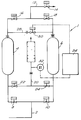
- a PSA plant 1 for the production of oxygen from air includes an air feed line 2 from a compressor (not shown).
- the air feed line 2 is able to be placed in communication with either one of vessels 4, 6 containing beds of a zeolite molecular sieve adsorbent.
- a valve 8 is operable to place the bottom of vessel 4 in communication with the air feed line 2 or deny such communication.
- a valve 10 is operable to place the bottom of vessel 6 in communication with the air feed line 2 or deny such communication.
- the plant 1 includes an outlet pipe 12 for oxygen rich product gas in which is located a valve 14. Valves 16, 18 are operable to place the top of the vessels 4 and 6 respectively in communication with or to deny communication with the pipeline 12.
- the pipeline 12 extends towards an oxygen receiver vessel (not shown).
- the plant 1 includes an outlet pipeline 20 for waste and purge gases.
- a valve 22 is operable to place the bottom of the vessel 4 in communication with the pipeline 20 or deny such communication.
- a valve 24 is operable to place the bottom of the bed 6 in communication with the pipeline 20 or to deny such communication.
- a pipeline 28 connects together the upper ends of the vessels 4, 6 and a valve 30 controls the flow of gas between said vessels 4, 6 through the pipeline 28.
- a fast response analyser sensing head for example, a fuel cell, for sensing the percentage by volume of oxygen flowing through the pipeline 20.
- the fuel cell 32 is located such that in operation it can analyse the gas flowing through the pipeline 20 and generate a signal which is transmitted to a control unit 34.
- the control unit 34 is linked to the valve 30 to permit or prevent the flow of purge gas through the pipeline 28 as will be explained.
- the interior of the vessel 4 is exposed to feed air under pressure which flows from the compressor (not shown) through the pipeline 2 open valve 8 and into the bottom of the pressure vessel 4.
- Nitrogen is adsorbed by the zeolite bed and a product gas rich in oxygen leaves the vessel 4 through the valve 16 and into the pipeline 12; through the valve 14 and into, for example, an oxygen receiver vessel (not shown).
- the zeolite in vessel 4 Whilst the zeolite in vessel 4 is on an adsorption step the zeolite in vessel 6 is undergoing a desorption step in which the bottom of the vessel 6 is in communication with atmosphere via open valve 24 and pipeline 20. Thus, residual unadsorbed gas is vented and adsorbed gas, mainly nitrogen, is desorbed and also vented.
- adsorbed gas mainly nitrogen
- a continuous controlled purge flows through valve 30 such that oxygen rich product gas flows from vessel 4, through line 28 and open valve 30 and hence into the upper end of vessel 6.
- the purging gas will flow down through the vessel 6, through open valve 24 and into line 20 and hence to atmosphere.
- the oxygen purge flow displaces nitrogen in the desorbing bed within the vessel 6.
- the purge step will continue until the fuel cell 32 senses that the percentage by volume of oxygen in the purge gas flowing through the line 20 has reached a preselected level. Once that level is reached the fuel cell 32 will transmit a signal to the controller 34 which will automatically close the valve 30 and interrupt the flow of purge gas through the line 28.
- the zeolite in the vessels 4, 6 will undergo an equalisation step where oxygen rich air will transfer from the higher pressure bed 4 via valves 16, 18 to bed 6. Then the zeolite will reverse roles such that the feed air under pressure will then pass through the feed air line 2 and be directed through open valve 10 and into the bottom of the vessel 6. An oxygen rich product gas leaves the vessel 6 via open valve 18 and passes along the pipeline 12 and open valve 14 towards the oxygen receiver vessel.
- the zeolite in vessel 4 will be desorbed by opening valve 22 such that unadsorbed oxygen and adsorbed nitrogen leaves the bottom of the vessel 4 via open valve 22 and line 20 and a continuous controlled purge will flow from vessel 6 through line 28 and open valve 30 and hence into the upper end of vessel 4.
- the purging gas will flow down through the vessel 6, through open valve 22 into line 20 and hence to atmosphere.
- the oxygen purge flow displaces nitrogen in the desorbing bed within the vessel 4.
- the purging step will continue until the fuel cell 32 senses that the percentage by volume of oxygen in the purge gas flowing through line 20 has reached a preselected level and once that level is reached it will transmit a signal to the controller 34 thereby to close valve 30.
- the system has also been found to be of great advantage in power saving when turndown/load following is used (reduction in product take off which then requires less purge gas hence less power).
- a vacuum pump can be placed in communication with pipeline 20 in a manner known per se .
Claims (5)
- Procédé de production d'un gaz de production à partir d'un mélange de gaz d'alimentation renfermant le gaz de production, comprenant l'exécution répétée d'un cycle d'opérations qui comprend les étapes consistant à :(a) mettre en contact le mélange de gaz d'alimentation avec un lit de matériau adsorbant qui adsorbe préférentiellement au moins un composant du mélange de gaz d'alimentation autre que le gaz de production ;(b) désorber le lit à contre-courant ;(c) purger le lit avec un gaz de purge comprenant le composant non adsorbé du gaz d'alimentation et évacuer ledit gaz de purge dans l'atmosphère ;(d) détecter le moment où le gaz quittant le lit pendant l'étape de purge contient un pourcentage en volume présélectionné du dit gaz de purge ; et(e) lorsqu'est atteint le pourcentage en volume présélectionné, arrêter l'étape de purge.
- Procédé selon la Revendication 1, dans lequel se trouvent une pluralité de ces lits de matériau adsorbant, chacun fonctionnant sur un cycle similaire, mais séquencés pour être déphasés les uns par rapport aux autres de telle façon qu'une alimentation substantiellement continue en gaz de production soit produite.
- Procédé selon la Revendication 1 ou 2, dans lequel le mélange de gaz d'alimentation est l'air et le gaz de production est l'oxygène.
- Dispositif pour la production d'un gaz de production sous forme d'un composant non adsorbé d'un mélange de gaz d'alimentation renfermant le gaz de production par adsorption à pression alternée, comprenant une cuve (4,6) contenant un lit d'adsorbant, ladite cuve (4,6) ayant une première canalisation d'entrée (2) à une de ses zones d'extrémité en communication avec une source du mélange de gaz d'alimentation sous pression, une première canalisation de sortie (20) pour évacuer vers l'atmosphère les gaz désorbés du lit, et à, ou adjacente à, son autre zone d'extrémité une seconde canalisation de sortie (12) pour ledit gaz de production et une seconde canalisation d'entrée (28) pour un gaz de purge, chacune desdites canalisations possédant une vanne (14, 30) pour contrôler l'écoulement de gaz à travers elles ; et un moyen (32) pour détecter le moment où le pourcentage de gaz de purge dans la première canalisation de sortie (20) atteint un pourcentage en volume présélectionné, le moyen de détection transmettant un signal à une unité de contrôle (34) qui, à son tour, ferme la vanne (30) associée à la seconde canalisation d'entrée (28), empêchant ainsi l'écoulement du gaz de purge dans celle-ci.
- Dispositif selon la Revendication 4, dans lequel le moyen de détection (22) est une cellule électrochimique située dans la première canalisation de sortie (20).
Applications Claiming Priority (3)
| Application Number | Priority Date | Filing Date | Title |
|---|---|---|---|
| GB9301904 | 1993-01-30 | ||
| GB939301904A GB9301904D0 (en) | 1993-01-30 | 1993-01-30 | Gas separation |
| US08/189,008 US5490871A (en) | 1993-01-30 | 1994-01-28 | Gas separation |
Publications (2)
| Publication Number | Publication Date |
|---|---|
| EP0609620A1 EP0609620A1 (fr) | 1994-08-10 |
| EP0609620B1 true EP0609620B1 (fr) | 1999-02-10 |
Family
ID=26302366
Family Applications (1)
| Application Number | Title | Priority Date | Filing Date |
|---|---|---|---|
| EP93309809A Expired - Lifetime EP0609620B1 (fr) | 1993-01-30 | 1993-12-07 | Séparation de gaz |
Country Status (7)
| Country | Link |
|---|---|
| US (1) | US5490871A (fr) |
| EP (1) | EP0609620B1 (fr) |
| JP (1) | JPH07745A (fr) |
| CN (1) | CN1103601A (fr) |
| AU (1) | AU658087B2 (fr) |
| CA (1) | CA2112959A1 (fr) |
| ZA (1) | ZA94214B (fr) |
Families Citing this family (22)
| Publication number | Priority date | Publication date | Assignee | Title |
|---|---|---|---|---|
| US5529607A (en) * | 1995-03-15 | 1996-06-25 | The Boc Group, Inc. | PSA process with dynamic purge control |
| US5906672A (en) * | 1996-06-14 | 1999-05-25 | Invacare Corporation | Closed-loop feedback control for oxygen concentrator |
| US5858062A (en) * | 1997-02-10 | 1999-01-12 | Litton Systems, Inc. | Oxygen concentrator |
| US5979440A (en) | 1997-06-16 | 1999-11-09 | Sequal Technologies, Inc. | Methods and apparatus to generate liquid ambulatory oxygen from an oxygen concentrator |
| US5871564A (en) * | 1997-06-16 | 1999-02-16 | Airsep Corp | Pressure swing adsorption apparatus |
| US7204249B1 (en) | 1997-10-01 | 2007-04-17 | Invcare Corporation | Oxygen conserving device utilizing a radial multi-stage compressor for high-pressure mobile storage |
| US5988165A (en) | 1997-10-01 | 1999-11-23 | Invacare Corporation | Apparatus and method for forming oxygen-enriched gas and compression thereof for high-pressure mobile storage utilization |
| US6167947B1 (en) * | 1998-12-18 | 2001-01-02 | Silicon Graphics, Inc. | High performance gas cooling system and method |
| DE10152359A1 (de) * | 2001-10-24 | 2003-05-08 | Linde Ag | Molsiebstation |
| US6709486B2 (en) * | 2002-04-08 | 2004-03-23 | Air Products And Chemicals, Inc. | Pressure swing adsorption process with controlled internal depressurization flow |
| KR100491684B1 (ko) * | 2002-04-12 | 2005-05-30 | 주식회사 옥서스 | 압력순환흡착을 이용한 산소농축방법 및 장치 |
| GB0230098D0 (en) * | 2002-12-24 | 2003-01-29 | Honeywell Normalair Garrett | Method of controlling a gas absorption apparatus |
| DE102004026650B4 (de) * | 2004-06-01 | 2007-11-29 | DRäGER AEROSPACE GMBH | Verfahren zum Betreiben einer Luftzerlegungsanlage zur Gewinnung von Sauerstoff an Bord eines Flugzeugs |
| US8062003B2 (en) * | 2005-09-21 | 2011-11-22 | Invacare Corporation | System and method for providing oxygen |
| US7771511B2 (en) | 2006-08-28 | 2010-08-10 | Ric Investments, Llc | Oxygen concentration system and method |
| IT1395955B1 (it) * | 2009-06-19 | 2012-11-02 | Parker Hannifin Srl | "procedimento e apparecchio per l'essicazione di gas compresso" |
| US20110038740A1 (en) * | 2009-08-17 | 2011-02-17 | Invacare Corporation | Compressor |
| US9624918B2 (en) | 2012-02-03 | 2017-04-18 | Invacare Corporation | Pumping device |
| US9873078B2 (en) | 2013-02-15 | 2018-01-23 | Koninklijke Philips N.V | Oxygen separator and method of generating oxygen |
| US20210275771A1 (en) * | 2016-07-08 | 2021-09-09 | Oxigear Corporation | Apparatus and methods for cleaning and oxygen-enriching air |
| WO2018178663A1 (fr) * | 2017-03-30 | 2018-10-04 | Parker Hannifin Manufacturing Limited | Système d'adsorption modulée en pression à limiteur d'écoulement variable |
| US10695710B2 (en) * | 2018-08-02 | 2020-06-30 | Messer Industries Usa, Inc. | Methods for producing ozone and oxygen mixtures |
Family Cites Families (17)
| Publication number | Priority date | Publication date | Assignee | Title |
|---|---|---|---|---|
| US3775946A (en) * | 1972-10-13 | 1973-12-04 | Howe Baker Eng | Adsorption control |
| US4197095A (en) * | 1978-08-31 | 1980-04-08 | Pall Corporation | Heatless adsorbent fractionators with microprocessor cycle control and process |
| DE2930782A1 (de) * | 1979-07-28 | 1981-02-12 | Linde Ag | Verfahren zur adsorptiven reinigung oder zerlegung von gasgemischen |
| US4440548A (en) * | 1982-04-19 | 1984-04-03 | Calgon Carbon Corporation | Pressure swing absorption system |
| US4648888A (en) * | 1982-07-09 | 1987-03-10 | Hudson Oxygen Therapy Sales Co. | Oxygen concentrator |
| US4472177A (en) * | 1982-09-09 | 1984-09-18 | Air Products And Chemicals, Inc. | Control system and method for air fractionation by vacuum swing adsorption |
| US4631073A (en) * | 1984-03-15 | 1986-12-23 | Wilkerson Corporation | Method and apparatus for theadsorptive fractionation of gases |
| JPS61183121U (fr) * | 1985-05-07 | 1986-11-15 | ||
| JPS6297622A (ja) * | 1985-10-23 | 1987-05-07 | Kobe Steel Ltd | 圧力スイング吸着方法 |
| US4693730A (en) * | 1986-07-24 | 1987-09-15 | Union Carbide Corporation | Pressure swing adsorption product purity control method and apparatus |
| JP2683806B2 (ja) * | 1988-03-17 | 1997-12-03 | 住友精化株式会社 | 濃縮酸素回収方法 |
| DE3827228A1 (de) * | 1988-08-11 | 1990-02-15 | Standard Elektrik Lorenz Ag | Sende/empfangsteil fuer ein bidirektionales kohaerent-optisches uebertragungssystem |
| US5071453A (en) * | 1989-09-28 | 1991-12-10 | Litton Systems, Inc. | Oxygen concentrator with pressure booster and oxygen concentration monitoring |
| US5032150A (en) * | 1989-11-03 | 1991-07-16 | The Ohio State University | Pressure swing adsorption |
| US5163978A (en) * | 1991-10-08 | 1992-11-17 | Praxair Technology, Inc. | Dual product pressure swing adsorption process and system |
| US5207806A (en) * | 1991-10-08 | 1993-05-04 | Praxair Technology, Inc. | Dual product pressure swing adsorption and membrane operations |
| JP2502260B2 (ja) * | 1993-04-19 | 1996-05-29 | 日本石油化学株式会社 | 配管被覆用複合シ―トおよび該シ―トを用いた樹脂配管の遮音方法 |
-
1993
- 1993-12-07 EP EP93309809A patent/EP0609620B1/fr not_active Expired - Lifetime
- 1993-12-28 JP JP5355115A patent/JPH07745A/ja active Pending
-
1994
- 1994-01-06 CA CA002112959A patent/CA2112959A1/fr not_active Abandoned
- 1994-01-12 ZA ZA94214A patent/ZA94214B/xx unknown
- 1994-01-17 AU AU53827/94A patent/AU658087B2/en not_active Ceased
- 1994-01-28 US US08/189,008 patent/US5490871A/en not_active Expired - Fee Related
- 1994-01-29 CN CN94101208A patent/CN1103601A/zh active Pending
Also Published As
| Publication number | Publication date |
|---|---|
| JPH07745A (ja) | 1995-01-06 |
| CA2112959A1 (fr) | 1994-07-31 |
| AU658087B2 (en) | 1995-03-30 |
| ZA94214B (en) | 1994-08-22 |
| CN1103601A (zh) | 1995-06-14 |
| AU5382794A (en) | 1994-08-18 |
| US5490871A (en) | 1996-02-13 |
| EP0609620A1 (fr) | 1994-08-10 |
Similar Documents
| Publication | Publication Date | Title |
|---|---|---|
| EP0609620B1 (fr) | Séparation de gaz | |
| US4576614A (en) | Process and apparatus for separation of a gaseous mixture | |
| CA2162346C (fr) | Methode d'absorption modulee en pression | |
| US5882380A (en) | Pressure swing adsorption process with a single adsorbent bed | |
| US4494966A (en) | Process for nitrogen enrichment | |
| US5486226A (en) | Separation of gaseous mixtures | |
| US6245127B1 (en) | Pressure swing adsorption process and apparatus | |
| US5906674A (en) | Process and apparatus for separating gas mixtures | |
| US4959083A (en) | Separation of gas mixtures | |
| US5441558A (en) | High purity nitrogen PSA utilizing controlled internal flows | |
| US3977845A (en) | Adsorptive process for selective separation of gases | |
| CA2255526C (fr) | Processus et systeme amp d'evacuation simultanee aux niveaux superieur et inferieur de lit adsorbant | |
| US6045603A (en) | Two phase pressure swing adsorption process | |
| JPH04330913A (ja) | ガス混合物を分離するための吸着方法 | |
| CA2366266A1 (fr) | Procede d'epuration de l'argon | |
| JPH05261233A (ja) | 窒素ガス分離方法 | |
| EP0147277A2 (fr) | Procédé de séparation d'un courant d'alimentation d'un mélange gazeux par adsorption à pression alternée | |
| GB2109266A (en) | Pressure swing process for the separation of gas mixtures by adsorption | |
| US6270556B1 (en) | PSA or VSA unit having jointly-controlled production output and production pressure | |
| GB2073043A (en) | Separation of a gaseous mixture | |
| CA1182765A (fr) | Repressurisation pour systeme d'adsorption a pression oscillante | |
| JPH0532087B2 (fr) | ||
| GB2161717A (en) | Improved apparatus for the separation of a gaseous mixture | |
| GB2195097A (en) | Separation of gas mixtures by pressure swing adsorption | |
| GB2163669A (en) | Apparatus for the separation of a gaseous mixture by pressure swing adsorption (PSA) |
Legal Events
| Date | Code | Title | Description |
|---|---|---|---|
| PUAI | Public reference made under article 153(3) epc to a published international application that has entered the european phase |
Free format text: ORIGINAL CODE: 0009012 |
|
| AK | Designated contracting states |
Kind code of ref document: A1 Designated state(s): BE DE FR GB IE IT NL |
|
| 17P | Request for examination filed |
Effective date: 19940818 |
|
| 17Q | First examination report despatched |
Effective date: 19951220 |
|
| GRAG | Despatch of communication of intention to grant |
Free format text: ORIGINAL CODE: EPIDOS AGRA |
|
| GRAG | Despatch of communication of intention to grant |
Free format text: ORIGINAL CODE: EPIDOS AGRA |
|
| GRAG | Despatch of communication of intention to grant |
Free format text: ORIGINAL CODE: EPIDOS AGRA |
|
| GRAH | Despatch of communication of intention to grant a patent |
Free format text: ORIGINAL CODE: EPIDOS IGRA |
|
| GRAH | Despatch of communication of intention to grant a patent |
Free format text: ORIGINAL CODE: EPIDOS IGRA |
|
| GRAA | (expected) grant |
Free format text: ORIGINAL CODE: 0009210 |
|
| AK | Designated contracting states |
Kind code of ref document: B1 Designated state(s): BE DE FR GB IE IT NL |
|
| PG25 | Lapsed in a contracting state [announced via postgrant information from national office to epo] |
Ref country code: NL Free format text: LAPSE BECAUSE OF FAILURE TO SUBMIT A TRANSLATION OF THE DESCRIPTION OR TO PAY THE FEE WITHIN THE PRESCRIBED TIME-LIMIT Effective date: 19990210 Ref country code: IT Free format text: LAPSE BECAUSE OF FAILURE TO SUBMIT A TRANSLATION OF THE DESCRIPTION OR TO PAY THE FEE WITHIN THE PRE;WARNING: LAPSES OF ITALIAN PATENTS WITH EFFECTIVE DATE BEFORE 2007 MAY HAVE OCCURRED AT ANY TIME BEFORE 2007. THE CORRECT EFFECTIVE DATE MAY BE DIFFERENT FROM THE ONE RECORDED.SCRIBED TIME-LIMIT Effective date: 19990210 Ref country code: BE Free format text: LAPSE BECAUSE OF FAILURE TO SUBMIT A TRANSLATION OF THE DESCRIPTION OR TO PAY THE FEE WITHIN THE PRESCRIBED TIME-LIMIT Effective date: 19990210 |
|
| ET | Fr: translation filed | ||
| REG | Reference to a national code |
Ref country code: IE Ref legal event code: FG4D |
|
| REF | Corresponds to: |
Ref document number: 69323481 Country of ref document: DE Date of ref document: 19990325 |
|
| NLV1 | Nl: lapsed or annulled due to failure to fulfill the requirements of art. 29p and 29m of the patents act | ||
| PG25 | Lapsed in a contracting state [announced via postgrant information from national office to epo] |
Ref country code: IE Free format text: LAPSE BECAUSE OF NON-PAYMENT OF DUE FEES Effective date: 19991207 |
|
| PLBE | No opposition filed within time limit |
Free format text: ORIGINAL CODE: 0009261 |
|
| STAA | Information on the status of an ep patent application or granted ep patent |
Free format text: STATUS: NO OPPOSITION FILED WITHIN TIME LIMIT |
|
| 26N | No opposition filed | ||
| REG | Reference to a national code |
Ref country code: IE Ref legal event code: MM4A |
|
| PGFP | Annual fee paid to national office [announced via postgrant information from national office to epo] |
Ref country code: FR Payment date: 20011120 Year of fee payment: 9 |
|
| PGFP | Annual fee paid to national office [announced via postgrant information from national office to epo] |
Ref country code: GB Payment date: 20011122 Year of fee payment: 9 |
|
| PGFP | Annual fee paid to national office [announced via postgrant information from national office to epo] |
Ref country code: DE Payment date: 20011123 Year of fee payment: 9 |
|
| REG | Reference to a national code |
Ref country code: GB Ref legal event code: IF02 |
|
| PG25 | Lapsed in a contracting state [announced via postgrant information from national office to epo] |
Ref country code: GB Free format text: LAPSE BECAUSE OF NON-PAYMENT OF DUE FEES Effective date: 20021207 |
|
| PG25 | Lapsed in a contracting state [announced via postgrant information from national office to epo] |
Ref country code: DE Free format text: LAPSE BECAUSE OF NON-PAYMENT OF DUE FEES Effective date: 20030701 |
|
| GBPC | Gb: european patent ceased through non-payment of renewal fee | ||
| PG25 | Lapsed in a contracting state [announced via postgrant information from national office to epo] |
Ref country code: FR Free format text: LAPSE BECAUSE OF NON-PAYMENT OF DUE FEES Effective date: 20030901 |
|
| REG | Reference to a national code |
Ref country code: FR Ref legal event code: ST |