EP0609593B1 - Optische Filter - Google Patents
Optische Filter Download PDFInfo
- Publication number
- EP0609593B1 EP0609593B1 EP93300794A EP93300794A EP0609593B1 EP 0609593 B1 EP0609593 B1 EP 0609593B1 EP 93300794 A EP93300794 A EP 93300794A EP 93300794 A EP93300794 A EP 93300794A EP 0609593 B1 EP0609593 B1 EP 0609593B1
- Authority
- EP
- European Patent Office
- Prior art keywords
- refractive index
- layer
- optical
- coating
- optical filter
- Prior art date
- Legal status (The legal status is an assumption and is not a legal conclusion. Google has not performed a legal analysis and makes no representation as to the accuracy of the status listed.)
- Expired - Lifetime
Links
- 230000003287 optical effect Effects 0.000 title claims description 40
- 238000000576 coating method Methods 0.000 claims description 30
- 239000011248 coating agent Substances 0.000 claims description 29
- 239000000463 material Substances 0.000 claims description 22
- 230000005540 biological transmission Effects 0.000 claims description 14
- 230000005855 radiation Effects 0.000 claims description 14
- 239000011521 glass Substances 0.000 claims description 9
- 239000000758 substrate Substances 0.000 claims description 8
- 238000010521 absorption reaction Methods 0.000 claims description 7
- 239000005083 Zinc sulfide Substances 0.000 claims description 6
- MZQZQKZKTGRQCG-UHFFFAOYSA-J thorium tetrafluoride Chemical compound F[Th](F)(F)F MZQZQKZKTGRQCG-UHFFFAOYSA-J 0.000 claims description 6
- DRDVZXDWVBGGMH-UHFFFAOYSA-N zinc;sulfide Chemical compound [S-2].[Zn+2] DRDVZXDWVBGGMH-UHFFFAOYSA-N 0.000 claims description 6
- 230000001464 adherent effect Effects 0.000 claims description 2
- 230000002401 inhibitory effect Effects 0.000 claims description 2
- 239000004568 cement Substances 0.000 description 4
- VYPSYNLAJGMNEJ-UHFFFAOYSA-N Silicium dioxide Chemical compound O=[Si]=O VYPSYNLAJGMNEJ-UHFFFAOYSA-N 0.000 description 2
- GWEVSGVZZGPLCZ-UHFFFAOYSA-N Titan oxide Chemical compound O=[Ti]=O GWEVSGVZZGPLCZ-UHFFFAOYSA-N 0.000 description 2
- 230000000903 blocking effect Effects 0.000 description 2
- 238000001429 visible spectrum Methods 0.000 description 2
- 238000004519 manufacturing process Methods 0.000 description 1
- -1 rare earth fluorides Chemical class 0.000 description 1
- 229910052761 rare earth metal Inorganic materials 0.000 description 1
- 229910001404 rare earth metal oxide Inorganic materials 0.000 description 1
- 150000003346 selenoethers Chemical class 0.000 description 1
- 239000000377 silicon dioxide Substances 0.000 description 1
- 238000001228 spectrum Methods 0.000 description 1
- 150000004763 sulfides Chemical class 0.000 description 1
Images
Classifications
-
- G—PHYSICS
- G02—OPTICS
- G02B—OPTICAL ELEMENTS, SYSTEMS OR APPARATUS
- G02B5/00—Optical elements other than lenses
- G02B5/20—Filters
- G02B5/28—Interference filters
- G02B5/285—Interference filters comprising deposited thin solid films
Definitions
- This invention relates to optical filters and in particular to a filter in the form of a multi-layer coating on a substrate.
- the optical device may be a pair of goggles (or spectacles) to be worn by a human observer and on the one hand there is a need for the goggles to transmit radiation generally over the visible spectrum whilst on the other hand there is a need to protect the observers eyes from damaging laser radiation which may occur at one or more of at least three particularly-favoured laser radiation wavelengths.
- an optical filter for inhibiting transmission of radiation at at least one wavelength which is known to be a laser wavelength in the form of a multi-layer coating adherent to a substrate, said coating comprising a plurality of superimposed layer collections, said plurality being n in number where n is at least four, each layer collection consisting of ordered first second and third layers, said first and third layers each being made of a first optical coating material and having a thickness of substantially 0.6 quarter wavelengths at a predetermined wavelength, said second layer being made of a second optical coating material and having a thickness of substantially 6.8 quarter wavelengths at said predetermined wavelength, one of said first and second optical coating materials having a high refractive index and the other of said optical coating materials having a low refractive index, whereby the coating is generally transmissive except in a plurality of narrow-waveband regions, said predetermined wavelength being selected so that at least one of said regions includes said known laser wavelength.
- the number n may be in the range 4 to about 20 (being limited at the upper end of the range by manufacturing processes) and the greater the value of n the less is the transmission within said narrow-waveband regions.
- the first layer of each said layer collection may be composed of said high refractive index material.
- the first layer of each said layer collection may be composed of said low refractive index material.
- Typical high refractive index optical coating materials have refractive indices in the range 1.9 to 2.5 and are: zinc sulphide, titania, certain rare earth oxides and certain sulphides and selenides.
- Typical low refractive index optical coating materials have refractive indices in the range 1.3 to 1.7 and are: thorium fluoride, silica, certain rare earth fluorides and certain oxides.
- the optical filter of the present invention may be one of a pair of spaced filters separated by a medium which preferably possesses absorption properties as a result of which the combination exhibits improved rejection efficiency within the narrow-waveband regions in comparison with a single coating with a given value of n . Also, in this arrangement it is preferred that each optical coating material possesses a small but finite degree of absorption since this attenuates multiple reflections between the coatings and improves the rejection efficiency within the narrow-waveband regions for a given value of n .
- the optical filter of the present invention provides rejection of incident laser radiation.
- the rejection efficiency for normal incidence of the laser radiation on the filter is substantially maintained for incidence angles within a limited angular range the magnitude of which is determined by the width of the narrow-waveband region of the coating, because at non-normal incidence the coating characteristics effectively shift spectrally downwards in proportion to the angle of incidence.
- the coating of the optical filter of the present invention may be index-matched to its adjoining media.
- the filter of the present invention may incorporate a substrate in the form of a colour glass for rejecting a particular wavelength or narrow-waveband region to which the multi-layer coating is transmissive.
- the substrate is clear glass and the coating is composed of superimposed layer collections each of which has first and third layers made of zinc sulphide and a second layer made of thorium fluoride.
- the zinc sulphide layers are each 0.6 quarter wavelengths thick at a predetermined wavelength and the thorium fluoride layer is 6.8 quarter wavelengths thick at said predetermined wavelength.
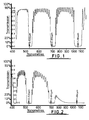
- a transmission characteristic of an optical filter is shown in Fig.
- the optical density of the filter provides effective blocking protection against transmission of laser radiation for a range of incidence angles of the order of ⁇ 22° with an overall transmission efficiency of the order of 50% elsewhere in the visible spectrum as measured by the conventional integrated visible photopic transmission factor F, where T( ⁇ ) being filter transmission with respect to wavelength ⁇ ; E( ⁇ ) being the photopic eye response as a function of wavelength ⁇ ; E(D65) being the response of the standard D65 illuminant as a function of wavelength ⁇ .
- two filters of the Table I type are cemented together with a non-absorbing optical cement, namely Norland Inc. cement designation No. NOA61 and the combined filter arrangement displays improved characteristics as set forth in Table II, the angular range values given being for simultaneous effective protection at the three laser radiation wavelengths.
- the improvement in optical density within the narrow-waveband region is relatively marginal (e.g. if the optical density of a filter is 4.0 the optical density of a combined filter is 4.3). If an absorption medium is utilised between the two filters, such as Schott NG 12 neutrally absorbing glass which has an absorption of about 10%, the optical density of the combined filter is 7.3. Where the optical coating materials of each filter possess an absorption of about 0.5%, as in the Table II embodiment, the optical density of the combined filter is 6.0. In both cases the overall transmission factor remains of the order of 40-50%.
- the materials are the same as in the first embodiment and the layer collections are the same in number but the first and third layers are made of thorium fluoride whilst the second layer is made of zinc sulphide.
- the thorium fluoride layers of the third embodiment are each 0.6 quarter wavelength thick at a wavelength of 0.543 »m and the zinc sulphide layers are each 6.8 quarter wavelengths thick at the same 0.543 »m wavelength.
- Quantitative values of transmission parameters are set forth in Table III for the third embodiment, and in comparison with the Table I values for the first embodiment it will be observed that there is very little difference.
- the first embodiment has its angular performance limited by the coating behaviour at 0.532 »m whereas the third embodiment has its angular performance limited by the coating behaviour at 1.064 »m and colour glasses are readily available which are effectively non-transmitting at 1.064 »m but which are substantially fully transmitting at the visible region of the spectrum.
- a fourth and preferred embodiment is therefore provided by the third embodiment modified by a colour glass, either as a substitute for or in addition to the clear glass substrate, of 2.5 mm thickness and made of LP3 colour glass (made and sold by Chance - Pilkington Ltd.).
- Quantitative values of transmission parameters are set forth in Table IV for the fourth embodiment and the transmission characteristic of this optical filter is shown in Fig. 2. It will be appreciated that the fourth embodiment provides substantially improved angular performance and provides effective blocking protection for a range of incidence angles of the order of ⁇ 38° and overall transmission efficiency (F) of the order of 42%.
- one filter of the Table III type and one filter of the Table IV type are cemented together with the same cement as in the second embodiment, and the combined filter arrangement displays the characteristics set forth in Table VI.
Landscapes
- Physics & Mathematics (AREA)
- General Physics & Mathematics (AREA)
- Optics & Photonics (AREA)
- Optical Filters (AREA)
Claims (8)
- Optisches Filter zur Unterbindung der Übertragung von Strahlung bei wenigstens einer Wellenlänge, die als eine Laser-Wellenlänge bekannt ist, in Form eines mehrschichtigen Überzugs, der an einem Substrat haftet, wobei der Überzug eine Vielzahl von sich überlagernden Schichtansammlungen umfaßt, wobei die Vielzahl gleich der Zahl n ist, wenn n wenigstens gleich vier ist, wobei jede Schichtansammlung aus geordneten ersten, zweiten und dritten Schichten besteht, wobei die erste und die dritte Schicht jeweils aus einem ersten optischen Beschichtungsmaterial hergestellt werden und eine Stärke von im wesentlichen 0,6 Viertelwellenlängen bei einer festgelegten Wellenlänge haben, wobei die zweite Schicht aus einem zweiten optischen Beschichtungsmaterial herstellt wird und eine Stärke von im wesentlichen 6,8 Viertelwellenlängen bei der festgelegten Wellenlänge hat, wobei eines der ersten und der zweiten optischen Beschichtsmaterialien einen hohen Brechungskoeffizienten hat und das andere der optischen Beschichtungsmaterialien einen niedrigen Brechungskoeffizienten hat, wodurch der Überzug allgemein durchlässig ist, ausgenommen eine Vielzahl von schmalbandigen Wellenbereichen, wobei die festgelegte Wellenlänge so ausgewählt wird, daß wenigstens einer der Bereiche die bekannte Laser-Wellenlänge einschließt.
- Optisches Filter nach Anspruch 1, bei dem das Material mit dem hohen Brechungskoeffizienten einen Brechungskoeffizienten im Bereich von 1,9 bis 2,5 hat und das Material mit dem niedrigen Brechungskoeffizienten einen Brechungskoeffizienten im Bereich von 1,3 bis 1,7 hat.
- Optisches Filter nach einem der vorhergehenden Ansprüche, bei dem das Material mit dem hohen Brechungskoeffizienten Zinksulfid ist und das Material mit dem niedrigen Brechungskoeffizienten Thoriumfluorid ist.
- Optisches Filter nach einem der Ansprüche 1 bis 3, bei dem sich die erste Schicht jeder der Schichtansammlungen aus dem Material mit dem hohen Brechungskoeffizienten zusammensetzt.
- Optisches Filter nach einem der Ansprüche 1 bis 3, bei dem sich die erste Schicht jeder der Schichtansammlungen aus dem Material mit dem niedrigen Brechungskoeffizienten zusammensetzt.
- Optisches Filter nach einem der vorhergehenden Ansprüche, bei dem das Substrat aus farblosem Glas hergestellt wird.
- Optisches Filter nach einem der Ansprüche 1 bis 5, bei dem das Substrat aus Farbglas hergestellt wird, das einen schmalen Wellenband-Bereich zurückweist, für den der mehrschichtige Überzug durchlässig ist.
- Optische Filterbaugruppe, die ein Paar im Abstand zueinander angeordneter optischer Filter jeweils nach Anspruch 1 aufweist und die durch ein Medium mit Absorptionseigenschaften voneinander getrennt sind.
Priority Applications (5)
| Application Number | Priority Date | Filing Date | Title |
|---|---|---|---|
| US06/947,514 US5399298A (en) | 1985-11-01 | 1986-10-27 | Optical filters with coatings transmissive in narrow waveband regions |
| GB8625623A GB2261523B (en) | 1985-11-01 | 1986-10-27 | Optical filters |
| DE1993601085 DE69301085T2 (de) | 1993-02-03 | 1993-02-03 | Optische Filter |
| EP93300794A EP0609593B1 (de) | 1985-11-01 | 1993-02-03 | Optische Filter |
| NO930435A NO307234B1 (no) | 1985-11-01 | 1993-02-08 | Optisk filter |
Applications Claiming Priority (4)
| Application Number | Priority Date | Filing Date | Title |
|---|---|---|---|
| GB858527000A GB8527000D0 (en) | 1985-11-01 | 1985-11-01 | Optical filters |
| GB8625623A GB2261523B (en) | 1985-11-01 | 1986-10-27 | Optical filters |
| EP93300794A EP0609593B1 (de) | 1985-11-01 | 1993-02-03 | Optische Filter |
| NO930435A NO307234B1 (no) | 1985-11-01 | 1993-02-08 | Optisk filter |
Publications (2)
| Publication Number | Publication Date |
|---|---|
| EP0609593A1 EP0609593A1 (de) | 1994-08-10 |
| EP0609593B1 true EP0609593B1 (de) | 1995-12-20 |
Family
ID=27442640
Family Applications (1)
| Application Number | Title | Priority Date | Filing Date |
|---|---|---|---|
| EP93300794A Expired - Lifetime EP0609593B1 (de) | 1985-11-01 | 1993-02-03 | Optische Filter |
Country Status (3)
| Country | Link |
|---|---|
| EP (1) | EP0609593B1 (de) |
| GB (1) | GB2261523B (de) |
| NO (1) | NO307234B1 (de) |
Cited By (6)
| Publication number | Priority date | Publication date | Assignee | Title |
|---|---|---|---|---|
| US7515336B2 (en) | 2001-12-21 | 2009-04-07 | Bose Corporation | Selective reflecting |
| US7517091B2 (en) | 2005-05-12 | 2009-04-14 | Bose Corporation | Color gamut improvement in presence of ambient light |
| US7520624B2 (en) | 2001-12-21 | 2009-04-21 | Bose Corporation | Light enhancing |
| US7535636B2 (en) | 2001-12-21 | 2009-05-19 | Bose Corporation | Selective reflecting |
| US7710645B2 (en) | 2007-06-29 | 2010-05-04 | Bose Corporation | Selective reflecting for laser projector |
| US8081368B2 (en) | 2007-03-29 | 2011-12-20 | Bose Corporation | Selective absorbing |
Families Citing this family (4)
| Publication number | Priority date | Publication date | Assignee | Title |
|---|---|---|---|---|
| JP2002055212A (ja) * | 2000-08-08 | 2002-02-20 | Sumitomo Electric Ind Ltd | プリズムとそれを用いた光学装置 |
| WO2002016976A2 (en) | 2000-08-21 | 2002-02-28 | 3M Innovative Properties Company | Loss enhanced reflective optical filters |
| WO2016085767A1 (en) * | 2014-11-30 | 2016-06-02 | Perriquest Defense Research Enterprises, Llc | Spectrally filtered eyewear |
| CN106842793A (zh) * | 2017-02-16 | 2017-06-13 | 深圳市华星光电技术有限公司 | 一种光谱转换器和投影电视光源系统 |
Family Cites Families (4)
| Publication number | Priority date | Publication date | Assignee | Title |
|---|---|---|---|---|
| US2890624A (en) * | 1952-10-07 | 1959-06-16 | Rca Corp | Interference color filter with blue absorbing layers |
| US5233464A (en) * | 1991-03-20 | 1993-08-03 | Costich Verne R | Multilayer infrared filter |
| US5200855A (en) * | 1991-07-12 | 1993-04-06 | Optical Coating Laboratory, Inc. | Absorbing dichroic filters |
| US5179468A (en) * | 1991-11-05 | 1993-01-12 | Gte Products Corporation | Interleaving of similar thin-film stacks for producing optical interference coatings |
-
1986
- 1986-10-27 GB GB8625623A patent/GB2261523B/en not_active Expired - Fee Related
-
1993
- 1993-02-03 EP EP93300794A patent/EP0609593B1/de not_active Expired - Lifetime
- 1993-02-08 NO NO930435A patent/NO307234B1/no not_active IP Right Cessation
Cited By (6)
| Publication number | Priority date | Publication date | Assignee | Title |
|---|---|---|---|---|
| US7515336B2 (en) | 2001-12-21 | 2009-04-07 | Bose Corporation | Selective reflecting |
| US7520624B2 (en) | 2001-12-21 | 2009-04-21 | Bose Corporation | Light enhancing |
| US7535636B2 (en) | 2001-12-21 | 2009-05-19 | Bose Corporation | Selective reflecting |
| US7517091B2 (en) | 2005-05-12 | 2009-04-14 | Bose Corporation | Color gamut improvement in presence of ambient light |
| US8081368B2 (en) | 2007-03-29 | 2011-12-20 | Bose Corporation | Selective absorbing |
| US7710645B2 (en) | 2007-06-29 | 2010-05-04 | Bose Corporation | Selective reflecting for laser projector |
Also Published As
| Publication number | Publication date |
|---|---|
| GB8625623D0 (en) | 1993-03-10 |
| EP0609593A1 (de) | 1994-08-10 |
| NO930435L (no) | 1994-08-09 |
| NO307234B1 (no) | 2000-02-28 |
| NO930435D0 (no) | 1993-02-08 |
| GB2261523A (en) | 1993-05-19 |
| GB2261523B (en) | 1993-12-08 |
Similar Documents
| Publication | Publication Date | Title |
|---|---|---|
| US5399298A (en) | Optical filters with coatings transmissive in narrow waveband regions | |
| US20120099188A1 (en) | Laser Protection Structures and Methods of Fabrication | |
| US6863397B2 (en) | Optical element and eyeglass lens | |
| US4659178A (en) | Optical filter | |
| US2758510A (en) | Interference filter for sunglasses | |
| AU610715B2 (en) | Dielectric layer polarizer | |
| US5561541A (en) | Frustrated total internal reflection optical power limiter | |
| EP0609593B1 (de) | Optische Filter | |
| CA1325741C (en) | Infrared filter using cholesteric liquids | |
| EP0966696B1 (de) | Optisches interferenzfilter | |
| EP2342591B1 (de) | Variabel durchlassendes zusammengesetztes störungsfilter | |
| EP0041358A3 (de) | Nichtpolarisierendes Dünnschichtfilter mit Kantencharakteristik und faseroptisches Nachrichtensystem mit einem solchen Filter | |
| EP0565703A1 (de) | Optischer Interferenzüberzug mit aufeinanderfolgenden Schichtstapeln. | |
| US10928569B2 (en) | Angle-insensitive multi-wavelength optical filters with hue control | |
| EP2859867A1 (de) | Laserschützende Vorrichtung mit reflektierendem Filter auf nichtabsorbierenden und absorbierenden Substraten | |
| US5315437A (en) | Protective device for selectively reflecting high-intensity light over a broad spectral bandwidth | |
| US4487478A (en) | Laser protection device | |
| US5005926A (en) | Ballistic protective laser shield | |
| US20070211359A1 (en) | Neutral white-light filter device | |
| US3504959A (en) | Multi-spike optical filter | |
| FR2800174B1 (fr) | Verre composite de protection de la vue | |
| US5978134A (en) | Low-pass filter for the UV band of the electromagnetic spectrum | |
| JP3894107B2 (ja) | 赤外域用反射防止膜 | |
| CN108828704A (zh) | 一种红外激光隔断光子晶体薄膜 | |
| DE69301085T2 (de) | Optische Filter |
Legal Events
| Date | Code | Title | Description |
|---|---|---|---|
| PUAI | Public reference made under article 153(3) epc to a published international application that has entered the european phase |
Free format text: ORIGINAL CODE: 0009012 |
|
| 17P | Request for examination filed |
Effective date: 19930809 |
|
| AK | Designated contracting states |
Kind code of ref document: A1 Designated state(s): BE CH DE DK ES FR IT LI NL SE |
|
| 17Q | First examination report despatched |
Effective date: 19950411 |
|
| GRAA | (expected) grant |
Free format text: ORIGINAL CODE: 0009210 |
|
| AK | Designated contracting states |
Kind code of ref document: B1 Designated state(s): BE CH DE DK ES FR IT LI NL SE |
|
| PG25 | Lapsed in a contracting state [announced via postgrant information from national office to epo] |
Ref country code: NL Free format text: LAPSE BECAUSE OF FAILURE TO SUBMIT A TRANSLATION OF THE DESCRIPTION OR TO PAY THE FEE WITHIN THE PRESCRIBED TIME-LIMIT Effective date: 19951220 Ref country code: LI Free format text: LAPSE BECAUSE OF FAILURE TO SUBMIT A TRANSLATION OF THE DESCRIPTION OR TO PAY THE FEE WITHIN THE PRESCRIBED TIME-LIMIT Effective date: 19951220 Ref country code: ES Free format text: THE PATENT HAS BEEN ANNULLED BY A DECISION OF A NATIONAL AUTHORITY Effective date: 19951220 Ref country code: DK Effective date: 19951220 Ref country code: CH Free format text: LAPSE BECAUSE OF FAILURE TO SUBMIT A TRANSLATION OF THE DESCRIPTION OR TO PAY THE FEE WITHIN THE PRESCRIBED TIME-LIMIT Effective date: 19951220 Ref country code: BE Effective date: 19951220 |
|
| REF | Corresponds to: |
Ref document number: 69301085 Country of ref document: DE Date of ref document: 19960201 |
|
| ITF | It: translation for a ep patent filed | ||
| PG25 | Lapsed in a contracting state [announced via postgrant information from national office to epo] |
Ref country code: SE Effective date: 19960320 |
|
| ET | Fr: translation filed | ||
| NLV1 | Nl: lapsed or annulled due to failure to fulfill the requirements of art. 29p and 29m of the patents act | ||
| PLBE | No opposition filed within time limit |
Free format text: ORIGINAL CODE: 0009261 |
|
| STAA | Information on the status of an ep patent application or granted ep patent |
Free format text: STATUS: NO OPPOSITION FILED WITHIN TIME LIMIT |
|
| 26N | No opposition filed | ||
| PGFP | Annual fee paid to national office [announced via postgrant information from national office to epo] |
Ref country code: FR Payment date: 20010226 Year of fee payment: 9 |
|
| PGFP | Annual fee paid to national office [announced via postgrant information from national office to epo] |
Ref country code: DE Payment date: 20010228 Year of fee payment: 9 |
|
| PG25 | Lapsed in a contracting state [announced via postgrant information from national office to epo] |
Ref country code: DE Free format text: LAPSE BECAUSE OF NON-PAYMENT OF DUE FEES Effective date: 20020903 |
|
| PG25 | Lapsed in a contracting state [announced via postgrant information from national office to epo] |
Ref country code: FR Free format text: LAPSE BECAUSE OF NON-PAYMENT OF DUE FEES Effective date: 20021031 |
|
| REG | Reference to a national code |
Ref country code: FR Ref legal event code: ST |
|
| PG25 | Lapsed in a contracting state [announced via postgrant information from national office to epo] |
Ref country code: IT Free format text: LAPSE BECAUSE OF NON-PAYMENT OF DUE FEES Effective date: 20050203 |