EP0609534A1 - Device for fastening parts, especially parts of motor vehicles - Google Patents
Device for fastening parts, especially parts of motor vehicles Download PDFInfo
- Publication number
- EP0609534A1 EP0609534A1 EP93120284A EP93120284A EP0609534A1 EP 0609534 A1 EP0609534 A1 EP 0609534A1 EP 93120284 A EP93120284 A EP 93120284A EP 93120284 A EP93120284 A EP 93120284A EP 0609534 A1 EP0609534 A1 EP 0609534A1
- Authority
- EP
- European Patent Office
- Prior art keywords
- latching
- holding
- holding device
- fastened
- fastening
- Prior art date
- Legal status (The legal status is an assumption and is not a legal conclusion. Google has not performed a legal analysis and makes no representation as to the accuracy of the status listed.)
- Granted
Links
Images


Classifications
-
- B—PERFORMING OPERATIONS; TRANSPORTING
- B60—VEHICLES IN GENERAL
- B60R—VEHICLES, VEHICLE FITTINGS, OR VEHICLE PARTS, NOT OTHERWISE PROVIDED FOR
- B60R19/00—Wheel guards; Radiator guards, e.g. grilles; Obstruction removers; Fittings damping bouncing force in collisions
- B60R19/52—Radiator or grille guards ; Radiator grilles
-
- B—PERFORMING OPERATIONS; TRANSPORTING
- B60—VEHICLES IN GENERAL
- B60K—ARRANGEMENT OR MOUNTING OF PROPULSION UNITS OR OF TRANSMISSIONS IN VEHICLES; ARRANGEMENT OR MOUNTING OF PLURAL DIVERSE PRIME-MOVERS IN VEHICLES; AUXILIARY DRIVES FOR VEHICLES; INSTRUMENTATION OR DASHBOARDS FOR VEHICLES; ARRANGEMENTS IN CONNECTION WITH COOLING, AIR INTAKE, GAS EXHAUST OR FUEL SUPPLY OF PROPULSION UNITS IN VEHICLES
- B60K11/00—Arrangement in connection with cooling of propulsion units
- B60K11/08—Air inlets for cooling; Shutters or blinds therefor
-
- B—PERFORMING OPERATIONS; TRANSPORTING
- B62—LAND VEHICLES FOR TRAVELLING OTHERWISE THAN ON RAILS
- B62D—MOTOR VEHICLES; TRAILERS
- B62D25/00—Superstructure or monocoque structure sub-units; Parts or details thereof not otherwise provided for
- B62D25/08—Front or rear portions
- B62D25/10—Bonnets or lids, e.g. for trucks, tractors, busses, work vehicles
- B62D25/105—Bonnets or lids, e.g. for trucks, tractors, busses, work vehicles for motor cars
Definitions
- the invention relates to a device for fastening parts and in particular motor vehicle parts in assembly openings such as of radiator grilles in the corresponding hood openings.
- the radiator grille is fastened in its openings in the bonnet using screws. Even if self-tapping screws are used for this purpose, the work involved is large and tedious because the attachment must be in the form of an overhead installation.
- the invention is therefore based on the object of providing a device for fastening parts, in particular motor vehicle parts, in their assembly openings, the fastening not being carried out with the aid of screws, but in a simpler and less tedious manner Wise.
- the invention provides that at least one clip-like fastener is arranged on the back of the part to be fastened and that this fastener has at least one support and holding part which engages next to the edge of the mounting opening.
- the clip-like fastening element By using the clip-like fastening element, it is possible to insert the part to be fastened into the assembly opening and to anchor it there without any additional measures being required.
- the clip-like fastening element therefore facilitates assembly, this being true both for the physical effort and for the time required.
- the clip-like fastening element is a multiple snap element. It comprises separately effective supporting and holding parts which can be moved together into their latching and holding position and which latch in a clip-like manner with the edge of the assembly opening. This is also done with different directions of action, so that attachment is possible both in a main direction of action and perpendicular to it.
- a preferred area of application for the fastening element according to the invention is the installation of the radiator grille in its mounting opening in the hood of a motor vehicle.
- the circumference of the radiator grille is partially pushed onto the upper edge of the opening in the bonnet and then with the aid of the fastening element (s) located at the bottom of the radiator grille is anchored in the lower area of the hood opening by clipping.
- the radiator grille can thus be inserted and fastened from the front into the opening without any further measures having to be taken.
- Theft-proof anchoring is also achieved here.
- a device for fastening a part 1 such as a motor vehicle part or, according to the exemplary embodiment, a radiator grille 1 in a mounting opening 2 of a hood 3 comprises clip-like fastening elements 4 which are arranged on the rear side 5 of the part 1 to be fastened.
- three fastening elements 4 are located in the lower region of the rear side 5 of the radiator grille 1 and interact there with the mounting opening 2 of the hood 3.
- the device for fastening the radiator grille 1 also comprises plug elements 7 which are arranged in the upper region of the radiator grille 1 and there with the upper edge 8 of the assembly opening 2 interact. Both the lower edge 6 and the upper edge 8 of the assembly opening 2 are narrow, flange-like and flanged sheet metal parts (FIG. 2).
- the radiator grille 1 to be specifically fastened in the assembly opening 2 has upper edge parts 9 and lower edge parts 10.
- the upper edge parts 9 also include holding ribs 11, 12 which serve to fix the plug elements 7.
- the radiator grille 1 With the help of these plug-in elements 7, the radiator grille 1 is connected to the upper edge 8 or mounting flange 8 of the mounting opening 2, for which purpose the radiator grille 1 is only pushed onto this mounting flange 8 from bottom to top.
- Protrusions 13 and 14 and a correspondingly narrow tolerance and a suitable choice of material ensure that the plug-in element or elements connect the radiator grille 1 in the upper edge area safely and without vibrations to the mounting flange or upper edge 8 of the mounting opening 2.
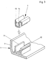
- the radiator grille 1 is fastened in the region of its lower edge with the aid of the fastening elements 4, which according to the exemplary embodiment each consist of a first latching and holding device 15 and a second latching and holding device 16. Both locking and holding devices 15 and 16 act like clips, so that the fastening element 4 is a multiple snap element.
- One or the first latching and holding device 15 is arranged directly and expediently in one piece on the rear side 5 of the radiator grille 1. It also serves as a carrier for the second locking and holding device 16.
- the second latching and holding device 16 is movably arranged on the first latching and holding device 15. In the chosen design, this is expedient for manufacturing reasons and for reasons of assembly.
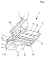
- the first latching and holding device 15 which is cut off in FIG. 4 and shown in perspective, comprises two arms 17 projecting from the rear side 5 of the part 1 to be fastened, a guide 18 and holding means 19 for the second latching and holding device 16 It also has a pivotable support element 20, which faces a back surface 5 of the rear side 5 of the part 1 to be fastened.
- a toothing serves as a holding means 19 and is arranged on the underside of the arms 17.
- the arms 17 are also connected to one another via a web 22.
- the support element 2o is wedge-shaped in cross section and at the same time provided with the guide 18 for the second latching and holding device 16.
- the wedge-shaped support element 2o is also movable relative to the two arms 17.
- the support element 2o can be pivoted about the web 22 serving as an axis such that the contact surface 21 at the free end 23 of the support element 2o can be moved approximately parallel to the rear side 5 of the part 1 or the radiator grille 1.
- the second locking and holding device 16 belonging to the fastening element 4 is a separately producible part (FIG. 5), which has a central piece 24, a guide element 25 connected to it, fastening means 26 for fixing to the arms 17 of the first locking and holding element 15 and locking projections 27 and support and holding elements 28 or 29 has.
- the support elements 28 are spacers and the holding elements 29 are hook parts.
- the support and holding elements 28, 29 are arranged on side parts 3o, 31, which extend essentially parallel to the center piece 24 and have guide elements 32, 33, with the aid of which the locking and holding device 16 on the arms 17 of the first locking and holding device 15 can be plugged on.
- the side parts 3o and 31 also each have a toothing serving as fastening means 26 on the arms 17, so that the latching and holding device 16 can be securely and immovably fixed to the first latching and holding device 15 in its fastening position.
- the middle piece 24 of the locking and holding device 16 is provided with a transversely extending film hinge 34 and has a spring element 35 at its end facing away from the guide elements 32, 33, which serves as a carrier for the guide element 25 and the locking projections 27.
- the latching and holding device 16 is first arranged or fixed in the guide 18 of the first latching and holding device with the aid of the guide element 25 and then pushed so far with its guide elements 32, 33 onto the arms 17 of the latching and holding device 15 , until the holding means 19 designed as cooperating teeth on the underside of the arms 17 and the fastening means 26 designed as corresponding teeth on the top of the side parts 30, 31 of the second latching and holding device 16 are sufficient Ensure secure connection and attachment to each other.
- FIGs 7a and 8a the latching and holding device 16 is arranged on the arms 17, but it is not yet there in its final position for fastening the part 1 according to FIG. 7c or FIG. 8c.
- the locking projections 27 and the spring element 35 of the second locking and holding device 16 are assigned at least one holding projection 36 on the rear side 5 of the part 1 to be fastened, as shown in FIGS. 2, 4 and 6 and also 7 and 8.
- This holding projection 36 is expediently formed in one piece on the rear side 5 of the part 1 to be fastened.
- the function and operation of the fastener 4 is as follows.
- the part 1 to be fastened is pushed with its upper edge parts 9 in the plug-in elements 7 located there over the upper edge 8 or mounting flange 8 of the mounting opening 2, as is already shown in FIG. 2.
- the lower edge parts 1o of the part 1 to be fastened are still at a certain distance from the assembly opening 2. This can be seen from the illustrations in FIGS. 7a and 8a. If the part 1 to be fastened is now pressed with its lower edge parts 1o onto the lower edge 6 or the mounting edge 6 of the mounting opening 2, the slope 37 facing the free edge 6 first hits the underside of the support element 2o of the first latching and holding device 15 on this free edge 6 and causes the support element 2o to be pivoted upward about the web 22 (FIG. 4), the parts which are seen from the film hinge 34 also being pivoted upward by the second latching and holding device 15 extend to the rear 5 of the part 1 to be fastened. These include the spring element 35 and the holding projections 36 arranged there.
- the latching projections 27 are directly at the same height as the retaining projection 36 on the rear side 5 of the part 1.
- the hook parts 29 lie on the second 8b on the outside at the edge 6 of the assembly opening 2.
- the support element 2o slides with its contact surface 21 behind the edge 6 of the assembly opening 2 and at the same time the hook parts 29 pull the second catch and holding device 16 still further on the arms 17 of the first latching and holding device 15.
- the arms 17 penetrate even further into the guide elements 32, 33, so that finally the spacers 28 (FIG. 8c) also rest on the rear side 5 of the part 1 to be fastened.
- the part 1 to be fastened is, as shown in FIGS. 2 and 7c and 8c, in the region of the lower edge parts 10 on the rear side 5 or on the inside of the Assembly opening 2 is held on the support element 2o of the first latching and holding device 15 with the aid of the contact surface 21 and fixed on the second latching and holding device 16 with the aid of the hook parts 29. Furthermore, the spring-elastic spacers 28 serve as additional vibration protection against rattling when vibrations should occur.
- the latching projection (s) 27 also supports the part 1 to be fastened by abutment on the retaining projection 36 which is arranged on the rear side 1 of the part 1.
- the latching and holding devices 15, 16 are thus effective both in opposite directions and in directions perpendicular to one another and therefore guarantee rattle-free attachment even in the event of vibrations.
Abstract
Description
Die Erfindung betrifft eine Vorrichtung zum Befestigen von Teilen und insbesondere von Kraftfahrzeugteilen in Montageöffnungen wie z.B. von Kühlergittern in den zugehörigen Öffnungen der Motorhauben.The invention relates to a device for fastening parts and in particular motor vehicle parts in assembly openings such as of radiator grilles in the corresponding hood openings.
Die Befestigung der Kühlergitter in ihren Öffnungen in den Motorhauben erfolgt mit Hilfe von Schrauben. Auch wenn hierzu selbstschneidende Schrauben verwendet werden, ist der Arbeitsaufwand jeweils groß und mühsam, weil die Befestigung in Form einer Über-Kopf-Montage erfolgen muß.The radiator grille is fastened in its openings in the bonnet using screws. Even if self-tapping screws are used for this purpose, the work involved is large and tedious because the attachment must be in the form of an overhead installation.
Der Erfindung liegt daher die Aufgabe zugrunde, eine Vorrichtung zum Befestigen von Teilen wie insbesondere von Kraftfahrzeugteilen in ihren Montageöffnungen vorzusehen, wobei die Befestigung nicht mit Hilfe von Schrauben erfolgt, sondern auf einfachere und weniger mühsame Art und Weise.The invention is therefore based on the object of providing a device for fastening parts, in particular motor vehicle parts, in their assembly openings, the fastening not being carried out with the aid of screws, but in a simpler and less tedious manner Wise.
Zur Lösung dieser Aufgabe sieht die Erfindung vor, daß mindestens ein clipsartiges Befestigungselement auf der Rückseite des zu befestigenden Teiles angeordnet ist und daß dieses Befestigungselement mindestens ein Stütz- und Halteteil aufweist, das neben dem Rand der Montageöffnung angreift.To achieve this object, the invention provides that at least one clip-like fastener is arranged on the back of the part to be fastened and that this fastener has at least one support and holding part which engages next to the edge of the mounting opening.
Durch die Verwendung des clipsartigen Befestigungselementes ist es möglich, das zu befestigende Teil in die Montageöffnung einzusetzen und dort zu verankern, ohne daß zusätzlich noch irgendwelche Maßnahmen erforderlich sind. Das clipsartige Befestigungselement erleichtert daher die Montage, wobei dies sowohl für den körperlichen Aufwand als auch für den Zeitbedarf gilt.By using the clip-like fastening element, it is possible to insert the part to be fastened into the assembly opening and to anchor it there without any additional measures being required. The clip-like fastening element therefore facilitates assembly, this being true both for the physical effort and for the time required.
In Weiterbildung der Erfindung ist das clipsartige Befestigungselement ein Mehrfachschnappelement. Es umfasst getrennt wirksame und gemeinsam in ihre Rast- und Halteposition bewegbare Stütz- und Halteteile, die clipsartig mit dem Rand der Montageöffnung verrasten. Dies erfolgt auch mit unterschiedlichen Wirkrichtungen, so daß eine Befestigung sowohl in einer Hauptwirkrichtung als auch senkrecht dazu möglich ist.In a further development of the invention, the clip-like fastening element is a multiple snap element. It comprises separately effective supporting and holding parts which can be moved together into their latching and holding position and which latch in a clip-like manner with the edge of the assembly opening. This is also done with different directions of action, so that attachment is possible both in a main direction of action and perpendicular to it.
Ein bevorzugtes Anwendungsgebiet für das erfindungsgemäße Befestigungselement ist der Einbau des Kühlergitters in seine Montageöffnung in der Motorhaube eines Kraftfahrzeuges. Hier genügt es zur Montage, wenn das Kühlergitter mit seinem Umfang teilweise auf den oberen Rand der Öffnung in der Motorhaube geschoben und sodann mit Hilfe des bzw. der unten am Kühlergitter befindlichen Befestigungselemente im unteren Bereich der Öffnung der Motorhaube durch Einclipsen verankert wird. Das Kühlergitter ist somit von vorne in die Öffnung einsetzbar und befestigbar, ohne daß irgendwelche weiteren Maßnahmen ergriffen werden müssen. Auch wird hierbei eine diebstahlsichere Verankerung erzielt.A preferred area of application for the fastening element according to the invention is the installation of the radiator grille in its mounting opening in the hood of a motor vehicle. Here it is sufficient for assembly if the circumference of the radiator grille is partially pushed onto the upper edge of the opening in the bonnet and then with the aid of the fastening element (s) located at the bottom of the radiator grille is anchored in the lower area of the hood opening by clipping. The radiator grille can thus be inserted and fastened from the front into the opening without any further measures having to be taken. Theft-proof anchoring is also achieved here.
Weitere Merkmale der Erfindung gehen aus Unteransprüchen im Zusammenhang mit der Zeichnung und der Beschreibung hervor.Further features of the invention emerge from subclaims in connection with the drawing and the description.
Die Erfindung wird nachstehend anhand eines Ausführungsbeispieles, das in der Zeichnung dargestellt ist, näher beschrieben. Dabei zeigen:
- Fig. 1:
- eine zum Teil abgeschnitte Ansicht eines in eine Montageöffnung eingesetzten Teiles bzw. konkret eine Ansicht eines Kühlergitters und einer abgeschnittenen Motorhaube eines Kraftfahrzeuges;
- Fig. 2:
- einen Schnitt längs der Linie II-II in Fig. 1 in größerem Maßstab;
- Fig. 3:
- in nochmals größerem Maßstab sowie im Schnitt und in perspektivischer Ansicht eine Einzelheit aus Fig. 2;
- Fig. 4:
- im Schnitt sowie in perspektivischer Darstellung ein Stück des unteren Randes des zu befestigenden Teiles zusammen mit Teilen des Befestigungselementes;
- Fig. 5:
- in perspektivischer Darstellung eine Ansicht eines Rast- und Halteelementes des Befestigungselementes;
- Fig. 6:
- einen Schnitt längs der Linie VI-VI in Fig. 2;
- Fig. 7:
- einen Schnitt längs der Linie VII-VII in Fig. 6 mit der Darstellung von drei Positionen a ( ), b ( ) und c ( ) während der Montage;
- Fig. 8:
- einen Schnitt längs der Linie VIII-VIII in Fig. 6 mit der Darstellung mehrerer Positionen a, b und c während der Montage und
- Fig. 9:
- abgeschnitten sowie in größerem Maßstab eine perspektivische Darstellung eines Hakenteiles und eines Abstandshalters an der einen Rast- und Halteeinrichtung.
- Fig. 1:
- a partially cut-away view of a part inserted into an assembly opening or specifically a view of a radiator grille and a cut-off bonnet of a motor vehicle;
- Fig. 2:
- a section along the line II-II in Figure 1 on a larger scale.
- Fig. 3:
- on a still larger scale and in section and in perspective view a detail from Fig. 2;
- Fig. 4:
- in section and in perspective a piece of the lower edge of the part to be fastened together with parts of the fastener;
- Fig. 5:
- a perspective view of a locking and holding element of the fastener;
- Fig. 6:
- a section along the line VI-VI in Fig. 2;
- Fig. 7:
- a section along the line VII-VII in Figure 6 showing three positions a (), b () and c () during assembly.
- Fig. 8:
- a section along the line VIII-VIII in Fig. 6 showing a plurality of positions a, b and c during assembly and
- Fig. 9:
- cut off and on a larger scale a perspective view of a hook part and a spacer on the one locking and holding device.
Eine Vorrichtung zum Befestigen eines Teiles 1 wie beispielsweise eines Kraftfahrzeugteiles bzw. gemäß Ausführungsbeispiel eines Kühlergitters 1 in einer Montageöffnung 2 einer Motorhaube 3 umfasst clipsartige Befestigungselemente 4, die an der Rückseite 5 des jeweils zu befestigenden Teiles 1 angeordnet sind. Wie aus der Darstellung in Fig. 1 hervorgeht, befinden sich drei Befestigungselemente 4 im unteren Bereich der Rückseite 5 des Kühlergitters 1 und wirken dort mit der Montageöffnung 2 der Motorhaube 3 zusammen. Ferner umfasst die Vorrichtung zum Befestigen des Kühlergitters 1 auch Steckelemente 7, die im oberen Bereich des Kühlergitters 1 angeordnet sind und dort mit dem oberen Rand 8 der Montageöffnung 2 zusammenwirken. Sowohl der untere Rand 6 als auch der obere Rand 8 der Montageöffnung 2 sind schmale, flanschartige sowie gebördelte Blechteile (Fig. 2).A device for fastening a
Das gemäß Ausführungsbeispiel konkret in der Montageöffnung 2 zu befestigende Kühlergitter 1 weist obere Randteile 9 und untere Randteile 1o auf. Zu den oberen Randteilen 9 gehören auch Halterippen 11, 12, die zur Fixierung der Steckelemente 7 dienen. Mit Hilfe dieser Steckelemente 7 wird das Kühlergitter 1 mit dem oberen Rand 8 bzw. Montageflansch 8 der Montageöffnung 2 verbunden, wozu das Kühlergitter 1 lediglich auf diesen Montageflansch 8 von unten nach oben aufgeschoben wird. Vorsprünge 13 und 14 und eine entsprechend enge Tolerierung sowie eine geeignete Werkstoffauswahl stellen sicher, daß das bzw. die Steckelemente das Kühlergitter 1 im oberen Randbereich sicher und rüttelfrei mit dem Montageflansch bzw. oberen Rand 8 der Montageöffnung 2 verbinden.The
Die Befestigung des Kühlergitters 1 im Bereich seines unteren Randes erfolgt mit Hilfe der Befestigungselemente 4 , die gemäß Ausführungsbeispiel jeweils aus einer ersten Rast- und Halteeinrichtung 15 und einer zweiten Rast- und Halteeinrichtung 16 bestehen. Beide Rast- und Halteeinrichtungen 15 und 16 wirken clipsartig, so daß das Befestigungselement 4 ein Mehrfachschnappelement ist.The
Die eine bzw. erste Rast- und Halteeinrichtung 15 ist unmittelbar und zweckmäßigerweise einstückig an der Rückseite 5 des Kühlergitters 1 angeordnet. Sie dient zugleich als Träger für die zweite Rast- und Halteeinrichtung 16.One or the first latching and
Die zweite Rast- und Halteeinrichtung 16 ist auf der ersten Rast- und Halteeinrichtung 15 bewegbar angeordnet. Dies ist bei der gewählten Konstruktion aus fertigungstechnischen Gründen und aus Montagegründen zweckmäßig.The second latching and holding
Die erste Rast- und Halteeinrichtung 15, die in Fig. 4 abgeschnitten sowie in perspektivischer Darstellung wiedergegeben ist, umfasst zwei von der Rückseite 5 des zu befestigenden Teiles 1 wegragende Arme 17, eine Führung 18 sowie Haltemittel 19 für die zweite Rast- und Halteeinrichtung 16. Sie weist ferner ein ausschwenkbar angeordnetes Stützelement 2o auf, das mit einer Anlagefläche 21 der Rückseite 5 des zu befestigenden Teiles 1 zugewandt ist. Eine Verzahnung dient als Haltemittel 19 und ist jeweils an der Unterseite der Arme 17 angeordnet. Die Arme 17 sind ferner über einen Steg 22 miteinander verbunden. Das Stützelement 2o ist im Querschnitt keilförmig und zugleich mit der Führung 18 für die zweite Rast- und Halteeinrichtung 16 versehen. Das keilförmige Stützelement 2o ist ferner relativ zu den beiden Armen 17 bewegbar. Dazu ist das Stützelement 2o etwa um den als Achse dienenden Steg 22 derart verschwenkbar, daß die Anlagefläche 21 am freien Ende 23 des Stützelements 2o annähernd parallel zur Rückseite 5 des Teiles 1 bzw. Kühlergitters 1 bewegbar ist.The first latching and holding
Die zweite, zu dem Befestigungselement 4 gehörende Rast- und Halteeinrichtung 16 ist ein getrennt herstellbares Teil (Fig. 5), das ein Mittelstück 24, ein mit diesem verbundenes Führungselement 25, Befestigungsmittel 26 zum Fixieren an den Armen 17 des ersten Rast- und Halteelementes 15 und Rastvorsprünge 27 sowie Stütz- und Halteelemente 28 bzw. 29 aufweist. Die Stützelemente 28 sind Abstandshalter und die Haltelemente 29 sind Hakenteile.The second locking and holding
Die Stütz- und Halteelemente 28, 29 sind an Seitenteilen 3o, 31 angeordnet, die sich im wesentlichen parallel zu dem Mittelstück 24 erstrecken und Führungselemente 32, 33 aufweisen, mit deren Hilfe die Rast- und Halteeinrichtung 16 auf die Arme 17 der ersten Rast- und Halteeinrichtung 15 aufsteckbar ist. Die Seitenteile 3o und 31 weisen ferner ebenfalls je eine als Befestigungsmittel 26 an den Armen 17 dienende Verzahnung auf, so daß die Rast- und Halteeinrichtung 16 in ihrer zur Befestigung dienenden Position sicher und unverrückbar an der ersten Rast- und Halteeinrichtung 15 fixierbar ist.The support and holding
Das Mittelstück 24 der Rast- und Halteeinrichtung 16 ist mit einem sich quer erstreckenden Filmscharnier 34 versehen und weist an ihrem den Führungselementen 32, 33 abgewandten Ende ein Federelement 35 auf, das als Träger für das Führungselement 25 und die Rastvorsprünge 27 dient.The
Beim Zusammenbau wird die Rast- und Halteeinrichtung 16 zunächst mit Hilfe des Führungselementes 25 in der Führung 18 der ersten Rast- und Halteeinrichtung angeordnet bzw. fixiert und sodann mit seinen Führungselementen 32, 33 auf die Arme 17 der Rast- und Halteeinrichtung 15 so weit aufgeschoben, bis die als zusammenwirkende Verzahnungen ausgebildeten Haltemittel 19 an der Unterseite der Arme 17 und die als entsprechende Verzahnung ausgebildeten Befestigungsmittel 26 auf der Oberseite der Seitenteile 3o, 31 der zweiten Rast- und Halteeinrichtung 16 eine ausreichend sichere Verbindung und Befestigung aneinander gewährleisten. Diese Situation ist in den Figuren 7a und 8a dargestellt. Die Rast- und Halteeinrichtung 16 ist gemäß diesen Figuren zwar auf den Armen 17 angeordnet, doch befindet sie sich dort noch nicht in ihrer endgültigen, zur Befestigung des Teiles 1 dienenden Position gemäß Fig. 7c bzw. Fig. 8c.During assembly, the latching and holding
Den Rastvorsprüngen 27 und dem Federelement 35 der zweiten Rast- und Halteeinrichtung 16 ist mindestens ein Haltevorsprung 36 an der Rückseite 5 des zu befestigenden Teiles 1 zugeordnet, wie die Fig. 2, 4 und 6 und auch 7 und 8 zeigen. Dieser Haltevorsprung 36 ist zweckmäßigerweise einstückig an der Rückseite 5 des zu befestigenden Teiles 1 ausgebildet.The locking
Die Funktion und Wirkungsweise des Befestigungselementes 4 ist wie folgt.The function and operation of the
Zunächst wird das zu befestigende Teil 1 mit seinen oberen Randteilen 9 in den dort befindlichen Steckelementen 7 über den oberen Rand 8 bzw. Montageflansch 8 der Montageöffnung 2 geschoben, wie dies bereits in Fig. 2 dargestellt ist. Dabei befinden sich die unteren Randteile 1o des zu befestigednen Teiles 1 noch in gewissem Abstand vor der Montageöffnung 2. Dies geht aus den Darstellungen in den Figuren 7a und 8a hervor. Wird jetzt das zu befestigende Teil 1 mit seinen unteren Randteilen 1o auf den unteren Rand 6 bzw. den Montagerand 6 der Montageöffnung 2 gedrückt, so trifft zunächst die dem freien Rand 6 zugewandte Schräge 37 an der Unterseite des Stützelementes 2o der ersten Rast- und Halteeinrichtung 15 auf diesen freien Rand 6 und bewirkt, daß das Stützelement 2o um den Steg 22 (Fig. 4)nach oben verschwenkt wird, wobei von der zweiten Rast- und Halteeinrichtung 15 zugleich auch diejenigen Teile nach oben verschwenkt werden, die sich von dem Filmscharnier 34 aus gesehen zur Rückseite 5 des zu befestigenden Teiles 1 hin erstrecken. Dazu gehören das Federelement 35 und der bzw. die dort angeordneten Haltevorsprünge 36.First, the
Wenn bei dem gemäß Fig. 7 b nach oben erfolgenden Verschwenken des Stützelementes 2o die höchste Lage erreicht ist, stehen die Rastvorsprünge 27 unmittelbar in gleicher Höhe wie der Haltevorsprung 36 an der Rückseite 5 des Teiles 1. Gleichzeitig legen sich die Hakenteile 29 an der zweiten Rast- und Halteeinrichtung 16 gemäß Fig. 8b aussen an den Rand 6 der Montageöffnung 2.If the highest position is reached when the support element 2o is pivoted upward according to FIG. 7b, the latching
Wird jetzt das zu befestigende Teil 1 mit seinem unteren Rand noch weiter in Richtung auf den Rand 6 der Montageöffnung 2 bewegt, so gleitet das Stützelement 2o mit seiner Anlagefläche 21 hinter den Rand 6 der Montageöffnung 2 und gleichzeitig ziehen die Haktenteile 29 die zweite Rast- und Halteeinrichtung 16 noch weiter auf die Arme 17 der ersten Rast- und Halteeinrichtung 15. Die Arme 17 dringen hierbei noch tiefer in die Führungselemente 32, 33 hinein, so daß schließlich auch die Abstandshalter 28 (Fig. 8c) zur Anlage auf der Rückseite 5 des zu befestigenden Teiles 1 gelangen.If the
Das zu befestigende Teile 1 ist gemäß der Darstellung in den Figuren 2 sowie 7c und 8c im Bereich der unteren Randteile 1o auf der Rückseite 5 bzw. auf der Innenseite der Montageöffnung 2 mit Hilfe der Anlagefläche 21 am Stützelement 2o der ersten Rast- und Halteeinrichtung 15 gehalten und mit Hilfe der Hakenteile 29 an der zweiten Rast- und Halteeinrichtung 16 fixiert. Ferner dienen die federelastischen Abstandshalter 28 als zusätzliche Rüttelsicherung gegen Klappern, wenn Erschütterungen auftreten sollten.The
Schließlich stützt in der in den Fig. 2 und 7c sowie 8c dargestellten Befestigungslage auch der bzw. die Rastvorsprünge 27 das zu befestigende Teil 1 durch Anlage an dem Haltevorsprung 36, der an der Rückseite 1 des Teiles 1 angeordnet ist. Die Rast- und Halteeinrichtungen 15, 16 sind somit sowohl in entgegengesetzten Richtungen als auch in senkrecht zueinander stehenden Richtungen wirksam und garantieren daher eine klapperfreie Befestigung auch bei Erschütterungen.Finally, in the fastening position shown in FIGS. 2 and 7c and 8c, the latching projection (s) 27 also supports the
Claims (21)
Applications Claiming Priority (2)
| Application Number | Priority Date | Filing Date | Title |
|---|---|---|---|
| DE4303370 | 1993-02-05 | ||
| DE4303370A DE4303370A1 (en) | 1993-02-05 | 1993-02-05 | Device for fastening parts, in particular motor vehicle parts |
Publications (2)
| Publication Number | Publication Date |
|---|---|
| EP0609534A1 true EP0609534A1 (en) | 1994-08-10 |
| EP0609534B1 EP0609534B1 (en) | 1996-03-20 |
Family
ID=6479746
Family Applications (1)
| Application Number | Title | Priority Date | Filing Date |
|---|---|---|---|
| EP93120284A Expired - Lifetime EP0609534B1 (en) | 1993-02-05 | 1993-12-16 | Device for fastening parts, especially parts of motor vehicles |
Country Status (3)
| Country | Link |
|---|---|
| EP (1) | EP0609534B1 (en) |
| DE (2) | DE4303370A1 (en) |
| ES (1) | ES2086180T3 (en) |
Cited By (5)
| Publication number | Priority date | Publication date | Assignee | Title |
|---|---|---|---|---|
| GB2301068A (en) * | 1995-05-23 | 1996-11-27 | Plastal Zcp Spa | Radiator grill for motor vehicles |
| DE19730269A1 (en) * | 1997-07-15 | 1999-01-21 | Hella Kg Hueck & Co | Arrangement for joining two vehicle parts |
| GB2373764A (en) * | 2001-03-30 | 2002-10-02 | Lotus Car | Vehicle grille secured by hook and loop fastening means |
| FR2948903A1 (en) * | 2009-08-04 | 2011-02-11 | Peugeot Citroen Automobiles Sa | Air inlet grille for use with radiator grille of vehicle, has slot that is extended along horizontal element, and guiding unit that guides part of support of radiator grille to interior of slot |
| DE10116283B4 (en) * | 2001-03-31 | 2014-09-11 | Volkswagen Ag | Arrangement for accurately fitting an attachment to a base member, in particular a radiator grille on a bumper fascia of a motor vehicle |
Families Citing this family (2)
| Publication number | Priority date | Publication date | Assignee | Title |
|---|---|---|---|---|
| DE102016102966A1 (en) * | 2016-02-19 | 2017-08-24 | Dr. Ing. H.C. F. Porsche Aktiengesellschaft | Arrangement of an air intake grille in a body lid of a motor vehicle |
| CN108454384B (en) * | 2018-04-23 | 2023-10-13 | 延锋彼欧汽车外饰系统有限公司 | Active air inlet grille device of automobile |
Citations (7)
| Publication number | Priority date | Publication date | Assignee | Title |
|---|---|---|---|---|
| GB2031506A (en) * | 1978-09-30 | 1980-04-23 | Toyoda Gosei Kk | Structure for attaching together two bodies |
| US4356601A (en) * | 1979-07-16 | 1982-11-02 | Nifco Inc. | Plastic fastener |
| US4379648A (en) * | 1980-01-21 | 1983-04-12 | Nissan Motor Co., Ltd. | Fixing structure for radiator grille |
| US4521050A (en) * | 1984-02-10 | 1985-06-04 | General Motors Corporation | Shroud top vent grille retaining means |
| JPS60174318A (en) * | 1984-02-18 | 1985-09-07 | Nissan Motor Co Ltd | Cowl-grille installation structure |
| EP0332846A1 (en) * | 1988-03-12 | 1989-09-20 | Adam Opel Aktiengesellschaft | Radiator grille for motor vehicles |
| DE4106158A1 (en) * | 1990-08-07 | 1992-02-13 | Suzuki Motor Co | FRONT PANEL MOUNTING DEVICE FOR MOTOR VEHICLES |
-
1993
- 1993-02-05 DE DE4303370A patent/DE4303370A1/en not_active Withdrawn
- 1993-12-16 DE DE59301963T patent/DE59301963D1/en not_active Expired - Fee Related
- 1993-12-16 ES ES93120284T patent/ES2086180T3/en not_active Expired - Lifetime
- 1993-12-16 EP EP93120284A patent/EP0609534B1/en not_active Expired - Lifetime
Patent Citations (7)
| Publication number | Priority date | Publication date | Assignee | Title |
|---|---|---|---|---|
| GB2031506A (en) * | 1978-09-30 | 1980-04-23 | Toyoda Gosei Kk | Structure for attaching together two bodies |
| US4356601A (en) * | 1979-07-16 | 1982-11-02 | Nifco Inc. | Plastic fastener |
| US4379648A (en) * | 1980-01-21 | 1983-04-12 | Nissan Motor Co., Ltd. | Fixing structure for radiator grille |
| US4521050A (en) * | 1984-02-10 | 1985-06-04 | General Motors Corporation | Shroud top vent grille retaining means |
| JPS60174318A (en) * | 1984-02-18 | 1985-09-07 | Nissan Motor Co Ltd | Cowl-grille installation structure |
| EP0332846A1 (en) * | 1988-03-12 | 1989-09-20 | Adam Opel Aktiengesellschaft | Radiator grille for motor vehicles |
| DE4106158A1 (en) * | 1990-08-07 | 1992-02-13 | Suzuki Motor Co | FRONT PANEL MOUNTING DEVICE FOR MOTOR VEHICLES |
Non-Patent Citations (1)
| Title |
|---|
| PATENT ABSTRACTS OF JAPAN vol. 10, no. 14 (M - 447)<2071> 21 January 1986 (1986-01-21) * |
Cited By (8)
| Publication number | Priority date | Publication date | Assignee | Title |
|---|---|---|---|---|
| GB2301068A (en) * | 1995-05-23 | 1996-11-27 | Plastal Zcp Spa | Radiator grill for motor vehicles |
| GB2301068B (en) * | 1995-05-23 | 1998-10-14 | Plastal Zcp Spa | Radiator grill for motor vehicles |
| DE19730269A1 (en) * | 1997-07-15 | 1999-01-21 | Hella Kg Hueck & Co | Arrangement for joining two vehicle parts |
| DE19730269C2 (en) * | 1997-07-15 | 2002-07-18 | Hella Kg Hueck & Co | Device for fastening a first part to a second part |
| GB2373764A (en) * | 2001-03-30 | 2002-10-02 | Lotus Car | Vehicle grille secured by hook and loop fastening means |
| GB2373764B (en) * | 2001-03-30 | 2003-04-23 | Lotus Car | An automobile with a novel grille arrangement |
| DE10116283B4 (en) * | 2001-03-31 | 2014-09-11 | Volkswagen Ag | Arrangement for accurately fitting an attachment to a base member, in particular a radiator grille on a bumper fascia of a motor vehicle |
| FR2948903A1 (en) * | 2009-08-04 | 2011-02-11 | Peugeot Citroen Automobiles Sa | Air inlet grille for use with radiator grille of vehicle, has slot that is extended along horizontal element, and guiding unit that guides part of support of radiator grille to interior of slot |
Also Published As
| Publication number | Publication date |
|---|---|
| EP0609534B1 (en) | 1996-03-20 |
| DE4303370A1 (en) | 1994-08-11 |
| DE59301963D1 (en) | 1996-04-25 |
| ES2086180T3 (en) | 1996-06-16 |
Similar Documents
| Publication | Publication Date | Title |
|---|---|---|
| DE69818489T2 (en) | SNAP FIXING | |
| DE102006041734B4 (en) | Device for fastening an airbag unit in an assembly of a motor vehicle, in particular in a steering wheel, by latching | |
| EP1383967B1 (en) | Cover for a drainage device | |
| DE19541180A1 (en) | Means for fastening an airbag module | |
| EP1792361B1 (en) | Fixing device for a motor vehicle antenna | |
| DE2931163A1 (en) | WHEEL COVER | |
| EP0691496A1 (en) | Expansion anchoring device | |
| EP0609534A1 (en) | Device for fastening parts, especially parts of motor vehicles | |
| DE60123349T2 (en) | fastening device | |
| DE102017004707A1 (en) | Bumper cover with detachable cover | |
| EP1610980A1 (en) | Device for fixing a housing, in particular of a motor-vehicle battery, to a support | |
| EP0983172B1 (en) | Wiper blade and replacement kit for a wiper blade | |
| DE102009033938B4 (en) | Roof window and method for fixing a cover plate | |
| EP3327240B1 (en) | Holding device for holding a sun protection device and holding system | |
| DE3026441C2 (en) | Adjustment device for sliding windows | |
| DE19510603A1 (en) | Vehicle seatbelt winder housing with interlocking tabs | |
| EP1769970B1 (en) | Attachment system | |
| WO2004113124A1 (en) | External rearview mirror for vehicles, preferably motor vehicles | |
| DE3330174C2 (en) | ||
| DE19734601A1 (en) | Perforated disc | |
| DE112019006152T5 (en) | SECURING DEVICE FOR VEHICLES | |
| DE19508143C2 (en) | Holding element with locking means | |
| EP3860400B1 (en) | Securing device for a panel of a drawer on a frame | |
| EP0189100B1 (en) | Component part with a tension member attached to it | |
| EP0389438B1 (en) | Snowguard |
Legal Events
| Date | Code | Title | Description |
|---|---|---|---|
| PUAI | Public reference made under article 153(3) epc to a published international application that has entered the european phase |
Free format text: ORIGINAL CODE: 0009012 |
|
| AK | Designated contracting states |
Kind code of ref document: A1 Designated state(s): DE ES FR GB IT SE |
|
| 17P | Request for examination filed |
Effective date: 19940811 |
|
| 17Q | First examination report despatched |
Effective date: 19940912 |
|
| GRAH | Despatch of communication of intention to grant a patent |
Free format text: ORIGINAL CODE: EPIDOS IGRA |
|
| GRAA | (expected) grant |
Free format text: ORIGINAL CODE: 0009210 |
|
| AK | Designated contracting states |
Kind code of ref document: B1 Designated state(s): DE ES FR GB IT SE |
|
| PG25 | Lapsed in a contracting state [announced via postgrant information from national office to epo] |
Ref country code: GB Effective date: 19960320 Ref country code: FR Effective date: 19960320 |
|
| REF | Corresponds to: |
Ref document number: 59301963 Country of ref document: DE Date of ref document: 19960425 |
|
| ITF | It: translation for a ep patent filed |
Owner name: STUDIO JAUMANN |
|
| REG | Reference to a national code |
Ref country code: ES Ref legal event code: FG2A Ref document number: 2086180 Country of ref document: ES Kind code of ref document: T3 |
|
| PG25 | Lapsed in a contracting state [announced via postgrant information from national office to epo] |
Ref country code: SE Effective date: 19960620 |
|
| EN | Fr: translation not filed | ||
| GBV | Gb: ep patent (uk) treated as always having been void in accordance with gb section 77(7)/1977 [no translation filed] |
Effective date: 19960320 |
|
| PGFP | Annual fee paid to national office [announced via postgrant information from national office to epo] |
Ref country code: DE Payment date: 19961104 Year of fee payment: 4 |
|
| PGFP | Annual fee paid to national office [announced via postgrant information from national office to epo] |
Ref country code: ES Payment date: 19961205 Year of fee payment: 4 |
|
| PLBE | No opposition filed within time limit |
Free format text: ORIGINAL CODE: 0009261 |
|
| STAA | Information on the status of an ep patent application or granted ep patent |
Free format text: STATUS: NO OPPOSITION FILED WITHIN TIME LIMIT |
|
| 26N | No opposition filed | ||
| PG25 | Lapsed in a contracting state [announced via postgrant information from national office to epo] |
Ref country code: DE Free format text: LAPSE BECAUSE OF NON-PAYMENT OF DUE FEES Effective date: 19980901 |
|
| PG25 | Lapsed in a contracting state [announced via postgrant information from national office to epo] |
Ref country code: ES Free format text: LAPSE BECAUSE OF NON-PAYMENT OF DUE FEES Effective date: 19981217 |
|
| REG | Reference to a national code |
Ref country code: ES Ref legal event code: FD2A Effective date: 19990114 |
|
| PG25 | Lapsed in a contracting state [announced via postgrant information from national office to epo] |
Ref country code: IT Free format text: LAPSE BECAUSE OF NON-PAYMENT OF DUE FEES;WARNING: LAPSES OF ITALIAN PATENTS WITH EFFECTIVE DATE BEFORE 2007 MAY HAVE OCCURRED AT ANY TIME BEFORE 2007. THE CORRECT EFFECTIVE DATE MAY BE DIFFERENT FROM THE ONE RECORDED. Effective date: 20051216 |