EP0609170A1 - Emergency egress illuminator and marker light strip - Google Patents
Emergency egress illuminator and marker light strip Download PDFInfo
- Publication number
- EP0609170A1 EP0609170A1 EP94630002A EP94630002A EP0609170A1 EP 0609170 A1 EP0609170 A1 EP 0609170A1 EP 94630002 A EP94630002 A EP 94630002A EP 94630002 A EP94630002 A EP 94630002A EP 0609170 A1 EP0609170 A1 EP 0609170A1
- Authority
- EP
- European Patent Office
- Prior art keywords
- passageway
- string
- emergency
- strip
- light
- Prior art date
- Legal status (The legal status is an assumption and is not a legal conclusion. Google has not performed a legal analysis and makes no representation as to the accuracy of the status listed.)
- Granted
Links
Images
Classifications
-
- G—PHYSICS
- G08—SIGNALLING
- G08B—SIGNALLING OR CALLING SYSTEMS; ORDER TELEGRAPHS; ALARM SYSTEMS
- G08B7/00—Signalling systems according to more than one of groups G08B3/00 - G08B6/00; Personal calling systems according to more than one of groups G08B3/00 - G08B6/00
- G08B7/06—Signalling systems according to more than one of groups G08B3/00 - G08B6/00; Personal calling systems according to more than one of groups G08B3/00 - G08B6/00 using electric transmission, e.g. involving audible and visible signalling through the use of sound and light sources
- G08B7/062—Signalling systems according to more than one of groups G08B3/00 - G08B6/00; Personal calling systems according to more than one of groups G08B3/00 - G08B6/00 using electric transmission, e.g. involving audible and visible signalling through the use of sound and light sources indicating emergency exits
-
- F—MECHANICAL ENGINEERING; LIGHTING; HEATING; WEAPONS; BLASTING
- F21—LIGHTING
- F21S—NON-PORTABLE LIGHTING DEVICES; SYSTEMS THEREOF; VEHICLE LIGHTING DEVICES SPECIALLY ADAPTED FOR VEHICLE EXTERIORS
- F21S2/00—Systems of lighting devices, not provided for in main groups F21S4/00 - F21S10/00 or F21S19/00, e.g. of modular construction
-
- F—MECHANICAL ENGINEERING; LIGHTING; HEATING; WEAPONS; BLASTING
- F21—LIGHTING
- F21S—NON-PORTABLE LIGHTING DEVICES; SYSTEMS THEREOF; VEHICLE LIGHTING DEVICES SPECIALLY ADAPTED FOR VEHICLE EXTERIORS
- F21S4/00—Lighting devices or systems using a string or strip of light sources
- F21S4/20—Lighting devices or systems using a string or strip of light sources with light sources held by or within elongate supports
-
- F—MECHANICAL ENGINEERING; LIGHTING; HEATING; WEAPONS; BLASTING
- F21—LIGHTING
- F21S—NON-PORTABLE LIGHTING DEVICES; SYSTEMS THEREOF; VEHICLE LIGHTING DEVICES SPECIALLY ADAPTED FOR VEHICLE EXTERIORS
- F21S8/00—Lighting devices intended for fixed installation
- F21S8/03—Lighting devices intended for fixed installation of surface-mounted type
- F21S8/033—Lighting devices intended for fixed installation of surface-mounted type the surface being a wall or like vertical structure, e.g. building facade
-
- G—PHYSICS
- G08—SIGNALLING
- G08B—SIGNALLING OR CALLING SYSTEMS; ORDER TELEGRAPHS; ALARM SYSTEMS
- G08B7/00—Signalling systems according to more than one of groups G08B3/00 - G08B6/00; Personal calling systems according to more than one of groups G08B3/00 - G08B6/00
- G08B7/06—Signalling systems according to more than one of groups G08B3/00 - G08B6/00; Personal calling systems according to more than one of groups G08B3/00 - G08B6/00 using electric transmission, e.g. involving audible and visible signalling through the use of sound and light sources
- G08B7/066—Signalling systems according to more than one of groups G08B3/00 - G08B6/00; Personal calling systems according to more than one of groups G08B3/00 - G08B6/00 using electric transmission, e.g. involving audible and visible signalling through the use of sound and light sources guiding along a path, e.g. evacuation path lighting strip
-
- F—MECHANICAL ENGINEERING; LIGHTING; HEATING; WEAPONS; BLASTING
- F21—LIGHTING
- F21W—INDEXING SCHEME ASSOCIATED WITH SUBCLASSES F21K, F21L, F21S and F21V, RELATING TO USES OR APPLICATIONS OF LIGHTING DEVICES OR SYSTEMS
- F21W2111/00—Use or application of lighting devices or systems for signalling, marking or indicating, not provided for in codes F21W2102/00 – F21W2107/00
- F21W2111/02—Use or application of lighting devices or systems for signalling, marking or indicating, not provided for in codes F21W2102/00 – F21W2107/00 for roads, paths or the like
-
- F—MECHANICAL ENGINEERING; LIGHTING; HEATING; WEAPONS; BLASTING
- F21—LIGHTING
- F21Y—INDEXING SCHEME ASSOCIATED WITH SUBCLASSES F21K, F21L, F21S and F21V, RELATING TO THE FORM OR THE KIND OF THE LIGHT SOURCES OR OF THE COLOUR OF THE LIGHT EMITTED
- F21Y2103/00—Elongate light sources, e.g. fluorescent tubes
- F21Y2103/10—Elongate light sources, e.g. fluorescent tubes comprising a linear array of point-like light-generating elements
-
- F—MECHANICAL ENGINEERING; LIGHTING; HEATING; WEAPONS; BLASTING
- F21—LIGHTING
- F21Y—INDEXING SCHEME ASSOCIATED WITH SUBCLASSES F21K, F21L, F21S and F21V, RELATING TO THE FORM OR THE KIND OF THE LIGHT SOURCES OR OF THE COLOUR OF THE LIGHT EMITTED
- F21Y2115/00—Light-generating elements of semiconductor light sources
- F21Y2115/10—Light-emitting diodes [LED]
-
- Y—GENERAL TAGGING OF NEW TECHNOLOGICAL DEVELOPMENTS; GENERAL TAGGING OF CROSS-SECTIONAL TECHNOLOGIES SPANNING OVER SEVERAL SECTIONS OF THE IPC; TECHNICAL SUBJECTS COVERED BY FORMER USPC CROSS-REFERENCE ART COLLECTIONS [XRACs] AND DIGESTS
- Y10—TECHNICAL SUBJECTS COVERED BY FORMER USPC
- Y10S—TECHNICAL SUBJECTS COVERED BY FORMER USPC CROSS-REFERENCE ART COLLECTIONS [XRACs] AND DIGESTS
- Y10S362/00—Illumination
- Y10S362/80—Light emitting diode
Landscapes
- Engineering & Computer Science (AREA)
- General Engineering & Computer Science (AREA)
- Physics & Mathematics (AREA)
- General Physics & Mathematics (AREA)
- Architecture (AREA)
- Business, Economics & Management (AREA)
- Emergency Management (AREA)
- Non-Portable Lighting Devices Or Systems Thereof (AREA)
Abstract
Description
- This invention relates generally to emergency lighting and, more particularly, to an emergency lighting aid for illuminating an emergency egress passageway in emergency clear air conditions and for guiding the egress of occupants along a path through the passageway during reduced visibility conditions.
- Many different types of lighting aids and systems have been devised and used to provide emergency lighting for use in buildings, aircraft and ships when conditions render normal ambient lighting insufficient for visibility. Such conditions include power outages, smoke caused by fires, water immersion, and chemical fog.
- One such system operable upon aircraft water immersion is disclosed in U.S. Patent No. 4,597,033 to Meggs et al and assigned to the assignee herein. This system utilizes light emitting diodes (L.E.D.s) to form a strip which illuminates the outline of an egress hatch in a helicopter when it is submerged in water and is effective in conditions of considerable turbidity.
- Another system, shown in U.S. Patent No. 4,682,147 to Bowman, utilizes a plurality of L.E.D.s in an "EXIT" sign. The sign is illuminated during power failure to indicate a means of egress to confined occupants.
- "EXIT" signs are a common sight in theaters, office buildings, stores, subways and other confining structures frequented by the public. Such signs are commonly illuminated by conventional incandescent light bulbs or, as illustrated in the Bowman patent, by L.E.D.s. The light sources in these signs emit their light spherically or hemispherically. Adequacy of these signs is frequently measured by their brightness, which is often equated to their visibility under emergency conditions.
- However, this brightness standard is now being questioned, since, under conditions of visibility impaired by the presence of smoke or fog, this brightness can become a handicap. This is caused by diffusion of the light by the particles comprising the smoke or fog. As the distance between the observer and the lighted sign increases, the distinctness of the letters, then the sign itself, rapidly diminishes until only a general glow is distinguishable.
- Also, as distance from the sign increases and as the light becomes scattered by the particulate matter, the source of the light becomes indistinguishable from the scattered light itself. Thus, the light source is no longer discernable at all. Unfortunately, a significant increase in light intensity increases the range of visibility only slightly. Thus, a very bright conventional sign becomes useless at a very short distance from it in dense smoke conditions which severely limit visibility.
- Light strips are now being provided along aisles of airplanes to mark an emergency egress route. These comprise spaced light sources that suffer the same general visibility problems as the signs, being subject to rapid light diffusion in smoke conditions. These light strips improve over signs, since they provide a light source that is closer to aircraft occupants by extending the length of the aisle.
- However, in dense smoke conditions, the lighted strip rapidly visually disappears as viewing distance increases and transitions through a series of glowing pinpoints of light until only one pinpoint is visible at a time. If only a single light pinpoint is discernable to an occupant, the location of the next pinpoint of light can only be guessed and the strip of light loses its primary function of marking a path to an emergency exit.
- The need for an emergency lighting system that better penetrates smoke and fog to provide a visible and discernable guide to occupant egress from a confined area during an emergency which is functional at distances much greater than prior lighting systems is disclosed in United State Patent No. 5,130,909 to Gross (the inventor herein) and assigned to the assignee herein. A floor-mounted strip of narrow cone angle L.E.D.s are axially aligned and have attached reflectors to direct their emitted light. Alternate L.E.D.s have their light directed in different directions to illuminate the floor in clear air emergency (normal lighting failure) conditions and provide a path marker in conditions of reduced visibility.
- However, this emergency lighting strip is most effective near the floor and to a crawling occupant and is less effective for an upright occupant. As such, it is a compromise attempt to provide both illumination and path marking. It requires central floor mounting to be most effective, although floor corner mounting is also described. In buildings, floor mounting is expensive, since it requires carpet cutting and/or floor modification.
- There is a need for an emergency lighting strip which marks an emergency egress path in conditions of reduced visibility for an upright escaping occupant.
- There is also a need for an emergency lighting strip which provides illumination at the center of an egress passageway during clear air emergency conditions for an escaping occupant.
- There is a further need for a single emergency lighting strip which functions to provide both illumination in emergency clear air conditions and path marking in reduced visibility emergency conditions for all escaping occupants.
- There is a yet further need for such an emergency lighting strip which is adaptable to a variety of different passageway configurations.
- It is an object of this invention to provide an emergency lighting strip which marks an emergency egress path in conditions of reduced visibility for an upright escaping occupant.
- It is another object of this invention to provide an emergency lighting strip which provides illumination at the center of an egress passageway during clear air emergency conditions for an escaping occupant.
- It is a further object of this invention to provide a single emergency lighting strip which functions to provide both illumination in emergency clear air conditions and path marking in reduced visibility emergency conditions for all escaping occupants.
- It is a yet further object of this invention to provide such an emergency lighting strip which is adaptable to a variety of different passageway configurations.
- In accordance with one aspect, this invention features an emergency egress lighting strip for illuminating an egress path in a passageway during conditions of reduced visibility which comprises an elongated transparent housing mounted on a passageway wall and an elongated string of narrow cone angle L.E.D.s mounted within the housing with their beam axes angled outwardly from the wall to provide a series of discrete beamed point sources of light to mark the path.
- In one embodiment, the path extends along the passageway leading to an exit portal, and the strip extends along the passageway wall leading to the portal, the L.E.D.s each having their beam axes angled upwardly from the horizontal.
- In another embodiment, the path extends through an exit portal in a wall of the passageway, the strip is provided on the wall framing the portal, and the L.E.D.s have their beam axes angled substantially perpendicular to the wall.
- In accordance with another aspect, this invention features an emergency egress lighting strip for illuminating a passageway during clear air conditions and for marking an egress path along the passageway during conditions of reduced visibility. The strip comprises an elongated transparent housing mounted on a passageway wall above the floor, and first and second strings of light emitting elements mounted within the housing, each being an intense point source of light which emit light along its beam axis at a narrow cone angle. The beam axes of the first string of elements are angled downward from the horizontal to illuminate a passageway, while the beam axes of the second string of elements are upward from the horizontal. The first string provides illumination at the center of the passageway floor of at least .2 lux under emergency clear air conditions, and the second string provides a series of beamed point sources of light which mark an egress path for said occupants along the passageway in conditions of reduced visibility.
- Preferably, the light emitting elements are L.E.D.s, each having a cone angle of not more than 45° and an intensity of at least .035 candela.
- In a further aspect, this invention features a housing having a part-circular cross-section and the strings of L.E.D.s are mounted on a bracket within the housing. This part-circular housing cross-section enables rotation of the L.E.D. mounting bracket within the housing to accommodate various mounting locations of the strip on the wall.
- Preferably, the mounting bracket includes a pair of legs arranged to mount the strings of L.E.D.s in a 90° L shape extending across each other; the second string L.E.D.s are spaced four inches apart and the first string L.E.D.s are spaced one-half inch apart, with an L.E.D. omitted at the location of each second string L.E.D.
- Preferably, the first string L.E.D.s provide illumination at the center of the floor of the passageway of at least 1 lux under emergency clear air conditions.
-
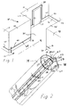
- Fig. 1 is a perspective view of a portion of a building incorporating one form of emergency lighting strip according to this invention;
- Fig. 2 is a partial perspective view of a portion of the emergency lighting strip of Fig. 1, sectioned to illustrate construction details;
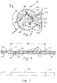
- Fig. 3 is an end view of the emergency lighting strip of Fig. 2, illustrating the relationship between the marker and illuminator strings of L.E.D.s;
- Fig. 4 is an elevation of the emergency lighting strip of Fig. 2, illustrating the spacing of the L.E.D.s in the illuminator string; and
- Fig. 5 is another elevation of the emergency lighting strip of Fig. 2, illustrating the spacing of the L.E.D.s in the marker string.
- Referring now to Fig. 1 of the drawings, a
structure 10, such as an office building, includes a passageway or hallway 12 that leads to an exterior-access exit door 14 in abuilding wall 16. Hallway 12 is defined byinterior walls floor 30. As illustrated here, the only access exteriorly ofbuilding 10 available to occupants is throughexit door 14. - Large structures, such as office buildings and hotels, often contain a "maze" of corridors and hallways that are easily traversed only by frequent occupants who have memorized their layout. Occasional occupants and visitors (or guests in the case of a hotel) can normally find their way only with the help of unlighted instructional signs. As mandated by local fire codes, illuminated "EXIT" signs usually are provided at ceiling level and at intervals to indicate an emergency egress path along a passageway, such as hallway 12. These signs are aesthetically undesirable (i.e have a high "ugly" index) and are expensive.
- During a clear emergency, normally accompanied by a power failure and consequent failure of normal building lighting, these normal "EXIT" signs are clearly visible if they are within sight. They also normally incorporate downward incandescent light which provides intermittent "islands" of illumination in the form of spaced pools of floor lighting. To assure constant visibility and better intermittent floor illumination in a building having a "maze" of hallways, a very large number of "EXIT" signs would be required, much to the aesthetic detriment of the building.
- These normal "EXIT" signs are actually of very limited, if any, utility in the case of a fire that generates significant smoke, as is the usual case. These illuminated signs rapidly become all but invisible at any appreciable distance. This occurs because the signs are usually backlit and thus emit light hemispherically. As the photons of this emitted light encounter the particulate matter comprising the smoke, they are randomly scattered and absorbed. Since the smoke is hot, it is densest near the ceiling where the signs are located and visibility of the signs quickly diminishes, as the smoke thickens. Also, all floor illumination is lost for the same reason.
- Thus, it is all too probable that building occupants would be unable to discern these "EXIT" signs and could wander aimlessly through the maze of unfamiliar hallways in search of an exit to escape from the building and its fire.
- As the smoke thickens, occupants are forced to move
nearer floor 30 where the smoke is least dense and where the supply of oxygen is greatest. This would, however, move the occupants even further from the overhead "EXIT" signs. To enhance the occupants' ability to quickly locate and utilize hallway 12 as an egress passageway along an emergency escape path to the exitportal door 14, in the case of fire or other emergency, this invention provides anemergency lighting strip 40. - Referring now to Figs. 2 and 3,
emergency lighting strip 40 comprises anassembly 42 of an illuminatingstring 44 of L.E.D.s 46 and amarker string 48 of L.E.D.s 50.Strings bracket 52 having an angular J shape and including L.E.D. mountinglegs strings - Marker L.E.D.s 50 in
string 48 project through apertures in alight barrier leg 58 of mountingbracket 52.Leg 58 serves to isolate the light fromilluminator string 44 so that it will not provide a background glow which would submerge the discrete beamed point sources of light produced by L.E.D.s 50 ofmarker string 48. - L.E.D.s 46 and 50 are all preferably green, have an output of at least .035 candela, and have a narrow cone angle, i.e. not larger than 45°. Larger L.E.D.s, such as those having an output of .12 candela and a cone angle of 24° can also be used. Those L.E.D.s having larger cone angles and smaller output function best as illuminators, while those with smaller cone angles function best as markers, penetrating smoke better. Different size L.E.D.s could be used on the same or on different strings, although this will complicate power supply.
- L.E.D.s 46 each include
electrical leads 46a and 46b which are attached toconductors 54a and 54b onbracket leg 54. Similarly, L.E.D.s 50 each haveelectrical leads 50a and 50b which attach toconductors 56a and 56b onbracket leg 56. Both strips of L.E.D.s are powered by a suitable emergency d.c. power supply, the size of which is dependent on how many and what power L.E.D.s are connected to it and to other environmental factors well known in the art of emergency illumination and power supply. - A strip of
wall molding 60 is attached to walls 18 - 28 at a point abovefloor 30. The elevation distance d (Fig. 1) above the floor is dependent on the illumination requirements, the width of the emergency egress passageway (here hallway 12), and L.E.D. size used in illuminatingstring 44. Aesthetically, it would be desirable to incorporatestrip 40 as the top portion of abaseboard 70 on the walls (Fig. 1). -
Wall molding 60 includes abase portion 62 and inwardly-angledside portions locking tangs bracket 52 is attached to anattachment strip 72 that is adhesively or otherwise attached tomolding base 62. After attachingattachment strip 72 tomolding 60, a transparentplastic housing 74, having a part-circular cross-section, is attached, via interengagement of itslocking tangs respective locking tangs - The part-circular shape of the cross-section of
housing 74 enables a common housing to be utilized regardless of the angular orientation of L.E.D.strings Housing 74 can be of any transparent material. - Figs. 4 and 5 illustrate the close spacing of the L.E.D.s in illuminating
string 44, preferably one-half inch, which provides the desired floor illumination. Every eighth illuminator L.E.D. 46 is missing to provide space for a marker L.E.D. 50. Fig. 4 shows the wide spacing A, preferably four inches, of the L.E.D.s inmarker string 48. This wide spacing provides discrete beamed point sources of light which are more distinct and, thus, more readily discernible by observers in heavy smoke, or other conditions of reduced visibility, than would be the case with more closely spaced L.E.D.s. This spacing reduces the amount of light scatter around each L.E.D. which tends to submerge each discrete beamed point source of light into the background light "noise". - While it is preferable to mount both the
marker string 48 of L.E.D.s 50 and theilluminator string 44 of L.E.D.s 46 withinhousing 74, either string may be used separately. For example, Fig. 1 shows an inverted U-shaped marker strip of L.E.D.s 80 mounted onwall 16 framingexit door 14. This strip preferably contains only a single string of L.E.D.s spaced one-half inch apart and mounted with their beam axes perpendicular towall 16. Thisstrip 80 provides a very bright marker forexit door 14. Sincestrip 80 does not mark a path along hallway 12, the distinctness of the individual L.E.D.s is not needed. - Of course, if only a marker emergency light strip is desired,
marker string 48 may be mounted alone inhousing 74 extending along hallway 12. Similarly, if only clear emergency illumination is required,illuminator string 44 may be mounted alone inhousing 74 to illuminatehallway floor 30. Again, because of the circularity ofhousing 74, these single strings may be oriented in any angular position. Thus, the mounting bracket, molding, housing and attachment strip are common to any marker, illuminator or combination application of the emergency lighting strip. - As stated above, the choice of mounting height, beam axis angles and L.E.D.size are dependent on environmental considerations. These factors are combined to provide an emergency lighting strip which meets mandated illumination requirements at the middle of
floor 30 in hallway 12 (centerline in Fig. 1). Currently, British requirements are .2 lux, although developing European requirements recite an illumination at passageway floor middle of 1 lux. - Applicant has conducted preliminary human observation testing with a 6-foot strip of lighting strip as described above, utilizing the .035 candela L.E.D.s at the indicated spacing, with the strip mounted at an above-floor height of about ten inches (150 mm). In clear air conditions and at a power of about 13 mA per L.E.D., illumination of the passageway floor exceeded .2 lux to a distance of about three feet (900 mm). Thus this strip would meet British requirements in a six-foot wide hallway.
- In testing in various visibility conditions in simulated smoke (from mild to dense), the marker L.E.D.s were observed by two upright observers. At 27% visibility (clear air = 100%), the marker string was discernible to two observers at a distance of 1.75 m by one and at 2.2 m by the other. This illustrates that, in a six-foot hallway, the emergency lighting strip is able to mark an escape path for an upright observer walking in the middle of the hallway in dense smoke conditions.
- Thus, an emergency lighting strip according to this invention provides an emergency lighting strip which marks an emergency egress path in conditions of reduced visibility for an upright escaping occupant. It also provides an emergency lighting strip which provides illumination at the center of an egress passageway during clear air emergency conditions for an escaping occupant. Further, it provides a single emergency lighting strip which functions to provide both illumination in emergency clear air conditions and path marking in reduced visibility emergency conditions for all escaping occupants. Yet further, it provides an emergency lighting strip which is adaptable to a variety of different passageway configurations.
- While only a preferred embodiment has been illustrated and described, obvious modifications are contemplated within the scope of this invention and the following claims. For example,
emergency lighting strip 40 could be mounted in ship passageways, aircraft cabins, train hallways, bus cabins, or in any other large environment whose occupants cannot easily identify an emergency escape path in clear air or, especially, in conditions of limited visibility. The strings of L.E.D.s could have their L.E.D.s differently spaced or unequally spaced. The strings could incorporate different size L.E.D.s, which could alter spacing. The angle between the beam axes of the two strings could be other than as illustrated. It is only necessary to have L.E.D.s or other light sources having narrow cone angles and sufficient power to be visible in conditions of reduced visibility and to illuminate the middle of a corridor floor in clear air.
Claims (10)
- An emergency egress lighting strip (40) for illuminating a passageway (12) during clear air conditions and for marking an egress path along the passageway (12) during conditions of reduced visibility, characterized by
an elongated transparent housing (74) mounted on a passageway (20) wall above the floor (30),
a first string (44) of light emitting elements (46) mounted within the housing (74), each being an intense point source of light which emit light along its beam axis (X) at a narrow cone angle, the axes (X) of the elements (46) being angled downward from the horizontal to illuminate the passageway (12), whereby
the first string (44) provides illumination at the center of the passageway floor (12) of at least .2 lux under emergency clear air conditions. - The lighting strip (40) of claim 1, further characterized in that the light emitting elements (46) are L.E.D.s, and that the light projected by the L.E.D.s (46) of the string (46) provides illumination at the center of the passageway floor (30) of at least 1 lux under emergency clear air conditions.
- The emergency egress lighting strip (40) of claim 1, further characterized by a second string (48) of light emitting elements (50) mounted within the housing (74), each being an intense point source of light which emit light along its beam axis (Y) at a narrow cone angle, the axes (Y) of the elements (50) being angled upward from the horizontal, whereby
the second string (48) provides a series of discrete point sources of light to mark an egress path for said occupants along the passageway (12) in conditions of reduced visibility. - The lighting strip (40) of claim 3, further characterized in that the light emitting elements (46, 50) are L.E.D.s, each having an axial intensity of at least .035 candela and a full cone angle no greater than 45 degrees.
- The lighting strip (40) of claim 3, further characterized in that the L.E.D.s (46) of the first string (44) are spaced at least one-half inch apart along the strip (40), and the L.E.D.s (50) of the second string (48) are spaced at least four inches along the strip (40).
- The lighting strip (40) of claim 3, further characterized in that the transparent housing (74) has a part-circular cross-section, and the strings (44, 48) of L.E.D.s are mounted on a bracket (52) within the housing (74), said part-circular housing cross-section enabling the use of a variety of different L.E.D. mounting brackets within the housing to provide a variety of different angular positions of the string of L.E.D.s to accommodate various mounting locations of the strip (40) on the wall (20) while utilizing a common housing (74).
- The lighting strip (40) of claim 6, further characterized in that the mounting bracket (52) includes a pair of legs (54, 56) arranged to mount the strings (44, 48) of L.E.D.s in an L shape extending across each other, the first string (44) omitting an L.E.D. (46) at the location of each second string L.E.D. (50).
- The lighting strip (40) of claim 7, further characterized in that L.E.D.s (50) of the second string (48) provide illumination at the center () of the floor (30) of the passageway (12) of at least 1 lux under emergency clear air conditions.

- The lighting strip(40) of claim 8, further characterized in that the mounting bracket legs (54, 56) are angled at 90° to each other, and the L.E.D.s (46, 50) each have an axial intensity of at least .035 candela and have a full cone angle no greater than 45 degrees.
- An emergency egress lighting strip (40) for illuminating a passageway (12) during clear air emergency conditions and for marking an egress path along the passageway (12) during emergency conditions of reduced visibility, characterized by
an elongated transparent housing (74) mounted on a passageway (20) wall above the floor (30),
a string (44, 48) of light emitting elements (48, 50) mounted within the housing (74), each being an intense point source of light which emit light along its beam axis (X, Y) at a narrow cone angle, the axes (X, Y) of the elements (50) extending outwardly of the wall to provide a series of spaced discrete point sources of light to mark an egress path for said occupants along the passageway (12) during said emergency conditions.
Applications Claiming Priority (2)
| Application Number | Priority Date | Filing Date | Title |
|---|---|---|---|
| US984707 | 1993-01-28 | ||
| US07/984,707 US5343375A (en) | 1993-01-28 | 1993-01-28 | Emergency egress illuminator and marker light strip |
Publications (2)
| Publication Number | Publication Date |
|---|---|
| EP0609170A1 true EP0609170A1 (en) | 1994-08-03 |
| EP0609170B1 EP0609170B1 (en) | 1996-11-06 |
Family
ID=25530788
Family Applications (1)
| Application Number | Title | Priority Date | Filing Date |
|---|---|---|---|
| EP94630002A Expired - Lifetime EP0609170B1 (en) | 1993-01-28 | 1994-01-27 | Emergency egress illuminator and marker light strip |
Country Status (3)
| Country | Link |
|---|---|
| US (1) | US5343375A (en) |
| EP (1) | EP0609170B1 (en) |
| DE (2) | DE69400826T2 (en) |
Cited By (8)
| Publication number | Priority date | Publication date | Assignee | Title |
|---|---|---|---|---|
| WO1998017351A1 (en) * | 1996-10-23 | 1998-04-30 | Wolfram Klingsch | Escape route signalling system |
| US6231205B1 (en) * | 1998-10-23 | 2001-05-15 | Powerwall, Inc. | Illuminated shelving |
| EP1133657A1 (en) * | 1998-11-24 | 2001-09-19 | LumiLeds Lighting U.S., LLC | Housing and mounting system for a strip lighting device |
| EP1231432A3 (en) * | 2001-02-12 | 2005-12-28 | Holger Schmidt | Accessory- and/or built-in profile |
| DE102005045782A1 (en) * | 2005-09-23 | 2007-03-29 | W & W Aufzug- und Industriekomponenten GmbH & Co. KG | Lamp to light up threshold of landing entrance shaft of lift has light diodes shedding light at different angles, housing fixed to door frame with bearer plate on which light diodes are fixed such as to direct light downwards |
| DE202013100307U1 (en) * | 2013-01-23 | 2014-04-29 | Hanning & Kahl Gmbh & Co. Kg | Emergency lighting for tunnels |
| WO2014174032A1 (en) * | 2013-04-26 | 2014-10-30 | Zumtobel Lighting Gmbh | Lighting assembly having an elongated lamp housing |
| EP2796781A3 (en) * | 1997-07-28 | 2015-05-27 | Philips Lumileds Lighting Company, LLC. | Strip lighting |
Families Citing this family (44)
| Publication number | Priority date | Publication date | Assignee | Title |
|---|---|---|---|---|
| US5688042A (en) * | 1995-11-17 | 1997-11-18 | Lumacell, Inc. | LED lamp |
| US6076936A (en) * | 1996-11-25 | 2000-06-20 | George; Ben | Tread area and step edge lighting system |
| US6183104B1 (en) | 1998-02-18 | 2001-02-06 | Dennis Ferrara | Decorative lighting system |
| US6210017B1 (en) * | 1999-05-28 | 2001-04-03 | Minolta Co., Ltd. | Self-emission road device for straight or curved road surface |
| US6283616B1 (en) | 1999-09-10 | 2001-09-04 | Aboolhassan Zoroufy | Corner mounted illuminator |
| US6788000B2 (en) * | 2000-05-12 | 2004-09-07 | E-Lite Technologies, Inc. | Distributed emergency lighting system having self-testing and diagnostic capabilities |
| DE20008713U1 (en) * | 2000-05-16 | 2000-09-14 | Reklame Conrad Wilden Nachf Gm | Illuminant |
| US6361186B1 (en) * | 2000-08-02 | 2002-03-26 | Lektron Industrial Supply, Inc. | Simulated neon light using led's |
| DE10106961A1 (en) * | 2001-02-15 | 2002-08-29 | Happich Fahrzeug & Ind Teile | Bleuchtungseinrichtung |
| WO2003019506A1 (en) * | 2001-08-31 | 2003-03-06 | Showers International Pty Ltd | Illuminated sign or display apparatus and mounting of circuit devices |
| US6896388B2 (en) * | 2002-04-03 | 2005-05-24 | E-Lite Technologies, Inc. | Path marking and lighting system |
| DE10311492B3 (en) * | 2003-03-15 | 2004-12-16 | Halemeier Gmbh & Co. Kg | Light has board at angle in rail, LEDs attached to one side that radiate light essentially normal to board, LEDs on other side that radiate essentially parallel to board, transversely to row of LEDs |
| US6976763B2 (en) * | 2003-04-25 | 2005-12-20 | Robbins Iii Edward S | Luminescent and fluorescent strip door highlights |
| US20050007778A1 (en) * | 2003-07-08 | 2005-01-13 | Jack Lin | Lamp structure for an electrical device |
| US6882111B2 (en) * | 2003-07-09 | 2005-04-19 | Tir Systems Ltd. | Strip lighting system incorporating light emitting devices |
| US7688222B2 (en) | 2003-09-18 | 2010-03-30 | Spot Devices, Inc. | Methods, systems and devices related to road mounted indicators for providing visual indications to approaching traffic |
| JP4939938B2 (en) * | 2004-04-23 | 2012-05-30 | 東芝モバイルディスプレイ株式会社 | Surface light source device and display device |
| US7255454B2 (en) * | 2004-06-24 | 2007-08-14 | Peterson John W | Emergency lighting system and method |
| WO2006039838A1 (en) * | 2004-10-12 | 2006-04-20 | Ben Fan | Simulated neon light |
| US7631985B1 (en) | 2005-05-02 | 2009-12-15 | Genlyte Thomas Group, Llc | Finite element and multi-distribution LED luminaire |
| US7511231B2 (en) * | 2005-07-15 | 2009-03-31 | Thomas & Betts International, Inc. | Illuminated recessed electrical floor box with transparent or translucent cover or window |
| US7572027B2 (en) * | 2005-09-15 | 2009-08-11 | Integrated Illumination Systems, Inc. | Interconnection arrangement having mortise and tenon connection features |
| US7635201B2 (en) * | 2006-08-28 | 2009-12-22 | Deng Jia H | Lamp bar having multiple LED light sources |
| US8013538B2 (en) * | 2007-01-26 | 2011-09-06 | Integrated Illumination Systems, Inc. | TRI-light |
| US20080204258A1 (en) * | 2007-02-12 | 2008-08-28 | Dayton Douglas C | Motion-, light-, and wireless-triggered lights and audio alarms |
| US7815341B2 (en) * | 2007-02-14 | 2010-10-19 | Permlight Products, Inc. | Strip illumination device |
| JP5019219B2 (en) * | 2007-09-26 | 2012-09-05 | Necエンベデッドプロダクツ株式会社 | Lighting device |
| US7905645B2 (en) * | 2007-11-15 | 2011-03-15 | Batti Stephen A | Illuminated floor mat |
| US8002426B2 (en) * | 2008-10-10 | 2011-08-23 | Tempo Industries, Inc. | Rail light |
| US8083367B2 (en) * | 2008-12-12 | 2011-12-27 | Anderson Jerry T | Emergency exit route illumination system and methods |
| WO2015048782A1 (en) * | 2013-09-30 | 2015-04-02 | Anderson Jerry T | Emergency exit route illumination system & methods |
| US20100271804A1 (en) * | 2009-04-22 | 2010-10-28 | Levine Jonathan E | Modular lighting device kit |
| US20120001554A1 (en) | 2010-06-30 | 2012-01-05 | Kevin Franklin Leadford | Linear light fixtures |
| US8939634B2 (en) * | 2010-06-30 | 2015-01-27 | Abl Ip Holding Llc | Egress lighting for two module luminaires |
| DE102010055704A1 (en) * | 2010-12-22 | 2012-06-28 | Airbus Operations Gmbh | System for evacuation of persons from a vehicle |
| US8388214B1 (en) | 2012-01-09 | 2013-03-05 | Azek Building Products, Inc. | Lighted railing and similar structures |
| DE202012101384U1 (en) * | 2012-04-16 | 2013-07-17 | Hanning & Kahl Gmbh & Co. Kg | Soil-integrated control system |
| US9062840B2 (en) * | 2012-05-24 | 2015-06-23 | Electrix, Llc | Cove lighting |
| US9889061B1 (en) | 2012-09-26 | 2018-02-13 | Lorelei Trask | Multi-function crutch and method of use |
| US10265230B2 (en) | 2014-11-26 | 2019-04-23 | Lorelei Trask | Exercise apparatus and method of use |
| US9903566B1 (en) | 2016-05-06 | 2018-02-27 | Darryl R. Johnston | Portable floor light |
| FI128383B (en) | 2017-06-22 | 2020-04-15 | Teknoware Oy | Lighting fixture and method for producing a lighting fixture |
| WO2019108582A1 (en) * | 2017-11-28 | 2019-06-06 | Contemporary Visions, LLC | Lighting system |
| US20200191358A1 (en) * | 2018-12-12 | 2020-06-18 | Aleddra Inc. | Elongated Lighting Apparatus |
Citations (3)
| Publication number | Priority date | Publication date | Assignee | Title |
|---|---|---|---|---|
| GB2215105A (en) * | 1988-02-16 | 1989-09-13 | Richard William Henry Ford | Personnel evacuation system |
| EP0352430A2 (en) * | 1988-07-26 | 1990-01-31 | Edwin Deser | Strip light fitting |
| US5130909A (en) * | 1991-04-18 | 1992-07-14 | Wickes Manufacturing Company | Emergency lighting strip |
Family Cites Families (7)
| Publication number | Priority date | Publication date | Assignee | Title |
|---|---|---|---|---|
| US4597033A (en) * | 1983-05-17 | 1986-06-24 | Gulf & Western Manufacturing Co. | Flexible elongated lighting system |
| US4600975A (en) * | 1984-01-25 | 1986-07-15 | Roberts James R | Architectural lighting apparatus |
| US4682147A (en) * | 1985-06-28 | 1987-07-21 | Don Gilbert Industries, Inc. | Emergency sign |
| US4884178A (en) * | 1989-03-13 | 1989-11-28 | Roberts James R | Indirect lighting fixture |
| US5038255A (en) * | 1989-09-09 | 1991-08-06 | Stanley Electric Co., Ltd. | Vehicle lamp |
| US5099401A (en) * | 1990-07-08 | 1992-03-24 | Stanley Electric Co., Ltd. | Signal lighting fixture for vehicles |
| JPH0731460Y2 (en) * | 1990-08-07 | 1995-07-19 | スタンレー電気株式会社 | Vehicle signal light |
-
1993
- 1993-01-28 US US07/984,707 patent/US5343375A/en not_active Expired - Fee Related
-
1994
- 1994-01-27 DE DE69400826T patent/DE69400826T2/en not_active Expired - Fee Related
- 1994-01-27 DE DE0609170T patent/DE609170T1/en active Pending
- 1994-01-27 EP EP94630002A patent/EP0609170B1/en not_active Expired - Lifetime
Patent Citations (3)
| Publication number | Priority date | Publication date | Assignee | Title |
|---|---|---|---|---|
| GB2215105A (en) * | 1988-02-16 | 1989-09-13 | Richard William Henry Ford | Personnel evacuation system |
| EP0352430A2 (en) * | 1988-07-26 | 1990-01-31 | Edwin Deser | Strip light fitting |
| US5130909A (en) * | 1991-04-18 | 1992-07-14 | Wickes Manufacturing Company | Emergency lighting strip |
Cited By (11)
| Publication number | Priority date | Publication date | Assignee | Title |
|---|---|---|---|---|
| WO1998017351A1 (en) * | 1996-10-23 | 1998-04-30 | Wolfram Klingsch | Escape route signalling system |
| DE19644126B4 (en) * | 1996-10-23 | 2005-03-24 | Klingsch, Wolfram, Prof. Dr.-Ing. | Escape route signaling system |
| EP2796781A3 (en) * | 1997-07-28 | 2015-05-27 | Philips Lumileds Lighting Company, LLC. | Strip lighting |
| US6231205B1 (en) * | 1998-10-23 | 2001-05-15 | Powerwall, Inc. | Illuminated shelving |
| EP1133657A1 (en) * | 1998-11-24 | 2001-09-19 | LumiLeds Lighting U.S., LLC | Housing and mounting system for a strip lighting device |
| EP1133657A4 (en) * | 1998-11-24 | 2006-06-21 | Lumileds Lighting Llc | Housing and mounting system for a strip lighting device |
| EP1231432A3 (en) * | 2001-02-12 | 2005-12-28 | Holger Schmidt | Accessory- and/or built-in profile |
| DE102005045782A1 (en) * | 2005-09-23 | 2007-03-29 | W & W Aufzug- und Industriekomponenten GmbH & Co. KG | Lamp to light up threshold of landing entrance shaft of lift has light diodes shedding light at different angles, housing fixed to door frame with bearer plate on which light diodes are fixed such as to direct light downwards |
| DE102005045782B4 (en) * | 2005-09-23 | 2009-12-17 | W+W Aufzugkomponenten Gmbh U. Co. Kg | Luminaire for illuminating the threshold of elevator shaft doors |
| DE202013100307U1 (en) * | 2013-01-23 | 2014-04-29 | Hanning & Kahl Gmbh & Co. Kg | Emergency lighting for tunnels |
| WO2014174032A1 (en) * | 2013-04-26 | 2014-10-30 | Zumtobel Lighting Gmbh | Lighting assembly having an elongated lamp housing |
Also Published As
| Publication number | Publication date |
|---|---|
| US5343375A (en) | 1994-08-30 |
| DE609170T1 (en) | 1995-05-18 |
| EP0609170B1 (en) | 1996-11-06 |
| DE69400826T2 (en) | 1997-03-06 |
| DE69400826D1 (en) | 1996-12-12 |
Similar Documents
| Publication | Publication Date | Title |
|---|---|---|
| US5343375A (en) | Emergency egress illuminator and marker light strip | |
| US5130909A (en) | Emergency lighting strip | |
| US5775016A (en) | Illuminated safety guide | |
| US6646545B2 (en) | Color-coded evacuation signaling system | |
| US20120092183A1 (en) | Emergency Lighting System with Projected Directional Indication | |
| US9135794B1 (en) | Modular emergency exit route illumination system and methods | |
| KR100734475B1 (en) | Guiding light Lamp for Emergency with Guiding speak | |
| ES2954922T3 (en) | Method and system of signaling, guidance and alert | |
| EP0679280B1 (en) | Escape route indication system | |
| US20090096630A1 (en) | Laser lighted guidance exit indicator | |
| US9685051B2 (en) | Evacuation assistance apparatus | |
| WO2005122102A1 (en) | Emergency lighting | |
| KR102121203B1 (en) | Emergency exit guide device for firefighting using electric device of building | |
| Wright et al. | The effects of smoke on people’s walking speeds using overhead lighting and wayguidance provision | |
| JP2007213266A (en) | Evacuation guide structure and evacuation guide method for building with luminous component | |
| GB2516073A (en) | Fire Safety Light | |
| Collins et al. | Evaluation of exit signs in clear and smoke conditions | |
| GB2466656A (en) | Emergency exit guidance system employing electroluminescent wire | |
| Lyons | Emergency Lighting: For Industrial, Commercial and Residential Premises | |
| KR200322118Y1 (en) | an emergency exit induction lamp | |
| CA1195555A (en) | Escape/rescue system | |
| JP2003120011A (en) | Baseboard with emergency guide light | |
| JPH01182879A (en) | Modular floor cover unit with built-in light | |
| JPH0136114B2 (en) | ||
| JPS61238258A (en) | Apparatus for indicating refuge passage |
Legal Events
| Date | Code | Title | Description |
|---|---|---|---|
| PUAI | Public reference made under article 153(3) epc to a published international application that has entered the european phase |
Free format text: ORIGINAL CODE: 0009012 |
|
| AK | Designated contracting states |
Kind code of ref document: A1 Designated state(s): BE DE FR GB NL |
|
| 17P | Request for examination filed |
Effective date: 19940811 |
|
| TCNL | Nl: translation of patent claims filed | ||
| EL | Fr: translation of claims filed | ||
| DET | De: translation of patent claims | ||
| 17Q | First examination report despatched |
Effective date: 19950817 |
|
| GRAG | Despatch of communication of intention to grant |
Free format text: ORIGINAL CODE: EPIDOS AGRA |
|
| GRAH | Despatch of communication of intention to grant a patent |
Free format text: ORIGINAL CODE: EPIDOS IGRA |
|
| GRAH | Despatch of communication of intention to grant a patent |
Free format text: ORIGINAL CODE: EPIDOS IGRA |
|
| GRAA | (expected) grant |
Free format text: ORIGINAL CODE: 0009210 |
|
| AK | Designated contracting states |
Kind code of ref document: B1 Designated state(s): BE DE FR GB NL |
|
| ET | Fr: translation filed | ||
| REF | Corresponds to: |
Ref document number: 69400826 Country of ref document: DE Date of ref document: 19961212 |
|
| PLBE | No opposition filed within time limit |
Free format text: ORIGINAL CODE: 0009261 |
|
| STAA | Information on the status of an ep patent application or granted ep patent |
Free format text: STATUS: NO OPPOSITION FILED WITHIN TIME LIMIT |
|
| 26N | No opposition filed | ||
| PGFP | Annual fee paid to national office [announced via postgrant information from national office to epo] |
Ref country code: GB Payment date: 19971211 Year of fee payment: 5 |
|
| PGFP | Annual fee paid to national office [announced via postgrant information from national office to epo] |
Ref country code: NL Payment date: 19971223 Year of fee payment: 5 |
|
| PGFP | Annual fee paid to national office [announced via postgrant information from national office to epo] |
Ref country code: FR Payment date: 19971231 Year of fee payment: 5 |
|
| PGFP | Annual fee paid to national office [announced via postgrant information from national office to epo] |
Ref country code: DE Payment date: 19980107 Year of fee payment: 5 |
|
| PGFP | Annual fee paid to national office [announced via postgrant information from national office to epo] |
Ref country code: BE Payment date: 19980108 Year of fee payment: 5 |
|
| PG25 | Lapsed in a contracting state [announced via postgrant information from national office to epo] |
Ref country code: GB Free format text: LAPSE BECAUSE OF NON-PAYMENT OF DUE FEES Effective date: 19990127 |
|
| PG25 | Lapsed in a contracting state [announced via postgrant information from national office to epo] |
Ref country code: BE Free format text: LAPSE BECAUSE OF NON-PAYMENT OF DUE FEES Effective date: 19990131 |
|
| BERE | Be: lapsed |
Owner name: H. KOCH & SONS CO. Effective date: 19990131 |
|
| PG25 | Lapsed in a contracting state [announced via postgrant information from national office to epo] |
Ref country code: NL Free format text: LAPSE BECAUSE OF NON-PAYMENT OF DUE FEES Effective date: 19990801 |
|
| GBPC | Gb: european patent ceased through non-payment of renewal fee |
Effective date: 19990127 |
|
| PG25 | Lapsed in a contracting state [announced via postgrant information from national office to epo] |
Ref country code: FR Free format text: LAPSE BECAUSE OF NON-PAYMENT OF DUE FEES Effective date: 19990930 |
|
| PG25 | Lapsed in a contracting state [announced via postgrant information from national office to epo] |
Ref country code: DE Free format text: LAPSE BECAUSE OF NON-PAYMENT OF DUE FEES Effective date: 19991103 |
|
| REG | Reference to a national code |
Ref country code: FR Ref legal event code: ST |