EP0609150B1 - Method of manufacturing a shutter for a disc cartridge - Google Patents
Method of manufacturing a shutter for a disc cartridge Download PDFInfo
- Publication number
- EP0609150B1 EP0609150B1 EP94400174A EP94400174A EP0609150B1 EP 0609150 B1 EP0609150 B1 EP 0609150B1 EP 94400174 A EP94400174 A EP 94400174A EP 94400174 A EP94400174 A EP 94400174A EP 0609150 B1 EP0609150 B1 EP 0609150B1
- Authority
- EP
- European Patent Office
- Prior art keywords
- plate
- shaped
- pair
- shaped portions
- spacing
- Prior art date
- Legal status (The legal status is an assumption and is not a legal conclusion. Google has not performed a legal analysis and makes no representation as to the accuracy of the status listed.)
- Expired - Lifetime
Links
Images


Classifications
-
- G—PHYSICS
- G11—INFORMATION STORAGE
- G11B—INFORMATION STORAGE BASED ON RELATIVE MOVEMENT BETWEEN RECORD CARRIER AND TRANSDUCER
- G11B23/00—Record carriers not specific to the method of recording or reproducing; Accessories, e.g. containers, specially adapted for co-operation with the recording or reproducing apparatus ; Intermediate mediums; Apparatus or processes specially adapted for their manufacture
- G11B23/02—Containers; Storing means both adapted to cooperate with the recording or reproducing means
- G11B23/03—Containers for flat record carriers
- G11B23/0301—Details
- G11B23/0308—Shutters
-
- Y—GENERAL TAGGING OF NEW TECHNOLOGICAL DEVELOPMENTS; GENERAL TAGGING OF CROSS-SECTIONAL TECHNOLOGIES SPANNING OVER SEVERAL SECTIONS OF THE IPC; TECHNICAL SUBJECTS COVERED BY FORMER USPC CROSS-REFERENCE ART COLLECTIONS [XRACs] AND DIGESTS
- Y10—TECHNICAL SUBJECTS COVERED BY FORMER USPC
- Y10S—TECHNICAL SUBJECTS COVERED BY FORMER USPC CROSS-REFERENCE ART COLLECTIONS [XRACs] AND DIGESTS
- Y10S72/00—Metal deforming
- Y10S72/702—Overbending to compensate for springback
Definitions
- the present invention relates to a method of manufacturing a shutter. More particularly, the present invention relates to a method of manufacturing a shutter for a disc cartridge in which a recording medium is accommodated.
- disk-shaped recording media such as magnetic disks and optical discs
- Disc cartridges each include a cartridge body in which a recording medium is accommodated and a shutter attached to the cartridge body. Openings are formed respectively through the front and rear surfaces of the cartridge body so that data can be recorded on and/or reproduced from the recording medium by a head assembly. These openings are opened and closed by the shutter concurrently with the loading operation or eject operation of the disc cartridge on or from a recording and/or reproducing apparatus.
- the shutter is formed as substantially U-letter shape in cross section by a metal material or synthetic resin material.
- the shutter is attached to the cartridge body along its one side surface so as to stride the cartridge body and so as to become freely movable therealong.
- the above openings are closed by the shutter so that the recording medium can be prevented from being smudged and damaged.
- Most of the shutters are generally made by a metal material, such as a stainless steel or the like, from a strength standpoint.
- a manufacturing method in that case there is proposed such one that a shutter is obtained in a developed state by punching out a plate-shaped metal material, and the punched-out member is shaped in substantially U-letter configuration in cross section by one bending work.
- the shutter thus obtained includes a pair of plate-shaped portions which open and/or close the openings of the above-mentioned cartridge body.
- EP A 343844 for example, will be referred to in order to understand the above-mentioned shutter structure and the manufacturing method thereof more fully.
- a residual stress produced after the product was made is left in the shutter shaped in substantially U-letter configuration in cross section by one bending process so that the spacing between the free end sides of a pair of plate-shaped portions is urged to be increased. Therefore, a spacing between the free end sides of the shutter tends to be increased when an aging change occurs at a normal temperature or under an ambient temperature. As a result, it is frequently observed that the two plate-shaped portions of the shutter are projected from the surface of the front and rear surfaces of a cartridge body. Furthermore, even if a disc cartridge is dropped at the position of about one meter high, then the spacing between the free ends of the two plate-shaped portions of the shutter is increased considerably.
- the shutter is caught by members disposed within the recording and/or reproducing apparatus so that the disc cartridge cannot be ejected or a trouble occurs in the recording and/or reproducing apparatus.
- US-A-5 036 421, on which the preamble of claim 1 is based discloses, in order to prevent a distal opening of a shutter from being enlarged during fitting on the cartridge or due to dropping of the cartridge, a shutter having a distal opening being formed into a reduced width in advance.
- EP-A-0 390 475 discloses, during assembly, the use of an opening jig which opens the end of the shutter until the shutter is fitted to the cartridge case.
- a manufacturing method of a shutter for a cartridge which is accommodating therein a recording medium.
- This manufacturing method includes the steps of a first process for punching out a plate-shaped metal material so as to provide a shutter of a developed shape having a pair of plate-shaped portions and a coupling portion for coupling the pair of plate-shaped portions, a second process for shaping the member shaped by the first process such that the pair of plate-shaped portions are opposed to each other across the coupling portion and that a spacing between free end sides of the pair of plate-shaped portions is made narrower than a spacing between the pairs of plate-shaped portions at the portions coupled by the coupling member, and a third process for shaping the member such that a spacing between free ends of the pair of plate-shaped portions of the member shaped by the second process becomes substantially equal to a spacing of the pair of plate-shaped portions at the portions coupled by the coupling member.
- the shutter that was manufactured by the manufacturing method of the present invention is shaped in substantially U-letter configuration in cross section, even when the shutter is subject to an aging change or shocked when it is dropped, the spacing between the pair of plate-shaped portions at the free end portions thereof can be suppressed from being increased. As a result, the shutter manufactured by the present invention can be prevented from being projected from the surface of the disc cartridge body. Therefore, when it is loaded onto or ejected from the recording and/or reproducing apparatus, there is then no risk that the loading operation or eject operation can be prevented from being troubled.
- FIGURE 1A is a perspective view of a disc cartridge to which a shutter manufactured by a method of the present invention is attached, and illustrating the disc cartridge from above.
- FIGURE 1B is a perspective view of the same disc cartridge shown in FIGURE 1A, and illustrating such disc cartridge from below.
- FIGURES 2A through 2F are respectively schematic diagrams showing processes of the manufacturing method of a shutter according to a first embodiment of the present invention, wherein:
- FIGURE 3 is a conceptual diagram showing a shutter manufacturing system to which the manufacturing method of the present invention is applied.
- FIGURES 4A through 4D are respectively diagrams showing processes of a method of manufacturing a shutter according to a second embodiment of the present invention, in which:
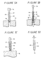
- FIGURES 5A through 5D are respectively diagrams showing processes of a method of manufacturing a shutter according to a third embodiment of the present invention, in which:
- FIGURE 1A shows a front surface side of a disc cartridge and FIGURE 1B shows a rear surface side thereof.
- a cartridge body 1 in which a magneto-optical disc D is accommodated.
- the cartridge body 1 is formed by combining an upper half 1a and a lower half 1b.
- the two halves 1a and 1b have opposing openings 2a, 2b through which the magneto-optical disc D accommodated therein is partly exposed in its radius direction.
- the lower half 1b has at its central portion a chucking central aperture 3 into which a disc rotation driving mechanism is inserted.
- the cartridge body 1 includes a shutter member 4 attached thereto so as to become freely slidable to open and/or close the two openings 2a, 2b.
- the shutter 4 includes plate-shaped portions 4a, 4b corresponding to the openings 2a, 2b of the cartridge body 1 and a coupling portion 4c for coupling the plate-shaped portions 4a, 4b and whose width is substantially equal to a thickness of the cartridge body 1.
- the whole of the shutter 4 is substantially U-letter in cross section.
- the shutter 4 is attached to the cartridge body 1 from its front end face 1c at the side so as to stride the cartridge body 1 where the openings 2a, 2b are formed. At that time, engagement protrusions 4c1, 4c2 formed on the coupling portion 4c of the shutter 4 are engaged with a guide groove 1d formed on the front end face 1c of the cartridge body 1 along its longitudinal direction. As a result, the shutter 4 opens or closes the openings 2a, 2b when it is slid.
- FIGURES 2A through 2F A manufacturing process of the shutter 4 thus arranged according to a first embodiment of the present invention will hereinafter be described with reference to FIGURES 2A through 2F.
- the shutter 4 is formed by a material 41 of a development-shape. More specifically, a pair of plate-shaped portions 4a, 4b and the coupling portion 4c are punched out from a plate-shaped metal material by a punch die 11 and a punch 12 so that the plate-shaped portions 4a, 4b and the coupling portion 4c are in flush with one another and coupled to one another, thereby the material 41 of the shutter 4 being formed.
- the material 41 of the shutter member 4 of the development shape (hereinafter simply referred to as "material” 41) is bent by a bending die 13 and a bending punch 14 such that the two plate portions 4a, 4b thereof are opposed substantially in parallel to each other across the coupling portion 4c.
- the material 41 is formed as substantially U-letter configuration in cross section.
- the two plate-shaped portions 4a, 4b of the material 41 that was formed as substantially U-letter configuration in cross section are bent such that a spacing between the free ends of the two plate-shaped portions 4a, 4b becomes narrower than the width of the coupling portion 4c. More specifically, as shown in FIGURE 2C, the two plate-shaped portions 4a, 4b are bent inwardly so that the opening width dimension W1 between the free end sides of the material 41 becomes narrower than an opening width dimension W of the shutter 4 that is the final product (W > W1).
- the material 41 that was shaped in substantially U-letter in cross section is again shaped in substantially U-letter in cross section by a setting die 15 and a setting punch 16.
- the setting die 15 used in the fourth process has a flat supporting surface 15a.
- a tip end portion 16a of the setting punch 16 is formed as a tapered surface in such a fashion that a thickness dimension of a tip end 16a1 thereof becomes smaller than the above-mentioned opening width dimension W1 between the two plate-shaped portions 4a, 4b of the material 41 having the deformed U-letter cross section and that a thickness dimension of a base portion 16a2 thereof is larger than the above-mentioned opening width dimension W of the shutter 4 that is the final product.
- the tapered surface tip end portion 16a of the setting die 16 is inserted with a pressure into the space between a pair of plate-shaped portions 4a and 4b from the space between their free ends.
- the tapered surface tip end portion 16a is further inserted between the two plate-shaped portions 4a and 4b with a pressure, whereby the spacing between the free end portions of the two plate-shaped portions 4a and 4b, i.e., the opening portion thereof is pushed outwardly by the base portion 16a2 of the tapered surface tip end portion 16a whose thickness dimension is larger than the opening width dimension W1.
- the two plate-shaped portions 4a, 4b are pushed outwardly relative to the coupling portion 4c and thereby bent slightly.
- the plate-shaped portions 4a, 4b are deformed by a flexibility of the material 41 so that the distance at the base end side serving as the coupling portion 4c and the spacing between the free end sides become equal to each other. More specifically, as shown in FIGURE 2F, there can be obtained the shutter 4 in which the spacing between the two plate shaped portions 4a and 4b becomes the aforementioned opening width dimension W therethrough as the final product.
- a residual stress produced in the shutter 4 when a pair of plate-shaped portions 4a, 4b of the shutter 4 are bent is converted from the (+) side to the (-) side as shown in FIGURE 2E and then alleviated.
- the spacing between a pair of plate-shaped portions 4a, 4b of the shutter 4 is selected to be the opening width dimension W of the final product, the above-mentioned spacing is held at the stable width dimension having less residual stress, i.e, such spacing is stably held at the spacing substantially equal to the thickness of the cartridge body 1.
- a temperature in the heat treatment process is set to be a temperature slightly higher than 80( ⁇ C) because the upper limit of a temperature at which the magneto-optical disc D accommodated in a disc cartridge to which the shutter 4 manufactured according to the present invention is attached is preserved is 80( ⁇ C).
- the above-mentioned heat treatment temperature is not limited to substantially 100( ⁇ C) and a temperature ranging from 0( ⁇ C) to 100( ⁇ C) may be properly selected checking the upper limit temperature at which the magneto optical disc D can be preserved.
- the shutter 4 is treated by heat in a furnace in which the shutter 4 is radiated with infrared rays.
- FIGURE 3 is a conceptual diagram showing a system in which a series of the above mentioned processes can be carried out to manufacture the shutter 4.
- a material plate i.e., a plate-shaped metal material 40, such as a stainless steel, aluminum plate or the like wound on a bobbin 17 is transported to a press work machine 18.
- This press work machine 18 carries out the above-mentioned processes shown in FIGURES 2A to 2F, i.e., the first process in which the material 41 is punched out therefrom, the second process in which the material 41 is bent in substantially U-letter shape, the third process in which the two plate-shaped portions 4a, 4b are bent toward the inside and the fourth process in which the two plate-shaped portions 4a, 4b are slightly bent when they are pressed outwardly. Then, the aforesaid shutter 4 is shaped by this press work machine 18.
- the shutter 4 thus shaped is transported on a belt conveyor 19 and then transported by the belt conveyor 19 to a heat treatment furnace 20, in which it is treated by heat at the aforesaid temperature to provide the shutter 4 as the final product.
- FIGURES 4A to 4D show a second embodiment of the bending work process of the shutter 4.
- One of the most specific features of the second embodiment of the present invention lies in a bending work process in which the two plate-shaped portions 4a, 4b are bent inwardly.
- This bending work process according to the second embodiment corresponds to the third process in the bending work processes shown in FIGURES 2A to 2F.
- the material 41 of the shutter 4 in the developed state is bent by the first bending die 13 and the first bending punch 14 in such a manner as to cause a pair of plate-shaped portions 4a, 4b to oppose to each other across the coupling portion 4c in substantially parallel to each other, and then shaped in substantially U-letter configuration.
- the material 41 whose cross section is substantially U-letter configuration is processed by a second bending die 23 and a second bending punch 24 as shown in FIGURE 4B with the result that the pair of plate-shaped portions 4a, 4b are bent inwardly as shown in FIGURE 4B.
- the second bending die 23 includes a slide die 25, a slide cam 26 for pressing the slide die 25 and a return spring 27 for the slide die 25.
- the second bending punch 24 is formed as an inverse tapered surface such that a thickness dimension of a tip end 24a1 of a tip end portion 24a becomes equal to the opening width dimension W of the final product mentioned above and that a thickness dimension of a base portion 24a2 of the tip end portion 24a becomes the dimension W1 which is smaller than the opening width dimension W.
- the slide die 25 is urged against the base end side of the material 41 under the condition that the bending punch 24 is inserted from the free end sides of the pair of plate-shaped portions 4a, 4b of the material 41. Under this condition, when the slide cam 26 is moved downwardly, the slide die 25 is moved in the directions shown by arrows in FIGURE 4B with the result that the material 41 is shaped. After the material 41 has finished being shaped, the slide die 25 is spaced apart from the material 41 by the return springs 27 and the slide cam 26 also is moved upwardly.
- the two plate-shaped portions 4a, 4b of the material 41 are inwardly bent such that a relationship between the base end side width dimension W thereof and the free end side width dimension W1 thereof satisfies W > W1 similarly to the case shown in FIGURE 2C. Therefore, the material 41 is shaped in substantially U-letter configuration in cross section.
- the material 41 whose cross section is substantially U-letter configuration is subjected to the setting work in which the two plate-shaped portions 4a, 4b are pressed outwardly and then set in the bent state by the setting die 15 and the setting punch 16 similarly to the aforesaid fourth process shown in FIGURES 2D and 2E.
- the shutter 4 in which the whole spacing between the pair of plate-shaped portions 4a, 4b becomes the aforementioned opening width dimension W as a final product as shown in FIGURE 4D.
- the two plate-shaped portions 4a, 4b can be bent inwardly relative to the coupling portion 4c equally and reliably.
- FIGURES 5A through 5D show a third embodiment of the fourth bending work process according to the present invention. Also in the third embodiment, one of the most specific features thereof lies in that the bending work process for bending the two plate-shaped portions 4a, 4b inwardly. This bending work process corresponds to the third process in the bending work processes shown in FIGURES 2A through 2E.
- the two plate-shaped portions 4a, 4b are bent across the coupling portion 4c so as to oppose to each other in substantially parallel to each other, and the material 41 is shaped in substantially U-letter configuration in cross section.
- the two plate-shaped portions 4a, 4b of the material 41 are bent inwardly by a second bending die 33 and a second bending punch 34 as shown in FIGURE 5B.
- a thickness dimension E1 of a tip end portion 34a thereof is set to be smaller than an inner width dimension E of the material 41 (E > E1) as shown in FIGURE 4B.
- the material 41 which was shaped in deformed U-letter configuration in cross section is treated by the setting work process by the setting die 15 and the setting punch 15 similarly to the aforesaid first and second embodiments as shown in FIGURE 5C.
- the shutter 4 in which the whole spacing between the two plate-shaped portions 4a and 4b becomes the aforesaid opening width dimension W as shown in FIGURE 5D.
- a mold structure used in the bending work process in which the two plate-shaped portions 4a, 4b are bend inwardly can be simplified.
- the residual stress can be removed substantially completely by treating the shutter 4 shaped as the final product by heat similarly to the first embodiment, and therefore the spacing between the two plate-shaped portions 4a and 4b can be held more stably.
- the present invention is applied to the manufacturing process for manufacturing the shutter of the disc cartridge in which the magneto-optical disc is accommodated as described above, the present invention is not limited thereto and may also be applied to shutters of substantially U-letter configuration in cross section that are attached to a variety of cartridges for accommodating therein recording media, such as a floppy disk or the like.
- the shape or the like of the shutter is not limited to the above-mentioned one and may be properly varied freely.
Landscapes
- Punching Or Piercing (AREA)
Description
Claims (9)
- A manufacturing method of a shutter (4) for a cartridge (1) which is accommodating therein a recording medium, comprising the steps of:a first process for punching out a plate-shaped metal material (41) so as to provide a shutter (4) in a developed shape having a pair of plate-shaped portions (4a,4b) and a coupling portion (4c) for coupling said pair of plate-shaped portions (4a,4b);a second process for shaping the member (41) shaped by said first process such that said pair of plate-shaped portions (4a,4b) are opposed to each other across said coupling portion (42) and that a spacing (W1) between free end sides of said pair of plate-shaped portions (4a,4b) becomes narrower than a spacing (W) of said pair of plate-shaped portions (4a,4b) at its portion coupled by said coupling portion (4c); characterized bya third process for shaping said member (41) such that a spacing (W) between free ends of said pair of plate-shaped portions (4a,4b) of said member (41) shaped by said second process becomes substantially equal to a spacing (W) of said pair of plate-shaped portions (4a,4b) at its portion coupled by said coupling member (4c).
- A manufacturing method according to claim 1, wherein said third process is a process in which the spacing between the free ends of said pair of plate-shaped portions (4a,4b) of said member (41) shaped by said second process is temporarily widened more that the spacing of the portions (4a,4b) coupled by said coupling portion (4c).
- A manufacturing method according to claim 2, wherein said third process is carried out such that a mold (16) having such a shape that its thickness is reduced in its tip end portion (16a) and its portion corresponding to said free end sides of said pair of plate-shaped portions (4a,4b) is larger than the spacing of the portions coupled by said coupling member (4c) of said pair of plate-shaped portions (4a,4b) shaped by second process is inserted from said free end sides of said pair of plate-shaped portions (4a,4b) of said member (41) shaped by said second process.
- A manufacturing method according to claim 1, wherein said second process is comprised of a process for shaping said member (41) obtained by said first process in substantially U-letter configuration in cross section such that said pair of plate-shaped portions (4a,4b) are opposed to each other across said coupling portion (42) and a process for shaping said member (41) shaped by the preceding process in substantially U-letter configuration in cross section such that a spacing (W1) between the free end sides of said pair of plate-shaped portions (4a,4b) becomes narrower than a spacing (W) between said pair of plate-shaped portions (4a,4b) at its portions coupled by said coupling portion (4c).
- A manufacturing method according to claim 4, wherein said process in said second process for reducing the spacing is carried out by inserting a mold (24), in which its portion (24a2) corresponding to said free end sides of said member (41) which is shaped in substantially U-letter configuration in cross section is made narrower than at least a spacing (W) between said pair of plate-shaped portions (4a,4b) of the portion coupled by said coupling portion (4c), thereinto from said free end sides of said pair of plate-shaped portions (4a,4b).
- A manufacturing method according to claim 4, wherein said process in said second process for reducing the spacing is carried out by inserting a mold (34), in which a portion (34a) corresponding to said free end sides of said member (41) which is shaped in substantially U-letter configuration in cross section is made narrower than at least a spacing (E) between said pair of plate-shaped portions (4a,4b) of the portion coupled by said coupling portion (4c), thereinto from said free end sides of said pair of plate-shaped portions (4a,4b) and the portions coupled by said coupling portion (4c) of said pair of plate-shaped portions (4a,4b) of the member (41) shaped in U-letter configuration in cross section is shaped so as to reduce the spacing (E1) between said free end sides under the condition that said mold (34) is inserted.
- A manufacturing method according to claim 4, wherein said process in said second process for shaping said member (41) in U-letter configuration in cross section is carried out by using a mold (14), having a width substantially equal to that of said coupling portion (4c) and a mold (14) for shaping the member (41) obtained by said first process according to said mold (14).
- A manufacturing method according to claim 1, wherein said method further comprises a process for treating said member (41) obtained by said third process by heat at a temperature in which a residual stress can be removed.
- A manufacturing method according to claim 1, wherein said method further comprises a process for treating said member (41) obtained by said third process by heat at a temperature near an upper limit of an ambient temperature in which said member (41) is used as a shutter (4).
Applications Claiming Priority (2)
| Application Number | Priority Date | Filing Date | Title |
|---|---|---|---|
| JP01397693A JP3159341B2 (en) | 1993-01-29 | 1993-01-29 | Method of manufacturing shutter member |
| JP13976/93 | 1993-01-29 |
Publications (3)
| Publication Number | Publication Date |
|---|---|
| EP0609150A2 EP0609150A2 (en) | 1994-08-03 |
| EP0609150A3 EP0609150A3 (en) | 1995-01-25 |
| EP0609150B1 true EP0609150B1 (en) | 1998-09-02 |
Family
ID=11848262
Family Applications (1)
| Application Number | Title | Priority Date | Filing Date |
|---|---|---|---|
| EP94400174A Expired - Lifetime EP0609150B1 (en) | 1993-01-29 | 1994-01-27 | Method of manufacturing a shutter for a disc cartridge |
Country Status (4)
| Country | Link |
|---|---|
| US (1) | US5454251A (en) |
| EP (1) | EP0609150B1 (en) |
| JP (1) | JP3159341B2 (en) |
| DE (1) | DE69412874T2 (en) |
Families Citing this family (4)
| Publication number | Priority date | Publication date | Assignee | Title |
|---|---|---|---|---|
| JPH08221936A (en) * | 1995-02-14 | 1996-08-30 | Sony Corp | Original shutter for disc cartridge and shutter and disc cartridge |
| US6510131B1 (en) * | 2000-02-16 | 2003-01-21 | Imation Corp. | Data storage disk cartridge including a shutter assembly with a stress relief mechanism |
| JP2001297555A (en) * | 2000-04-14 | 2001-10-26 | Sony Corp | Disc cartridge and shutter, and method and apparatus for manufacturing the same. |
| KR101014030B1 (en) * | 2008-08-29 | 2011-02-14 | 현대자동차주식회사 | Wiring Mounting Flange and Manufacturing Process |
Family Cites Families (18)
| Publication number | Priority date | Publication date | Assignee | Title |
|---|---|---|---|---|
| US3550422A (en) * | 1969-04-01 | 1970-12-29 | North American Rockwell | Creep-form tooling |
| JPS59132470A (en) * | 1983-01-18 | 1984-07-30 | Sumitomo Bakelite Co Ltd | Bending processing method of thermoplastic resin sheet |
| JPH0640427B2 (en) * | 1985-01-24 | 1994-05-25 | ソニー株式会社 | Method of manufacturing shutter for magnetic disk cassette |
| SU1388141A1 (en) * | 1986-09-15 | 1988-04-15 | Украинский научно-исследовательский институт металлов | Method of producing u=shaped roll-formed sections |
| JPS63253581A (en) * | 1987-04-10 | 1988-10-20 | Matsushita Electric Ind Co Ltd | disk cartridge |
| DE3739173A1 (en) * | 1987-11-19 | 1989-06-01 | Feintool Int Holding | METHOD AND DEVICE FOR BENDING WORKPIECES |
| JP2595654B2 (en) * | 1988-05-23 | 1997-04-02 | ソニー株式会社 | Disc cartridge shutter and method of manufacturing the same |
| EP0353000B1 (en) * | 1988-07-26 | 1994-09-14 | Hitachi Maxell Ltd. | A shutter of a disk cartridge, apparatus for and method of its manufacture |
| JP2505277B2 (en) * | 1989-03-29 | 1996-06-05 | 日立マクセル株式会社 | Disk cartridge manufacturing apparatus and manufacturing method |
| US5021913A (en) * | 1989-04-24 | 1991-06-04 | Overland Bolling Company | Shutter for covering a window opening in a case that contains a flexible disk |
| IE891454L (en) * | 1989-05-04 | 1990-11-04 | Bray Prec Tooling Co Ltd | Forming a micro disc shutter |
| US5036421A (en) * | 1989-05-31 | 1991-07-30 | Tdk Corporation | Disc cartridge having an improved shutter configuration |
| JPH0394917A (en) * | 1989-09-07 | 1991-04-19 | Nakajima Kokan Kk | Deep bending method for extremely thick steel plate and its device |
| JPH0773739B2 (en) * | 1989-09-13 | 1995-08-09 | 日鐵建材工業株式会社 | Cold roll forming method and apparatus |
| JP2993127B2 (en) * | 1990-12-14 | 1999-12-20 | ソニー株式会社 | Disk cassette shutter and disk cassette using the shutter |
| US5099675A (en) * | 1991-01-25 | 1992-03-31 | Century Manufacturing Co., Inc. | Punch and die assembly for bending operations |
| US5527606A (en) * | 1991-07-25 | 1996-06-18 | Sony Corporation | Disk cassette shutter |
| JP3103902B2 (en) * | 1991-08-23 | 2000-10-30 | ソニー株式会社 | Manufacturing method of shutter |
-
1993
- 1993-01-29 JP JP01397693A patent/JP3159341B2/en not_active Expired - Fee Related
-
1994
- 1994-01-26 US US08/186,577 patent/US5454251A/en not_active Expired - Fee Related
- 1994-01-27 DE DE69412874T patent/DE69412874T2/en not_active Expired - Fee Related
- 1994-01-27 EP EP94400174A patent/EP0609150B1/en not_active Expired - Lifetime
Also Published As
| Publication number | Publication date |
|---|---|
| EP0609150A3 (en) | 1995-01-25 |
| DE69412874D1 (en) | 1998-10-08 |
| US5454251A (en) | 1995-10-03 |
| JP3159341B2 (en) | 2001-04-23 |
| EP0609150A2 (en) | 1994-08-03 |
| DE69412874T2 (en) | 1999-03-04 |
| JPH06223529A (en) | 1994-08-12 |
Similar Documents
| Publication | Publication Date | Title |
|---|---|---|
| EP0652563B1 (en) | Disc Cartridge | |
| GB2102186A (en) | Disc-accommodating case | |
| US6034850A (en) | Two-part tape cartridge reel locking mechanism | |
| EP0609150A2 (en) | Method of manufacturing a shutter for a disc cartridge | |
| EP0147513A1 (en) | Tape cassette dust door spring assembly and method for assembling same | |
| US5364583A (en) | Method and device for removing an injection-molded piece from a mold | |
| EP0343844A2 (en) | Disc cartridge shutters and methods of producing same | |
| DE69525242T2 (en) | CHARGER FOR STORAGE MEDIUM AND RECORDING AND / OR PLAYBACK DEVICE | |
| US4853817A (en) | Magnetic disk cartridge | |
| US20080197225A1 (en) | Recording tape cartridge | |
| JPH0632183B2 (en) | Assembly device for magnetic disk cartridge | |
| EP0620554B1 (en) | System comprising tape cartridge and recording/reproducing apparatus for the tape cartridge | |
| EP0459743B1 (en) | Disc cartridges and methods of manufacturing such cartridges | |
| EP0772197A2 (en) | Tape cassette and metal mold device for molding tape cassette halves | |
| US20020109940A1 (en) | Cartridge and manufacturing method thereof | |
| EP0762418B1 (en) | Disk-use hub, disk cartridge, and disk driving device | |
| JP2993127B2 (en) | Disk cassette shutter and disk cassette using the shutter | |
| US5511736A (en) | Tape cassette and guide pin | |
| US7218477B2 (en) | Information recording medium cartridge | |
| JPH0142849Y2 (en) | ||
| JP2545237Y2 (en) | Disk cartridge | |
| JP3515002B2 (en) | Cartridge and manufacturing method thereof | |
| EP0540336B1 (en) | Magnetic tape cassette | |
| US5484117A (en) | Reel spring for a thin-walled videocassette | |
| EP0973164A1 (en) | Disc cartridge and method and apparatus for manufacture therefor |
Legal Events
| Date | Code | Title | Description |
|---|---|---|---|
| PUAI | Public reference made under article 153(3) epc to a published international application that has entered the european phase |
Free format text: ORIGINAL CODE: 0009012 |
|
| AK | Designated contracting states |
Kind code of ref document: A2 Designated state(s): DE FR GB |
|
| PUAL | Search report despatched |
Free format text: ORIGINAL CODE: 0009013 |
|
| AK | Designated contracting states |
Kind code of ref document: A3 Designated state(s): DE FR GB |
|
| 17P | Request for examination filed |
Effective date: 19950621 |
|
| GRAG | Despatch of communication of intention to grant |
Free format text: ORIGINAL CODE: EPIDOS AGRA |
|
| 17Q | First examination report despatched |
Effective date: 19970818 |
|
| GRAG | Despatch of communication of intention to grant |
Free format text: ORIGINAL CODE: EPIDOS AGRA |
|
| GRAH | Despatch of communication of intention to grant a patent |
Free format text: ORIGINAL CODE: EPIDOS IGRA |
|
| GRAH | Despatch of communication of intention to grant a patent |
Free format text: ORIGINAL CODE: EPIDOS IGRA |
|
| GRAA | (expected) grant |
Free format text: ORIGINAL CODE: 0009210 |
|
| AK | Designated contracting states |
Kind code of ref document: B1 Designated state(s): DE FR GB |
|
| REF | Corresponds to: |
Ref document number: 69412874 Country of ref document: DE Date of ref document: 19981008 |
|
| ET | Fr: translation filed | ||
| PLBE | No opposition filed within time limit |
Free format text: ORIGINAL CODE: 0009261 |
|
| STAA | Information on the status of an ep patent application or granted ep patent |
Free format text: STATUS: NO OPPOSITION FILED WITHIN TIME LIMIT |
|
| 26N | No opposition filed | ||
| REG | Reference to a national code |
Ref country code: GB Ref legal event code: IF02 |
|
| PGFP | Annual fee paid to national office [announced via postgrant information from national office to epo] |
Ref country code: FR Payment date: 20030110 Year of fee payment: 10 |
|
| PGFP | Annual fee paid to national office [announced via postgrant information from national office to epo] |
Ref country code: GB Payment date: 20030122 Year of fee payment: 10 |
|
| PGFP | Annual fee paid to national office [announced via postgrant information from national office to epo] |
Ref country code: DE Payment date: 20030206 Year of fee payment: 10 |
|
| PG25 | Lapsed in a contracting state [announced via postgrant information from national office to epo] |
Ref country code: GB Free format text: LAPSE BECAUSE OF NON-PAYMENT OF DUE FEES Effective date: 20040127 |
|
| PG25 | Lapsed in a contracting state [announced via postgrant information from national office to epo] |
Ref country code: DE Free format text: LAPSE BECAUSE OF NON-PAYMENT OF DUE FEES Effective date: 20040803 |
|
| GBPC | Gb: european patent ceased through non-payment of renewal fee |
Effective date: 20040127 |
|
| PG25 | Lapsed in a contracting state [announced via postgrant information from national office to epo] |
Ref country code: FR Free format text: LAPSE BECAUSE OF NON-PAYMENT OF DUE FEES Effective date: 20040930 |
|
| REG | Reference to a national code |
Ref country code: FR Ref legal event code: ST |