EP0353000B1 - A shutter of a disk cartridge, apparatus for and method of its manufacture - Google Patents
A shutter of a disk cartridge, apparatus for and method of its manufacture Download PDFInfo
- Publication number
- EP0353000B1 EP0353000B1 EP89307490A EP89307490A EP0353000B1 EP 0353000 B1 EP0353000 B1 EP 0353000B1 EP 89307490 A EP89307490 A EP 89307490A EP 89307490 A EP89307490 A EP 89307490A EP 0353000 B1 EP0353000 B1 EP 0353000B1
- Authority
- EP
- European Patent Office
- Prior art keywords
- shutter
- disposed
- edge
- gate
- injection
- Prior art date
- Legal status (The legal status is an assumption and is not a legal conclusion. Google has not performed a legal analysis and makes no representation as to the accuracy of the status listed.)
- Expired - Lifetime
Links
Images


Classifications
-
- G—PHYSICS
- G11—INFORMATION STORAGE
- G11B—INFORMATION STORAGE BASED ON RELATIVE MOVEMENT BETWEEN RECORD CARRIER AND TRANSDUCER
- G11B23/00—Record carriers not specific to the method of recording or reproducing; Accessories, e.g. containers, specially adapted for co-operation with the recording or reproducing apparatus ; Intermediate mediums; Apparatus or processes specially adapted for their manufacture
- G11B23/02—Containers; Storing means both adapted to cooperate with the recording or reproducing means
- G11B23/03—Containers for flat record carriers
-
- B—PERFORMING OPERATIONS; TRANSPORTING
- B29—WORKING OF PLASTICS; WORKING OF SUBSTANCES IN A PLASTIC STATE IN GENERAL
- B29C—SHAPING OR JOINING OF PLASTICS; SHAPING OF MATERIAL IN A PLASTIC STATE, NOT OTHERWISE PROVIDED FOR; AFTER-TREATMENT OF THE SHAPED PRODUCTS, e.g. REPAIRING
- B29C45/00—Injection moulding, i.e. forcing the required volume of moulding material through a nozzle into a closed mould; Apparatus therefor
- B29C45/17—Component parts, details or accessories; Auxiliary operations
- B29C45/26—Moulds
- B29C45/33—Moulds having transversely, e.g. radially, movable mould parts
-
- G—PHYSICS
- G11—INFORMATION STORAGE
- G11B—INFORMATION STORAGE BASED ON RELATIVE MOVEMENT BETWEEN RECORD CARRIER AND TRANSDUCER
- G11B23/00—Record carriers not specific to the method of recording or reproducing; Accessories, e.g. containers, specially adapted for co-operation with the recording or reproducing apparatus ; Intermediate mediums; Apparatus or processes specially adapted for their manufacture
- G11B23/02—Containers; Storing means both adapted to cooperate with the recording or reproducing means
- G11B23/03—Containers for flat record carriers
- G11B23/0301—Details
- G11B23/0308—Shutters
-
- G—PHYSICS
- G11—INFORMATION STORAGE
- G11B—INFORMATION STORAGE BASED ON RELATIVE MOVEMENT BETWEEN RECORD CARRIER AND TRANSDUCER
- G11B23/00—Record carriers not specific to the method of recording or reproducing; Accessories, e.g. containers, specially adapted for co-operation with the recording or reproducing apparatus ; Intermediate mediums; Apparatus or processes specially adapted for their manufacture
- G11B23/02—Containers; Storing means both adapted to cooperate with the recording or reproducing means
- G11B23/03—Containers for flat record carriers
- G11B23/033—Containers for flat record carriers for flexible discs
- G11B23/0332—Containers for flat record carriers for flexible discs for single discs, e.g. envelopes
Definitions
- the present invention relates to a shutter for a disk cartridge including a cartridge casing rotatably accommodating a recording medium disk, e.g. a magnetic disk, a photo disk or a photo-magnetic disk.
- the shutter is made of a synthetic resin and is provided for opening and closing a read/write window formed in the cartridge casing.
- the present invention further relates to a manufacturing apparatus for the shutter and a manufacturing method thereof.
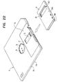
- a disk cartridge shown in Figure 22 of the accompanying drawings is one known such cartridge.
- the disk cartridge shown in Figure 22 comprises a cartridge casing 1 formed by combining two casing halves 1a and 1b together, both made of synthetic resin, and a flexible magnetic disk 2 rotatably accommodated in the casing 1.
- the magnetic disk 2 is provided at a centre portion thereof with a hub 3.
- the hub 3 is exposed through an opening 4 formed at a centre of the cartridge casing 1.
- a driving apparatus can rotate the magnetic disk 2 at a predetermined rotating speed through the hub 3.
- the cartridge casing 1 is provided at opposite sides thereof with rectangular recess portions 6.
- Read/write windows 5 are formed in the recess portions 6, into which a magnetic head can enter.
- a shutter 7 of U-shaped cross-section rides slidably astride the recess portions 6.
- the shutter 7 comprises two side plates 9a,9b and a connecting member 10 for connecting at one end the side plates 9a,9b.
- the shutter 7 further comprises a rectangular head access hole 8 of substantially the same dimension and shape as the window 5.
- the shutter 7 is elastically urged by a spring member accommodated therein (not shown) so as to close the windows 5.
- a spring member accommodated therein not shown
- the shutter is made of metal material or synthetic resin.
- the metal shutter may shave down sliding surfaces of the recess portions 6 by edge portions of the shutter 7 on sliding movement of the shutter 7 to provide shavings of the synthetic resin casing 1.
- the shavings may adhere to the surfaces of the magnetic disk 2 to cause recording and reproducing errors.
- an increased clearance is provided between the cartridge casing 1 and the shutter 7. In this case, foreign substances can easily enter from the outside into the casing 1 through the increased clearance. Accordingly, the foreign substances may adhere to the magnetic disk surfaces also to cause recording and reproducing errors.
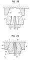
- the shutter 7 is made by the manufacturing apparatus shown in Figs. 23 and 24.
- a reference numeral 11 designates a stationary mould
- 12 designates a pair of side slide moulds
- 13 designates a core to be disposed between the side slide moulds 12 and 12′
- 14 and 14′ designate a pair of side locks
- 15 designates a cavity for the shutter
- 16 designates an ejecting pin slidably disposed in the core 13.
- the letter Z designates a mould clamping direction.
- the stationary mould 11, the side slide moulds 12, and the core 13 are so clamped together as to define thereamong the cavity 15 for the moulding operation.
- the side slide mound 12 abuts at a tapered portion 12a thereof against a tapered portion 14a of the slide lock 14 to clamp these moulds together under an appropriate clamping force.
- the moulds are held with a clamping force being applied thereto in the direction Z, and the synthetic resin is injected into the cavity 15 by means of injection means (not shown) to provide the mouldings.
- injection means not shown
- the side slide moulds 12 and 12 are separated from each other.
- The-moulded shutter 7 mounted on the core 13 is ejected therefrom by means of the ejecting pin 16.
- the force applied to the side locks 14 and 14′ may be nonuniform, or the abutting force against the core 13 from one side slide mould 12 may differ from that from the other side slide mould 12 due to dispersion of manufacturing accuracy. If the abutting forces differ from each other, the core 13 may incline towards either side thereof since the core 13 is thin (about 2.8 mm). As a result, the side plates 9a and 9b of the shutter 7 differ from each other in the thickness thereof. Further, molten resin enters between the side slide mould 12 and the core 13 which are abutted each other with lower abutting force to provide the mouldings with moulding flash.
- the core 13 is provided therein with a small straight bore for the ejecting pin 16.
- the core has, for example, a thickness of about 2.8 mm and a length of about 35 mm. Therefore, it is hard to provide the small straight bore (for example, 1.5 mm diameter) to the core 13 from the processing technical point of view.
- the ejecting pin 16 pushes the moulded shutter 7 at an inner wall surface of the connecting member 10 thereof to remove it from the core 13.
- a part of the connecting member 10 projects outwards or a moulding flash projects inwards from the inner wall surface of the connecting member 10.
- the shutter 7 is limited in the slide movement thereof by the stepped parts of the recess portions 6 of the casing 1.
- the side plates 9a and 9b of the shutter 7 extend apart from each other to widen an opening end A , the shutter 7 can slide beyond the stepped part ( Figure 25). Therefore, the hole 8 does not align with the windows 5 thus to disable the head from entering the windows 5.
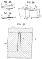
- a conventional shutter is formed to be of a U-shaped cross-section by bending a thin metal plate, for example, a stainless steel plate of a thickness of 0.2 mm.
- a thin metal plate for example, a stainless steel plate of a thickness of 0.2 mm.
- the metal shutter may readily shave down the synthetic resin casing and may be readily detached from the casing on drop impact.
- the shutter is formed integrally by means of injection moulding of synthetic resin.
- the moulds used in the injection moulding are so arranged, as shown in Fig. 27, that a core 13 is supported at opposite sides thereof by side slide moulds 12 and 12′ to define thereamong a longitudinal cavity for the shutter, and a stationary mould 11 is mounted on these moulds.
- the supporting force for the core 13 is one perpendicular to the clamping force for clamping the moulds 12 and 12′. Namely, such supporting force is one transmitted through the locking blocks and an angular pin and is not sufficient to withstand the injection pressure.
- the injection pressure of resin at the side of the core 13 into which resin is first injected urges the core 13 towards the other side. This causes a difference in thickness between the side plates.
- a cartridge casing 1 of a magnetic disk cartridge to which a conventional synthetic resin shutter 7 is mounted is provided with a recess 17.
- a pin 18 of a recording/reproducing apparatus enters into the recess 17 to abut against an edge of the shutter 7 and moves it from a closed position (shown in the drawings) to an open position in a direction X to open the hole 8.
- a gate is disposed at an edge of the connecting member 10 adjacent to the hole 8. Therefore, after the moulding, a tapered gate mark 19 is left at the edge of the connecting member 10 to extend towards the recess 17.
- the gate mark 19 prevents the pin 18 from engaging with the shutter 7 and may ride on the side plate 9a or 9b of the shutter 7. It becomes impossible to obtain reliability of the movement of the shutter 7.
- An object of the present invention is to provide a disk cartridge shutter which can be moulded without defective moulding and with a high efficiency of moulding, and to provide apparatus for, and a method of, manufacturing such a shutter.
- Another object of the present invention is to provide a shutter for a disk cartridge, which can be so moulded that the side plates thereof are somewhat in contact with each other or are close to each other to narrow an opening of the shutter, and to provide a manufacturing apparatus for such shutter.
- EP-A-0 201 870 discloses a shutter, apparatus for manufacturing the shutter and a method of manufacturing the shutter as referred to in the prior art portions of claims 1, 6 and 11, respectively.
- the shutter of the present invention as defined in claim 1, and as made in the apparatus and using the method of the invention as defined in claims 6 and 11 is advantageous in that both side plates reliably have the same thickness due to the method of moulding with ejection being transversely of the connecting plate between the two side plates.
- This improved construction provides a shutter for a disk cartridge, which can present a high reliability of movement thereof.
- the draft angle defined by opposite side surfaces of the slide core is held between 2° and 8°. According to this, due to the difference of cooling rate, the shutter is so moulded that free ends of the side plates, which define an opening end, come into contact with each other or come close to each other to narrow the opening end.
- the slide core for forming a space defined by the side plates of the shutter is slidable in a direction perpendicular to a mould opening direction, it becomes possible directly to support the slide core by means of the mould clamping force, thereby effectively preventing the side plates from differing from each other in the thickness thereof and improving the productivity of the shutter moulding.
- the shutter has opposite edges, one on which a shutter opening member of recording/reproducing apparatus is adapted to abut, and the other edge which is the only edge provided with a gate mark, or has a first injection gate disposed at a portion corresponding to one end of the shutter on which a shutter opening member of a recording/reproducing apparatus is adapted to abut, and a second injection gate disposed at a portion corresponding to the other edge of the shutter opposite to the one edge thereof, the second injection gate having a passage cross-section larger than that of the first injection gate.
- an injection moulding apparatus for a shutter includes a movable mould 21, a stationary mould 22 disposed above the movable mould 21, and a slide core 23 disposed between the moulds 21 and 22 to define therebetween a cavity 24 for a shutter.
- the mould 22, the slide core 23 and the mould 21 are to be clamped up in a claiming direction Z in order.
- the apparatus further includes an angular pin 25 and resin injection means 26.
- the base portion 28 is provided with a bore 29 through which the angular pin 25 extends. The slide core 23 can move along the angular pin 25.
- the injection means 26 injects molten synthetic resin, e.g. polypropylene, as moulding compound into the cavity 24 through a passage 27.
- molten synthetic resin e.g. polypropylene
- a moulded shutter 34 is retained on the movable mould 21.
- the shutter 34 has opposite side plates 35a and 35b, and a connecting plate 36 connecting one ends of the side plates 35a and 35b.
- a reference numeral 31 designates an ejection pin consisting of an ejecting plate portion 32 and a cylindrical body portion 33 from which the ejecting plate portion 32 extends.
- the ejection pin 31 is so disposed that an end of the ejecting plate portion 32 faces towards and abuts on a portion of the side plate 35a under a connecting portion 36a between the side plate 35a and the connecting plate 36.
- the ejection pin 31 pushes up the shutter 34 to remove it from the movable mould 21.
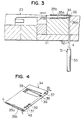
- the shutter 34 is, as shown in Fig. 4, provided on the side plate 35a thereof with two elongate ejection marks 37 and 37 which are somewhat recessed and each of which is placed on a portion including at least the connecting portion 36a.
- the ejecting plate portion 32 is so designed that a width W of the ejection mark 37 becomes substantially identical to a thickness t of the connecting plate 36.
- the ejecting plate portion 32 does not completely face to the connecting portion 36a only, but extend over the connecting portion 36a and the side plate 35a.
- the shutter can be ejected by means of means of pushing up a portion thereof including at least the connecting portion 36a by the ejection pin 31, the connecting plate 36 withstands an ejecting force from the ejection pin 31, as clearly seen from Fig. 3, on the ejection to prevent the shutter from deforming and to eject it from the mould 21 surely.
- the cartridge casing 40 consists of two casing halves 40a and 40b. Each of the halves 40a and 40b is provided on a predetermined portion thereof with a recess portion 41 which restricts the movement of the shutter within a predetermined range.
- a guide groove 42 is provided in the casing 40 to extend on the casing half 40a.
- a guide claw 39 extending inwardly from the side plate 35a with a predetermined inclination angle cooperates with the guide groove 42 to control the sliding movement of the shutter 34.
- the shutter 34 is elastically urged to close a magnetic head access hole 45 by means of a spring force of a spring 44.
- the spring 44 is engaged at one end thereof with a projection 43 projecting from an inner surface of the connecting plate 36 and at the other end thereof with an inner surface of the casing 40.
- the shutter 34 is tightly and slidably mounted on the recess portion 41 as well as is certainly stopped at opposite stepped portions, i.e. both ends of the recess portion 41.
- a magnetic disk cartridge according to another embodiment of the invention includes a cartridge casing 40, a magnetic disk 46 rotatably accommodated within the casing 40, and a shutter 34.
- the casing 40 consists of two casing halves 40a and 40b.
- the casing 40 is provided on opposite surfaces thereof with recess portions 41 and on an end face adjacent to the recess portions 41 with a guide groove 42. Further, the casing 40 is provided on the recess portions 41 with a head access hole 45 through which a magnetic head accesses the magnetic disk 46.
- two guide projections 39 are provided in the connecting plate 36 to extend perpendicular thereto. Both ends 48 and 48 of each of the guide projection 39 expand outwards in opposite directions perpendicular to the guide projection 39. The both ends 48 are received within the guide groove 42 so as to cooperate therewith to control the slide movement of the shutter 34.
- a reference numeral 50 designates a runner block.
- the slide core 49 is adapted to move along the angular pin 25 to remove from the movable mould 21 in a direction Y perpendicular to the mould clamping direction Z .
- the movable and the stationary moulds 21 and 22 are provided with projections 51 and 51, respectively. As clearly shown in Fig. 12, when clamped, these projections 51 and 51 abut to each other to form therebetween a cavity 39c for the guide projection 39. Accordingly, the shutter 34 is provided with windows 47 corresponding to the guide projections 39, which are formed by the projections 51. Further, the moulds 21 and 22 are provided with recess portions 52 and 52 for directly receiving a part of the slide core 49 (Fig. 12). The mould clamping force applied to the moulds 21 and 22 is directly transmitted to the slide core 49 so as to retain a tapered end portion of the slide core 49. According this, the slide core is prevented from being deflected by means of pressure of injected molten resin.
- This mould arrangement is applicable not only to the above-mentioned shutter which includes a guide projections projected from the connecting plate 36, but also to the shutter which includes a guide projections projected from the side plate 35a or 35b as shown in Fig. 6.
- a mould arrangement of an injection moulding apparatus for two-impression include gates 53 through which molten resin flowing in a runner 56 is injected into cavities for the shutters.
- the gate 53 is so disposed as to communicate at first with a part of the cavity corresponding to an edge 55b of the moulded shutter 34 opposite to an edge 55a thereof to which a shutter opening member 54 of a recording/reproducing apparatus is adapted to abut, namely an edge 55b apart from a hole 38.
- the gate 53 has a width (a dimension measured in a direction perpendicular to the drawing sheet) substantially identical to a height of the connecting plate 36.
- a gate mark is formed only in one edge 55b of the shutter 34, opposite to the other edge 55a to which the shutter opening member 54 is to be abutted. According this, when the shutter 34 is to be moved by means of the member 54, the gate mark never prevents the opening member 54 from engaging with the other edge 55a.
- the opening member 54 can engage with the edge 55a without riding onto the connecting plate 36, thereby surely moving the shutter to open the head access hole of the cartridge casing.
- the shutter 34 is provided at outer surfaces thereof with a plurality of straight projections 57 and of grooves 58 which are formed alternately.
- a mould arrangement of an injection moulding apparatus for two-impression includes a first gate 53-1 and a second gate 53-2 for each shutter, through which molten resin flowing in runners 56 is injected into a cavity for the shutter.
- the first gate 53-1 is so disposed as to communicate at first with a part of the cavity corresponding to an edge 55b of the moulded shutter 34 opposite to an edge 55a thereof which is adjacent to the hole 38a.
- the second gate 53-2 is so disposed as to communicate at first with a part of the cavity corresponding to the edge 55a of the moulded shutter 34.
- the molten resin is injected into a cavity simultaneously through the first gate 53-1 and the second gate 53-2 to mould the shutter 34.
- the first gate 53-1 has a cross-sectional area S1 greater than that S2 of the second gate 53-2 (S1 > S2).
- S1 greater than that S2 of the second gate 53-2
- the second gate 53-2 is provided with a constriction portion 59 to narrow the cross-sectional area thereof.
- no constriction portion 59 is provided in the first gate 53-1.
- the plan shape dimension of the second gate portion is identical to that of the first gage portion shown in Fig. 17.
- the gate mark formed on the edge 55a of the moulded shutter is necessarily smaller than that on the edge 55b.
- the periphery of the hole 38 is generally deformable under moulding pressure due to a lower rigidity thereof. According to this embodiment, if the injection is so controlled that the moulding pressure is applied to the first gate 53-1 more longer and is applied to the second gate 53-2 more shorter by means of shortening a gate seal time period, it becomes possible to improve the rigidity in the periphery of the hole 38 to prevent deformation thereof.
- the thicknesses in two parts 60 and 61 of the side plate 35a and 35b of the shutter 34 differ from each other, into which parts 60 and 61 the side plate is divided by a diagonal line (broken line).
- the fluidity resistance of molten resin in the part 60 is higher than that in the part 61 because an opening for the hole 38 is formed in the part 60 to generate two parts 62 and 62 of narrow width.
- the thickness of the side plate in the part 60 is substantially larger than that in the part 61.
- the thickness of the side plate is generally uniform and is t1 .
- the thickness of the side plate is gradually increased towards the side end of the shutter.
- the thickness in the side end of the shutter is t2 which is somewhat greater than t1
- the thickness in the boundary portion between the parts 60 and 61 is t1 . According this, it can be possible to eliminate generation of defective moulded shutter.
- this shutter 34 is also provided at outer surfaces thereof with a plurality of straight projections and of grooves as the shutter shown in Fig. 13 is.
- the side plate is divided into two parts 60 and 61 by a bisector (broken line).
- a bisector broken line
- an ejection mark is provided on a part of the outer surface of either side plate of the shutter including a part corresponding to the connecting portion of the connecting plate.
- the slide core becomes simple and then readily manufactured. Furthermore, it can be possible to shorten a cooling time period to improve an efficiency of moulding of the shutter with decrease of the defective one.
- the mould clamping force is directly applied to the slide core to support it, the deflection of the slide core on the moulding is prevented, thereby eliminating the thickness deviation in the side plates of the shutter and the moulding flash.
- the shutter moulded with a high accuracy in the dimension thereof can be obtained.
- the gate mark is provided only on an edge of the shutter opposite to an edge thereof to which a shutter opening member is adapted to abut. Therefore, it is eliminated that the gate mark prevents the opening member from engaging with side end of the shutter and then prevents the driving of the shutter. Improved is a reliability on the driving of the shutter to open the head access window of the cartridge casing.
Landscapes
- Engineering & Computer Science (AREA)
- Manufacturing & Machinery (AREA)
- Mechanical Engineering (AREA)
- Moulds For Moulding Plastics Or The Like (AREA)
Description
- The present invention relates to a shutter for a disk cartridge including a cartridge casing rotatably accommodating a recording medium disk, e.g. a magnetic disk, a photo disk or a photo-magnetic disk. The shutter is made of a synthetic resin and is provided for opening and closing a read/write window formed in the cartridge casing. The present invention further relates to a manufacturing apparatus for the shutter and a manufacturing method thereof.
- A disk cartridge shown in Figure 22 of the accompanying drawings is one known such cartridge.
- The disk cartridge shown in Figure 22 comprises a cartridge casing 1 formed by combining two casing halves 1a and 1b together, both made of synthetic resin, and a flexible magnetic disk 2 rotatably accommodated in the casing 1. The magnetic disk 2 is provided at a centre portion thereof with a
hub 3. Thehub 3 is exposed through an opening 4 formed at a centre of the cartridge casing 1. A driving apparatus can rotate the magnetic disk 2 at a predetermined rotating speed through thehub 3. - The cartridge casing 1 is provided at opposite sides thereof with
rectangular recess portions 6. Read/writewindows 5 are formed in therecess portions 6, into which a magnetic head can enter. A shutter 7 of U-shaped cross-section rides slidably astride therecess portions 6. - The shutter 7 comprises two
side plates member 10 for connecting at one end theside plates head access hole 8 of substantially the same dimension and shape as thewindow 5. The shutter 7 is elastically urged by a spring member accommodated therein (not shown) so as to close thewindows 5. By moving the shutter 7 against the spring force of the spring member to abut the stepped part of therecess portion 6, theaccess hole 8 is aligned with thewindows 5 to open them, thereby permitting the magnetic head to access the magnetic disk 2. - The shutter is made of metal material or synthetic resin. The metal shutter may shave down sliding surfaces of the
recess portions 6 by edge portions of the shutter 7 on sliding movement of the shutter 7 to provide shavings of the synthetic resin casing 1. The shavings may adhere to the surfaces of the magnetic disk 2 to cause recording and reproducing errors. In order to prevent such errors, an increased clearance is provided between the cartridge casing 1 and the shutter 7. In this case, foreign substances can easily enter from the outside into the casing 1 through the increased clearance. Accordingly, the foreign substances may adhere to the magnetic disk surfaces also to cause recording and reproducing errors. - Use of a synthetic resin shutter can eliminate the problem pertaining to the shavings. Accordingly, it is possible that the shutter 7 is so moulded as to closely and elastically ride astride the
recess portions 6, thereby preventing the foreign substances entering into the casing 1 through the shutter portion. - The shutter 7 is made by the manufacturing apparatus shown in Figs. 23 and 24. In the drawings, a reference numeral 11 designates a stationary mould; 12 designates a pair of side slide moulds; 13 designates a core to be disposed between the
side slide moulds core 13. The letter Z designates a mould clamping direction. - In Fig. 24, the stationary mould 11, the
side slide moulds 12, and thecore 13 are so clamped together as to define thereamong thecavity 15 for the moulding operation. The side slide mound 12 abuts at atapered portion 12a thereof against a tapered portion 14a of theslide lock 14 to clamp these moulds together under an appropriate clamping force. - The moulds are held with a clamping force being applied thereto in the direction Z, and the synthetic resin is injected into the
cavity 15 by means of injection means (not shown) to provide the mouldings. After cooling of the mouldings, theside slide moulds core 13 is ejected therefrom by means of the ejectingpin 16. - In these conventional manufacturing apparatus, the force applied to the
side locks core 13 from oneside slide mould 12 may differ from that from the otherside slide mould 12 due to dispersion of manufacturing accuracy. If the abutting forces differ from each other, thecore 13 may incline towards either side thereof since thecore 13 is thin (about 2.8 mm). As a result, theside plates side slide mould 12 and thecore 13 which are abutted each other with lower abutting force to provide the mouldings with moulding flash. - Further, the
core 13 is provided therein with a small straight bore for the ejectingpin 16. The core has, for example, a thickness of about 2.8 mm and a length of about 35 mm. Therefore, it is hard to provide the small straight bore (for example, 1.5 mm diameter) to thecore 13 from the processing technical point of view. - The ejecting
pin 16 pushes the moulded shutter 7 at an inner wall surface of the connectingmember 10 thereof to remove it from thecore 13. As a result, a part of the connectingmember 10 projects outwards or a moulding flash projects inwards from the inner wall surface of the connectingmember 10. These projections reduce the slidability of the shutter 7. - In order to overcome the problems pertaining to the projection, it is preferable that a longer time is taken to cool the mouldings (shutters 7) and to eject them after complete curing thereof. However, as a result, a total time period for moulding operation (moulding cycle) is prolonged.
- As described above, the shutter 7 is limited in the slide movement thereof by the stepped parts of the
recess portions 6 of the casing 1. However, if theside plates hole 8 does not align with thewindows 5 thus to disable the head from entering thewindows 5. - Even though the
side plates side plates - Furthermore, if the
side plates recess portion 6 becomes so large as to interfere with the slidability of the shutter 7 (Figure 26). - A conventional shutter is formed to be of a U-shaped cross-section by bending a thin metal plate, for example, a stainless steel plate of a thickness of 0.2 mm. However, it is difficult for bending process to obtain a higher accuracy in the dimension of the shutter. Further, the metal shutter may readily shave down the synthetic resin casing and may be readily detached from the casing on drop impact. For these reasons, it is proposed that the shutter is formed integrally by means of injection moulding of synthetic resin.
- The moulds used in the injection moulding are so arranged, as shown in Fig. 27, that a
core 13 is supported at opposite sides thereof byside slide moulds - In this arrangement, the supporting force for the
core 13 is one perpendicular to the clamping force for clamping themoulds core 13, the injection pressure of resin at the side of thecore 13 into which resin is first injected urges thecore 13 towards the other side. This causes a difference in thickness between the side plates. - As shown in Fig. 28, a cartridge casing 1 of a magnetic disk cartridge to which a conventional synthetic resin shutter 7 is mounted, is provided with a
recess 17. Apin 18 of a recording/reproducing apparatus enters into therecess 17 to abut against an edge of the shutter 7 and moves it from a closed position (shown in the drawings) to an open position in a direction X to open thehole 8. - For the moulding of such shutter 7, a gate is disposed at an edge of the connecting
member 10 adjacent to thehole 8. Therefore, after the moulding, atapered gate mark 19 is left at the edge of the connectingmember 10 to extend towards therecess 17. - The
gate mark 19 prevents thepin 18 from engaging with the shutter 7 and may ride on theside plate - An object of the present invention is to provide a disk cartridge shutter which can be moulded without defective moulding and with a high efficiency of moulding, and to provide apparatus for, and a method of, manufacturing such a shutter.
- Another object of the present invention is to provide a shutter for a disk cartridge, which can be so moulded that the side plates thereof are somewhat in contact with each other or are close to each other to narrow an opening of the shutter, and to provide a manufacturing apparatus for such shutter.
- EP-A-0 201 870 discloses a shutter, apparatus for manufacturing the shutter and a method of manufacturing the shutter as referred to in the prior art portions of
claims 1, 6 and 11, respectively. - The shutter of the present invention as defined in claim 1, and as made in the apparatus and using the method of the invention as defined in
claims 6 and 11 is advantageous in that both side plates reliably have the same thickness due to the method of moulding with ejection being transversely of the connecting plate between the two side plates. This improved construction provides a shutter for a disk cartridge, which can present a high reliability of movement thereof. - With the apparatus of the invention as defined in
claim 6, no ejection means is provided within the slide core, and the ejection means abuts on the thickest part of the shutter, namely a part corresponding to a connecting part of the connecting plate. Therefore, even though it may not be fully cooled due to insufficient cooling time, the shutter is hardly deformed on moulding. Furthermore, since the stationary mould, the slide core and the movable mould are placed in a clamping position in order and then the slide core is directly supported by means of mould clamping force, the slide core is hardly deflected on mould clamping. It becomes possible to mould the shutter with uniform thickness, thereby preventing the moulding flash from generating in the shutter. - Preferably, the draft angle defined by opposite side surfaces of the slide core is held between 2° and 8°. According to this, due to the difference of cooling rate, the shutter is so moulded that free ends of the side plates, which define an opening end, come into contact with each other or come close to each other to narrow the opening end.
- Because, with the apparatus and method of the invention, the slide core for forming a space defined by the side plates of the shutter is slidable in a direction perpendicular to a mould opening direction, it becomes possible directly to support the slide core by means of the mould clamping force, thereby effectively preventing the side plates from differing from each other in the thickness thereof and improving the productivity of the shutter moulding.
- In various embodiments, the shutter has opposite edges, one on which a shutter opening member of recording/reproducing apparatus is adapted to abut, and the other edge which is the only edge provided with a gate mark, or has a first injection gate disposed at a portion corresponding to one end of the shutter on which a shutter opening member of a recording/reproducing apparatus is adapted to abut, and a second injection gate disposed at a portion corresponding to the other edge of the shutter opposite to the one edge thereof, the second injection gate having a passage cross-section larger than that of the first injection gate.
- According to this, either no gate mark is formed on the edge of the shutter, on which the shutter opening member of the recording/reproducing apparatus is adapted to abut, or if a gate mark is provided, it is so small that the shutter opening member does not ride on such edge. Therefore, the shutter is moved certainly to open the head access hole in use of the disk cartridge.
- Other objects and features of the present invention will be more apparent from the following description of the preferred embodiments described with referring to the accompanying drawings.
-
- Fig. 1 is a sectional view showing an injection moulding apparatus for a shutter according to an embodiment of the invention.
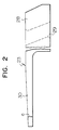
- Fig. 2 is a fragmentary side view showing a slide core in Fig. 1,
- Fig. 3 is a sectional view of the apparatus shown in Fig. 1 with moulded shutter, without a movable mould and a slide core,
- Fig. 4 is a perspective view showing a shutter formed by the apparatus shown in Fig. 1,
- Fig. 5 is a fragmentary plan view showing a magnetic disk cartridge to which the shutter shown in Fig. 4 is mounted,
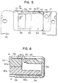
- Fig. 6 is an enlarged sectional view taken along the lines IV-IV in Fig. 5,
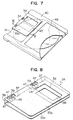
- Fig. 7 is a perspective view showing a magnetic disk cartridge to which a shutter according to an embodiment of the invention,
- Fig. 8 is an enlarged sectional view showing the shutter shown in Fig. 7,
- Fig. 9 is an enlarged sectional view taken along the lines IX-IX in Fig. 7,
- Fig. 10 is a fragmentary sectional view showing mounds when clamped,
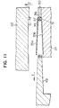
- Fig. 11 is a fragmentary sectional view showing the moulds when opened,
- Fig. 12 is a fragmentary sectional view showing a part of moulds corresponding to a guide claw portion of the shutter,
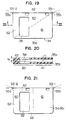
- Fig. 13 is a plan view showing two-impression moulded shutters formed in accordance with an embodiment of the invention,
- Fig. 14 is a fragmentary side view from the arrow XIV in Fig. 13,
- Fig. 15 is a plan view showing two-impression moulded shutters formed in accordance with another embodiment of the invention,
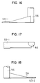
- Fig. 16 is an enlarged plan view showing one gate of the moulds,
- Fig. 17 is an enlarged side view showing the gate shown in Fig. 16,
- Fig. 18 is an enlarged plan view showing the other gate of the moulds,
- Fig. 19 is a plan view showing the shutter shown in Fig. 15,
- Fig. 20 is a sectional view taken along the lines XX-XX in Fig. 19,
- Fig. 21 is a plan view showing a shutter in accordance with still another embodiment of the invention,
- Fig. 22 is a perspective view showing a conventional magnetic disk cartridge,
- Fig. 23 is a sectional view showing moulds of a conventional moulding apparatus when opened,
- Fig. 24 is a sectional view showing the moulds of the conventional moulding apparatus when clamped,
- Figs. 25 and 26 are side views showing conventional shutter, respectively,
- Fig. 27 is a fragmentary sectional view showing a conventional shutter moulding apparatus, and
- Fig. 28 is a fragmentary plan view showing a conventional disk cartridge.
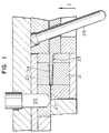
- Referring to Figs. 1 to 3, an injection moulding apparatus for a shutter includes a
movable mould 21, astationary mould 22 disposed above themovable mould 21, and aslide core 23 disposed between themoulds mould 22, theslide core 23 and themould 21 are to be clamped up in a claiming direction Z in order. The apparatus further includes anangular pin 25 and resin injection means 26. - As shown in detail in Fig. 2, the
slide core 23 includes abase portion 28 and abody portion 30 extending from thebase portion 28, which is to be disposed between themoulds base portion 28 is provided with a bore 29 through which theangular pin 25 extends. Theslide core 23 can move along theangular pin 25. - The injection means 26 injects molten synthetic resin, e.g. polypropylene, as moulding compound into the cavity 24 through a passage 27.
- After the injection is completed and a moulded object, i.e. a shutter, is cooled properly, as the
movable mould 21 opens, theslide core 23 moves along theangular pin 25 to become apart from themovable mould 21. - As shown in Fig. 3, as a result of mould opening, a moulded
shutter 34 is retained on themovable mould 21. Theshutter 34 hasopposite side plates plate 36 connecting one ends of theside plates reference numeral 31 designates an ejection pin consisting of an ejectingplate portion 32 and acylindrical body portion 33 from which theejecting plate portion 32 extends. Theejection pin 31 is so disposed that an end of the ejectingplate portion 32 faces towards and abuts on a portion of theside plate 35a under a connectingportion 36a between theside plate 35a and the connectingplate 36. Theejection pin 31 pushes up theshutter 34 to remove it from themovable mould 21. - The
shutter 34 is, as shown in Fig. 4, provided on theside plate 35a thereof with two elongate ejection marks 37 and 37 which are somewhat recessed and each of which is placed on a portion including at least the connectingportion 36a. The ejectingplate portion 32 is so designed that a width W of theejection mark 37 becomes substantially identical to a thickness t of the connectingplate 36. The ejectingplate portion 32 does not completely face to the connectingportion 36a only, but extend over the connectingportion 36a and theside plate 35a. According this, since the shutter can be ejected by means of means of pushing up a portion thereof including at least the connectingportion 36a by theejection pin 31, the connectingplate 36 withstands an ejecting force from theejection pin 31, as clearly seen from Fig. 3, on the ejection to prevent the shutter from deforming and to eject it from themould 21 surely. - If an draft angle a defined by opposite surfaces of the
body portion 30 of theslide core 23 is held between 2° and 8°, due to the cooling rate difference, the other ends of theside plates shutter 34 which defined by such other ends. Such shutter can exert a good braking ability and a good slidability thereof when mounted onto a cartridge casing. - The
cartridge casing 40, as shown in Figs. 5 and 6, consists of twocasing halves halves recess portion 41 which restricts the movement of the shutter within a predetermined range. Aguide groove 42 is provided in thecasing 40 to extend on thecasing half 40a. Aguide claw 39 extending inwardly from theside plate 35a with a predetermined inclination angle cooperates with theguide groove 42 to control the sliding movement of theshutter 34. Theshutter 34 is elastically urged to close a magnetichead access hole 45 by means of a spring force of aspring 44. Thespring 44 is engaged at one end thereof with aprojection 43 projecting from an inner surface of the connectingplate 36 and at the other end thereof with an inner surface of thecasing 40. - According to this embodiment, as described above, since the opening end A of the
shutter 34 is narrowed, theshutter 34 is tightly and slidably mounted on therecess portion 41 as well as is certainly stopped at opposite stepped portions, i.e. both ends of therecess portion 41. These features can be obtained by the shutter having a guide claw which projects from an inner surface of the connectingplate 36, instead of theguide claw 39. - Referring to Figs. 7 to 12, a magnetic disk cartridge according to another embodiment of the invention includes a
cartridge casing 40, amagnetic disk 46 rotatably accommodated within thecasing 40, and ashutter 34. Thecasing 40 consists of twocasing halves casing 40 is provided on opposite surfaces thereof withrecess portions 41 and on an end face adjacent to therecess portions 41 with aguide groove 42. Further, thecasing 40 is provided on therecess portions 41 with ahead access hole 45 through which a magnetic head accesses themagnetic disk 46. - In this embodiment, as shown in Figs. 8 and 9, two
guide projections 39 are provided in the connectingplate 36 to extend perpendicular thereto. Both ends 48 and 48 of each of theguide projection 39 expand outwards in opposite directions perpendicular to theguide projection 39. The both ends 48 are received within theguide groove 42 so as to cooperate therewith to control the slide movement of theshutter 34. - An arrangement of moulds for manufacturing this
shutter 34 will be explained hereinunder with referring to Figs. 10 to 12. - There are provided with a
movable mould 21, aslide core 49 and astationary mould 22. Areference numeral 50 designates a runner block. On the mould opening, as clear from Figs. 1 and 11, when themovable mould 21 is moved to open the mould in a direction reverse to the mould clamping direction Z. Theslide core 49 is adapted to move along theangular pin 25 to remove from themovable mould 21 in a direction Y perpendicular to the mould clamping direction Z. - The movable and the
stationary moulds projections projections cavity 39c for theguide projection 39. Accordingly, theshutter 34 is provided withwindows 47 corresponding to theguide projections 39, which are formed by theprojections 51. Further, themoulds recess portions moulds slide core 49 so as to retain a tapered end portion of theslide core 49. According this, the slide core is prevented from being deflected by means of pressure of injected molten resin. - This mould arrangement is applicable not only to the above-mentioned shutter which includes a guide projections projected from the connecting
plate 36, but also to the shutter which includes a guide projections projected from theside plate - Referring to Figs. 13 and 14, a mould arrangement of an injection moulding apparatus for two-impression according to still another embodiment of the invention include
gates 53 through which molten resin flowing in arunner 56 is injected into cavities for the shutters. Thegate 53 is so disposed as to communicate at first with a part of the cavity corresponding to anedge 55b of the mouldedshutter 34 opposite to anedge 55a thereof to which ashutter opening member 54 of a recording/reproducing apparatus is adapted to abut, namely anedge 55b apart from ahole 38. Thegate 53 has a width (a dimension measured in a direction perpendicular to the drawing sheet) substantially identical to a height of the connectingplate 36. - Since only one
gate 53 is provided for a shutter, a gate mark is formed only in oneedge 55b of theshutter 34, opposite to theother edge 55a to which theshutter opening member 54 is to be abutted. According this, when theshutter 34 is to be moved by means of themember 54, the gate mark never prevents the openingmember 54 from engaging with theother edge 55a. The openingmember 54 can engage with theedge 55a without riding onto the connectingplate 36, thereby surely moving the shutter to open the head access hole of the cartridge casing. - The
shutter 34 is provided at outer surfaces thereof with a plurality ofstraight projections 57 and ofgrooves 58 which are formed alternately. - Further, referring to Figs. 15 to 20, a mould arrangement of an injection moulding apparatus for two-impression according to the other embodiment of the invention includes a first gate 53-1 and a second gate 53-2 for each shutter, through which molten resin flowing in
runners 56 is injected into a cavity for the shutter. The first gate 53-1 is so disposed as to communicate at first with a part of the cavity corresponding to anedge 55b of the mouldedshutter 34 opposite to anedge 55a thereof which is adjacent to the hole 38a. The second gate 53-2 is so disposed as to communicate at first with a part of the cavity corresponding to theedge 55a of the mouldedshutter 34. - The molten resin is injected into a cavity simultaneously through the first gate 53-1 and the second gate 53-2 to mould the
shutter 34. The first gate 53-1 has a cross-sectional area S1 greater than that S2 of the second gate 53-2 (S1 > S2). Namely, as apparent from a comparison between Figs. 16 and 18, the second gate 53-2 is provided with aconstriction portion 59 to narrow the cross-sectional area thereof. To the contrary, noconstriction portion 59 is provided in the first gate 53-1. The plan shape dimension of the second gate portion is identical to that of the first gage portion shown in Fig. 17. - According this, the gate mark formed on the
edge 55a of the moulded shutter is necessarily smaller than that on theedge 55b. - Further, the periphery of the
hole 38 is generally deformable under moulding pressure due to a lower rigidity thereof. According to this embodiment, if the injection is so controlled that the moulding pressure is applied to the first gate 53-1 more longer and is applied to the second gate 53-2 more shorter by means of shortening a gate seal time period, it becomes possible to improve the rigidity in the periphery of thehole 38 to prevent deformation thereof. - The thicknesses in two
parts side plate shutter 34 differ from each other, into whichparts part 60 is higher than that in thepart 61 because an opening for thehole 38 is formed in thepart 60 to generate twoparts part 60 is substantially larger than that in thepart 61. Namely, in thepart 61, the thickness of the side plate is generally uniform and is t1. To the contrary, in thepart 60, the thickness of the side plate is gradually increased towards the side end of the shutter. The thickness in the side end of the shutter is t2 which is somewhat greater than t1, and the thickness in the boundary portion between theparts - Incidentally, this
shutter 34 is also provided at outer surfaces thereof with a plurality of straight projections and of grooves as the shutter shown in Fig. 13 is. - Further, referring to Fig. 21, in the shutter according to other embodiment, the side plate is divided into two
parts - According to the present invention, an ejection mark is provided on a part of the outer surface of either side plate of the shutter including a part corresponding to the connecting portion of the connecting plate. According this, since the moulded shutter is pushed up at a relatively thick portion so as to be ejected, the shutter is hardly deformed on the ejection, thereby conducting ejection work effectively.
- Further, since no ejection means is provided within the slide core and the ejection means is separated from the slide core, the slide core becomes simple and then readily manufactured. Furthermore, it can be possible to shorten a cooling time period to improve an efficiency of moulding of the shutter with decrease of the defective one.
- According to the present invention, since the mould clamping force is directly applied to the slide core to support it, the deflection of the slide core on the moulding is prevented, thereby eliminating the thickness deviation in the side plates of the shutter and the moulding flash. The shutter moulded with a high accuracy in the dimension thereof can be obtained.
- The gate mark is provided only on an edge of the shutter opposite to an edge thereof to which a shutter opening member is adapted to abut. Therefore, it is eliminated that the gate mark prevents the opening member from engaging with side end of the shutter and then prevents the driving of the shutter. Improved is a reliability on the driving of the shutter to open the head access window of the cartridge casing.
- To provide a plurality of gates in the mould shortens the injection time, thereby improving the efficiency of moulding of the shutter. Further, since the gate mark formed on the edge of the moulded shutter, to which the shutter opening member abuts is smaller than that on the opposite edge, the possibility of misengagement between the opening member and the shutter is reduced as compared with the conventional one. Therefore, improved is a reliability on the driving of the shutter to open the head access window of the cartridge casing.
Claims (15)
- A shutter (34), made of synthetic resin, for a disk cartridge (40) for closing and opening a head access hole (45) formed in a cartridge casing accommodating therein a disk rotatable therein, said shutter (34) comprising:
a pair of side plates (35a,35b) facing each other; and
a connecting plate (36) connecting said side plates (35a,35b) at one end to provide said shutter (34) with a substantially U-shaped cross-section, characterised in that
an ejection mark (37) which has been formed by means of ejecting means (31) on moulding, is disposed on a portion of outer surface of one (35a) of said side plates, said portion including a part of said outer surface opposite the connection (36) between said one side plate (35a) and said connecting plate (36). - A shutter according to claim 1, wherein said ejection mark (37) is elongate and has a width substantially identical to a thickness of said connecting plate.
- A shutter according to claim 1, 2 or 3, wherein the shutter (34) has opposite edges, one (55a) being that which is adapted to be engaged by a shutter opening member (54) of recording/reproducing apparatus; and the other (55b) having a gate mark provided thereon, no gate mark being provided on said one edge (55a).
- A shutter according to claim 1 or 2, wherein the shutter has a first edge (55a) which is adapted to be abutted by a shutter opening member (54) of the recording/reproducing apparatus, and which is provided with a first gate mark; and a second edge (55b) opposite to said first edge (55a), said second edge (55b) being provided with a second gate mark larger than said first gate mark.
- A disk cartridge including a shutter (34) according to any preceding claim.
- An injection moulding apparatus for manufacturing a shutter (34) according to any of claims 1-4, characterised in that the apparatus comprises
a stationary mould part (22) disposed at a portion corresponding to an outer surface of one of said side plates (35b) of said shutter (34);
a movable mould part (21) disposed at a location corresponding to an outer surface of the other side plate (35a)
a stationary mould part and/or a movable mould part disposed at a location corresponding to the outer surface of said connecting plate (36);
a slide core (30) slidably disposed among said mould parts for forming the inner surfaces of said side plates (35a,35b) and of said connecting plate (36); and
ejection means (31) disposed at a portion corresponding to a part (36a) of said outer surface of either one of said side plates (35) including at least a part (32) facing connecting part (36a) between said side plate (35a) and said connecting plate (36). - An injection moulding apparatus according to claim 6, wherein said slide core (30) has a draft angle of between 2° and 8°.
- An injection moulding apparatus according to claim 6, wherein a single injection gate (53) is provided and is disposed at a location corresponding to one edge (55b) of said shutter (34), the other, opposite, edge (55a) of the shutter (34) being adapted to be engaged by a shutter opening member (54) of recording/reproducing apparatus.
- An injection moulding apparatus according to claim 6 or 7, wherein a first injection gate (53-2) is disposed at a location corresponding to that edge (55a) of said shutter (34) on which a shutter opening member (54) of recording/reproducing apparatus is adapted to abut; and a second injection gate (53-1) is disposed at a location corresponding to the other edge (55b) of said shutter (34) opposite to said one edge (55a) thereof, said second injection gate (53-1) having a passage cross-section larger than that of said first injection gate (53-2).
- An injection moulding apparatus according to claim 6, 7, 8 or 9, wherein part (28) of said slide core (30) is adapted to be clamped up between said stationary mould parts and said movable mould parts.
- A method of injection moulding a shutter (34) according to any of claims 1-4, said method comprising providing the stationary mould part (22) and a movable mould part (21) in position to define a mould cavity (24), injecting synthetic resin into said cavity (24) to form said shutter (34) and opening the cavity (24) to remove the formed shutter (34) therefrom, characterised in that
either one of a movable mould part (21) and a stationary mould part (22) are disposed at a location corresponding to an outer surface of one of said side plates (35a,35b) of said shutter;
the other one of said mould parts is disposed at a location corresponding to an outer surface of the other side plate (35a,35b);
either one of a movable mould part and a stationary mound part is disposed at a location corresponding to an outer surface of said connecting plate (36) of said shutter (34);
a slide core (30) is disposed between said stationary mould parts and said movable mould parts for forming the inner surfaces of said side plates (35a,35b) and of said connecting plate (36); and
said slide core (30) is slid in a direction perpendicular to the direction of clamping of said stationary mould parts and said movable mould parts during opening and closing of the mould. - A method according to claim 11, wherein the formed shutter (34) is ejected from the mould cavity (24) by an ejector (31) movable in the clamping direction to engage a side plate (35a) of the shutter (34) at a location opposite the connection between the side plate (35a) and the connecting plate (36).
- A method according to claim 11 or 12, wherein the slide core has a draft angle of between 2° and 8°.
- A method according to claim 11, 12 or 13, wherein injection to form the shutter takes place through a single injection gate (53) disposed at one edge (55b) of the shutter only.
- A method according to claim 11, 12 or 13, wherein injection to form the shutter (34) takes place through first and second injection gates (53-2,53-1) adjacent to opposite edges (55a,55b) with the second injection gate (53-1) having a passage cross-section larger than that of the first injection gate (53-2).
Applications Claiming Priority (4)
| Application Number | Priority Date | Filing Date | Title |
|---|---|---|---|
| JP184722/88 | 1988-07-26 | ||
| JP18472288 | 1988-07-26 | ||
| JP7501289 | 1989-03-29 | ||
| JP75012/89 | 1989-03-29 |
Publications (3)
| Publication Number | Publication Date |
|---|---|
| EP0353000A2 EP0353000A2 (en) | 1990-01-31 |
| EP0353000A3 EP0353000A3 (en) | 1991-01-16 |
| EP0353000B1 true EP0353000B1 (en) | 1994-09-14 |
Family
ID=26416171
Family Applications (1)
| Application Number | Title | Priority Date | Filing Date |
|---|---|---|---|
| EP89307490A Expired - Lifetime EP0353000B1 (en) | 1988-07-26 | 1989-07-24 | A shutter of a disk cartridge, apparatus for and method of its manufacture |
Country Status (4)
| Country | Link |
|---|---|
| US (1) | US5084862A (en) |
| EP (1) | EP0353000B1 (en) |
| KR (1) | KR900002293A (en) |
| DE (1) | DE68918195T2 (en) |
Families Citing this family (21)
| Publication number | Priority date | Publication date | Assignee | Title |
|---|---|---|---|---|
| JPH0283876A (en) * | 1988-09-20 | 1990-03-23 | Hitachi Maxell Ltd | Disk cartridge |
| JP3020990B2 (en) * | 1990-03-20 | 2000-03-15 | 日立マクセル株式会社 | Cartridge shutter and molding device |
| JP2961982B2 (en) * | 1990-08-24 | 1999-10-12 | ソニー株式会社 | Disk cartridge |
| DE4130228A1 (en) * | 1990-09-11 | 1992-04-16 | Fuji Photo Film Co Ltd | Injection moulding disc cassette - using gate equidistant from furthest points of asymmetrical shape to produce uniform thickness and distribution of shot |
| US5189586A (en) * | 1991-02-21 | 1993-02-23 | Minnesota Mining And Manufacturing Company | Lanced shutter tab for disk cartridges |
| CA2062100C (en) * | 1991-03-05 | 2000-10-31 | Hirotoshi Fujisawa | Disc cartridge |
| US5815344A (en) * | 1992-02-17 | 1998-09-29 | Sony Corporation | Disc cartridge loading apparatus |
| JP2990474B2 (en) * | 1992-09-29 | 1999-12-13 | 富士写真フイルム株式会社 | Plastic shutter, molding method thereof, and mold |
| US5410440A (en) * | 1992-11-04 | 1995-04-25 | Hitachi Maxell, Ltd. | Resinous disc cartridge containing an ester compound of glycerin |
| JP3159341B2 (en) * | 1993-01-29 | 2001-04-23 | ソニー株式会社 | Method of manufacturing shutter member |
| US5425629A (en) * | 1993-08-30 | 1995-06-20 | Taniyama; Yoshihiko | Apparatus for molding mini-compact disk cartridge shells |
| JPH07249279A (en) * | 1994-03-10 | 1995-09-26 | Sony Corp | Disc cartridge |
| JP3893419B2 (en) * | 1994-04-20 | 2007-03-14 | 富士フイルム株式会社 | Injection mold |
| DE19504810C1 (en) * | 1995-02-14 | 1996-10-02 | Fuji Magnetics Gmbh | Injection moulding tool for prodn. of U=shaped window covers or diskette housings |
| USD381644S (en) * | 1995-09-13 | 1997-07-29 | Imation Corp. | Triangle-shaped movable shutter for a data storage diskette cartridge |
| USD381643S (en) * | 1995-09-13 | 1997-07-29 | Imation Corp. | Data storage diskette cartridge |
| US5631792A (en) * | 1995-09-13 | 1997-05-20 | Imation Corp. | Triangle-shaped movable shutter for data storage diskette cartridge |
| JP3485761B2 (en) | 1997-07-25 | 2004-01-13 | Tdk株式会社 | Disk cartridge |
| JPH1166797A (en) | 1997-08-08 | 1999-03-09 | Sony Corp | Disk cartridge |
| JP2000100111A (en) * | 1998-09-22 | 2000-04-07 | Sony Corp | Disk cartridge |
| KR102655435B1 (en) * | 2021-05-14 | 2024-05-03 | 주식회사 도루코 | Razor Handle |
Family Cites Families (7)
| Publication number | Priority date | Publication date | Assignee | Title |
|---|---|---|---|---|
| JPS59177073U (en) * | 1983-05-13 | 1984-11-27 | ソニー株式会社 | disc cassette |
| US4698714A (en) * | 1984-04-28 | 1987-10-06 | Sony Corporation | Flexible magnetic disc cassette |
| JPH0424536Y2 (en) * | 1985-04-15 | 1992-06-10 | ||
| KR950000953B1 (en) * | 1985-05-09 | 1995-02-06 | 히다찌마구세루 가부시기가이샤 | Shutter assembly for use in a disc cartridge |
| KR950000954B1 (en) * | 1985-05-20 | 1995-02-06 | 히다찌마구세루 가부시기가이샤 | Disc cartridge |
| JPH0740423B2 (en) * | 1986-03-01 | 1995-05-01 | 日立マクセル株式会社 | Disco Cartridge |
| US4746013A (en) * | 1986-09-16 | 1988-05-24 | Sony Corporation | Disc cartridge with releasable locking means |
-
1989
- 1989-07-24 EP EP89307490A patent/EP0353000B1/en not_active Expired - Lifetime
- 1989-07-24 US US07/383,433 patent/US5084862A/en not_active Expired - Lifetime
- 1989-07-24 DE DE68918195T patent/DE68918195T2/en not_active Expired - Fee Related
- 1989-07-26 KR KR1019890010560A patent/KR900002293A/en not_active Withdrawn
Also Published As
| Publication number | Publication date |
|---|---|
| KR900002293A (en) | 1990-02-28 |
| DE68918195T2 (en) | 1995-03-16 |
| DE68918195D1 (en) | 1994-10-20 |
| EP0353000A3 (en) | 1991-01-16 |
| EP0353000A2 (en) | 1990-01-31 |
| US5084862A (en) | 1992-01-28 |
Similar Documents
| Publication | Publication Date | Title |
|---|---|---|
| EP0353000B1 (en) | A shutter of a disk cartridge, apparatus for and method of its manufacture | |
| EP0785554B1 (en) | Mold for manufacturing disk cartridge | |
| EP0160538B1 (en) | Flexible magnetic disc cassettes and methods of making such cassettes | |
| JP4367765B2 (en) | Tape reel for magnetic tape cartridge | |
| US5494621A (en) | Method for producing shutter for disc cartridge | |
| US5364583A (en) | Method and device for removing an injection-molded piece from a mold | |
| US5161081A (en) | Disk cartridge made by injecting molten synthetic resin into a mold so that flash lines, weld lines and burn marks do not occur | |
| EP0448320B1 (en) | Shutter for cartridge and apparatus for molding same | |
| JP3205974B2 (en) | Mold for molding | |
| US7147814B1 (en) | Injection molding method and injection mold | |
| JP2719196B2 (en) | Shutter for disk cartridge, apparatus for manufacturing shutter, and method for manufacturing shutter | |
| US5524005A (en) | Cartridge for a recording reproducing medium having a shutter configured to reduce damage to the casing | |
| JPH06114889A (en) | Injection mold | |
| US5155647A (en) | Disk cartridge with improved shutter assembly | |
| EP0590569B1 (en) | Mold for molding plastic shutter and method for molding plastic shutter | |
| JP4841668B2 (en) | Tape reel flange and its mold for tape cartridges | |
| JP2564923B2 (en) | Injection mold | |
| JP4574804B2 (en) | Mold device for optical element having rotationally asymmetric surface | |
| JP2764837B2 (en) | Recording cartridge | |
| JPH0620580Y2 (en) | Injection mold for shutter for floppy disk | |
| JPH0939043A (en) | Injection mold | |
| EP1912217B1 (en) | Data carrier guidance system | |
| JPH0939057A (en) | Injection molding mold apparatus and cartridge shell injection molding method | |
| JPH0768596A (en) | Mold for thin plate | |
| JPH1024458A (en) | Injection mold |
Legal Events
| Date | Code | Title | Description |
|---|---|---|---|
| PUAI | Public reference made under article 153(3) epc to a published international application that has entered the european phase |
Free format text: ORIGINAL CODE: 0009012 |
|
| AK | Designated contracting states |
Kind code of ref document: A2 Designated state(s): DE FR GB |
|
| PUAL | Search report despatched |
Free format text: ORIGINAL CODE: 0009013 |
|
| AK | Designated contracting states |
Kind code of ref document: A3 Designated state(s): DE FR GB |
|
| 17P | Request for examination filed |
Effective date: 19910502 |
|
| 17Q | First examination report despatched |
Effective date: 19921210 |
|
| GRAA | (expected) grant |
Free format text: ORIGINAL CODE: 0009210 |
|
| AK | Designated contracting states |
Kind code of ref document: B1 Designated state(s): DE FR GB |
|
| ET | Fr: translation filed | ||
| REF | Corresponds to: |
Ref document number: 68918195 Country of ref document: DE Date of ref document: 19941020 |
|
| PLBE | No opposition filed within time limit |
Free format text: ORIGINAL CODE: 0009261 |
|
| STAA | Information on the status of an ep patent application or granted ep patent |
Free format text: STATUS: NO OPPOSITION FILED WITHIN TIME LIMIT |
|
| 26N | No opposition filed | ||
| REG | Reference to a national code |
Ref country code: GB Ref legal event code: IF02 |
|
| PGFP | Annual fee paid to national office [announced via postgrant information from national office to epo] |
Ref country code: FR Payment date: 20060511 Year of fee payment: 18 |
|
| PGFP | Annual fee paid to national office [announced via postgrant information from national office to epo] |
Ref country code: GB Payment date: 20060719 Year of fee payment: 18 |
|
| PGFP | Annual fee paid to national office [announced via postgrant information from national office to epo] |
Ref country code: DE Payment date: 20060929 Year of fee payment: 18 |
|
| GBPC | Gb: european patent ceased through non-payment of renewal fee |
Effective date: 20070724 |
|
| PG25 | Lapsed in a contracting state [announced via postgrant information from national office to epo] |
Ref country code: DE Free format text: LAPSE BECAUSE OF NON-PAYMENT OF DUE FEES Effective date: 20080201 |
|
| PG25 | Lapsed in a contracting state [announced via postgrant information from national office to epo] |
Ref country code: GB Free format text: LAPSE BECAUSE OF NON-PAYMENT OF DUE FEES Effective date: 20070724 |
|
| REG | Reference to a national code |
Ref country code: FR Ref legal event code: ST Effective date: 20080331 |
|
| PG25 | Lapsed in a contracting state [announced via postgrant information from national office to epo] |
Ref country code: FR Free format text: LAPSE BECAUSE OF NON-PAYMENT OF DUE FEES Effective date: 20070731 |