EP0609130B1 - Removable and adjustable vehicle seat - Google Patents
Removable and adjustable vehicle seat Download PDFInfo
- Publication number
- EP0609130B1 EP0609130B1 EP94400147A EP94400147A EP0609130B1 EP 0609130 B1 EP0609130 B1 EP 0609130B1 EP 94400147 A EP94400147 A EP 94400147A EP 94400147 A EP94400147 A EP 94400147A EP 0609130 B1 EP0609130 B1 EP 0609130B1
- Authority
- EP
- European Patent Office
- Prior art keywords
- seat
- seat according
- rings
- base plate
- slide
- Prior art date
- Legal status (The legal status is an assumption and is not a legal conclusion. Google has not performed a legal analysis and makes no representation as to the accuracy of the status listed.)
- Expired - Lifetime
Links
- 230000000717 retained effect Effects 0.000 claims 1
- 210000001364 upper extremity Anatomy 0.000 abstract description 2
- 125000006850 spacer group Chemical group 0.000 description 7
- 238000006073 displacement reaction Methods 0.000 description 1
- 238000004519 manufacturing process Methods 0.000 description 1
- 230000002787 reinforcement Effects 0.000 description 1
- 230000007704 transition Effects 0.000 description 1
- 238000003466 welding Methods 0.000 description 1
Images


Classifications
-
- B—PERFORMING OPERATIONS; TRANSPORTING
- B60—VEHICLES IN GENERAL
- B60N—SEATS SPECIALLY ADAPTED FOR VEHICLES; VEHICLE PASSENGER ACCOMMODATION NOT OTHERWISE PROVIDED FOR
- B60N2/00—Seats specially adapted for vehicles; Arrangement or mounting of seats in vehicles
- B60N2/005—Arrangement or mounting of seats in vehicles, e.g. dismountable auxiliary seats
- B60N2/015—Attaching seats directly to vehicle chassis
- B60N2/01508—Attaching seats directly to vehicle chassis using quick release attachments
- B60N2/01516—Attaching seats directly to vehicle chassis using quick release attachments with locking mechanisms
- B60N2/01583—Attaching seats directly to vehicle chassis using quick release attachments with locking mechanisms locking on transversal elements on the vehicle floor or rail, e.g. transversal rods
-
- B—PERFORMING OPERATIONS; TRANSPORTING
- B60—VEHICLES IN GENERAL
- B60N—SEATS SPECIALLY ADAPTED FOR VEHICLES; VEHICLE PASSENGER ACCOMMODATION NOT OTHERWISE PROVIDED FOR
- B60N2/00—Seats specially adapted for vehicles; Arrangement or mounting of seats in vehicles
- B60N2/24—Seats specially adapted for vehicles; Arrangement or mounting of seats in vehicles for particular purposes or particular vehicles
- B60N2/30—Non-dismountable or dismountable seats storable in a non-use position, e.g. foldable spare seats
- B60N2/3002—Non-dismountable or dismountable seats storable in a non-use position, e.g. foldable spare seats back-rest movements
- B60N2/3004—Non-dismountable or dismountable seats storable in a non-use position, e.g. foldable spare seats back-rest movements by rotation only
- B60N2/3009—Non-dismountable or dismountable seats storable in a non-use position, e.g. foldable spare seats back-rest movements by rotation only about transversal axis
- B60N2/3011—Non-dismountable or dismountable seats storable in a non-use position, e.g. foldable spare seats back-rest movements by rotation only about transversal axis the back-rest being hinged on the cushion, e.g. "portefeuille movement"
-
- B—PERFORMING OPERATIONS; TRANSPORTING
- B60—VEHICLES IN GENERAL
- B60N—SEATS SPECIALLY ADAPTED FOR VEHICLES; VEHICLE PASSENGER ACCOMMODATION NOT OTHERWISE PROVIDED FOR
- B60N2/00—Seats specially adapted for vehicles; Arrangement or mounting of seats in vehicles
- B60N2/24—Seats specially adapted for vehicles; Arrangement or mounting of seats in vehicles for particular purposes or particular vehicles
- B60N2/30—Non-dismountable or dismountable seats storable in a non-use position, e.g. foldable spare seats
- B60N2/3038—Cushion movements
- B60N2/304—Cushion movements by rotation only
- B60N2/3045—Cushion movements by rotation only about transversal axis
- B60N2/305—Cushion movements by rotation only about transversal axis the cushion being hinged on the vehicle frame
Definitions
- the invention relates to vehicle seats intended to be easily fixed to the floor and removable in order to free up space or to modify the distribution of the seats in the vehicle. It finds a particularly important, although not exclusive, application in the production of rear row seats for passenger vehicles.
- a seat comprising a seat provided with front legs and rear legs intended to bear on elements of a slide.
- the feet are removable from the elements which can slide in slides fixed to the floor.
- the present invention aims in particular to provide a removable and adjustable vehicle seat in position responding better than those previously known to the requirements of practice, in particular in that it does not involve placing on the seat all of the longitudinal adjustment means .
- the invention proposes in particular a seat according to the characterizing part of claim 1.
- the control means can be constituted by a linkage having a lifter accessible under the front part of the seat and terminated by an actuator acting on the longitudinal retaining means to release them. Provided that the point of action of the actuator is in the middle of the interval between the front and rear rings, the seat can be turned over, that is to say mounted upside down.
- the locking means of the rear feet can be disarmed manually independently of those of the front feet, so that the seat can pivot around the rings supporting the front feet.
- a linkage is advantageously provided for automatically rotating the rear feet and / or the actuator in a direction which at least partially retracts into the dimensions of the seat when tilting forward and which brings them back to the active position when the seat returns to its normal use position.
- the seat whose parts concerned by the invention are shown in the figures comprises a seat on which a backrest (not shown) is fixed so as to be able to rotate about an axis between a position of use and a position where it is folded down on the seat.
- the seat frame shown has longitudinal members 10 connected by crosspieces 12. Two side plates 14 are fixed to the crosspieces.
- the front feet 16 of the embodiment shown consist of protruding parts of the flanges 14. These feet have a forked terminal shape allowing them to rest on transverse rings 18 also serving to lock the seat.
- the rear legs 20 are provided to rest on rings 22 parallel to the rings 18. They are carried by the flanges 14 so as to be able to rotate around respective axes 24 aligned between the position of use of the seat, fixed by stops 25 , where they are shown in Figure 1 and a retracted position, when the seat is tilted. The transition from the normal position in FIG. 1 to the retracted position is caused automatically, during tilting, by the action of a linkage which will be described later.
- Each of the feet is provided with a lock normally prohibiting the release of the foot.
- the latches 26 of the front feet rotate on axes 28 fixed to the flanges. They are simultaneously manually disarmable by pulling on a lever 30 placed under the seat. A spring, not shown, tends to return them to the active position.
- the rear latches 32 rotate on axes 34 carried by the rear legs 20.
- Springs 36 bearing on a bar 38 tend to bring them back to the active position.
- These locks are also disarmable by action on means which may have various constitutions.
- they include a strap 39 one end of which is fixed to a lifting beam 75 welded to levers 74 placed on either side of the seat. This strap passes over the spreader 46 fixed to the feet, then over the bar 38 to which it is fixed; it ends with a pull loop.
- the linkage intended to retract the rear feet during tilting comprises, in the illustrated embodiment, one or more levers 40, one arm of which bears on the floor, directly or by means of a slide.
- the other arm is connected by a link 42 to a lug 44 for driving the rear legs in rotation, connected by a lifting beam 46.
- a pin spring 71 wound around the spacer 58 and terminated by a roller 72 exerts on the link 42 a force tending to move it down, that is to say to bring it closer to the spacer, and to push the rear feet towards the position of use where they can engage on their rings 22.
- the rings 18 and 22 are fixed to two drawers 48 movable simultaneously in slides 50 fixed to the floor 53 of the vehicle ( Figure 5).
- the general constitution of each slide and of the drawer 48 which it contains may be one of those known at present.
- the slide 50 is in the form of a gutter with folded outer edges in which are cut notches regularly distributed. It defines a circulation path of the drawer 48, which rests on it by means of balls.
- the rings 18 and 22 are fixed to the drawer by reinforcements 51 blocked with screws.
- Retaining means make it possible to immobilize the drawers in determined positions, distributed at regular intervals defined by the notches.
- the means shown in FIGS. 1, 4 and 5 comprise a lock 52 which can rotate on the drawer 48 around an axis 54, pushed back by a spring 55 towards the position where it is shown in solid lines in FIG. 1.
- This lock has notches 57 provided to engage in the notches of the slide.
- Control means provided on the seat, generally placed so that they can be actuated by the occupant of the seat, make it possible to release the latches 52.
- they comprise an arch 56 which can rotate on a transverse spacer 58 and extended forwards by a handle 60 accessible under the seat.
- the ends 62 of the hoop rest by means of adjustment screws 64 (FIG. 1) on an actuator 66 also articulated around the spacer 58.
- a stop 68 defines the rest position of the pallet 60, towards which it is brought back by a spring 70.
- the latch 52 and the actuator 66 are dimensioned and placed so that the fulcrum of the actuator on an upper pallet of the lever is in the middle of the interval defined by the fingers 18 and 22: thus the control means are operational in the two orientations of the seat.
- the actuator 66 rotates and its end portions drive in the latches 52 and release the drawers.
- the driver can then move the seat in a conventional manner.
- the occupant releases the pallet the latter is returned by the spring 70 to the rest position, placed so as to allow a comfortable grip.
- a linkage intended to retract the actuator 66 by pivoting around the spacer 58 comprises a gusset 76 fixed to the link 42, for example by welding.
- the gusset 76 is connected by a tension spring 78 to a finger extending a ring 80 ( Figure 2) rotatably mounted on the spacer.
- the actuator 66 rotates on the spacer through its rings.
- the spring 78 When the seat is tilted forward, the spring 78 first relaxes. Then it drives the ring 80 in rotation in a direction causing the actuator 66 to retract.
Landscapes
- Engineering & Computer Science (AREA)
- Aviation & Aerospace Engineering (AREA)
- Transportation (AREA)
- Mechanical Engineering (AREA)
- Seats For Vehicles (AREA)
- Forklifts And Lifting Vehicles (AREA)
- Lock And Its Accessories (AREA)
Abstract
Description
L'invention concerne les sièges pour véhicule prévus pour être aisément fixés au plancher et enlevables afin de libérer de la place ou de modifier la répartition des sièges dans le véhicule. Elle trouve une application particulièrement importante, bien que non-exclusive, dans la réalisation des sièges de lignes arrière de véhicule de transport de personnes.The invention relates to vehicle seats intended to be easily fixed to the floor and removable in order to free up space or to modify the distribution of the seats in the vehicle. It finds a particularly important, although not exclusive, application in the production of rear row seats for passenger vehicles.
On connaît déjà des sièges enlevables dont l'assise est conformes au préambule de la revendication 1 (FR-A-2 536 946).Removable seats are already known, the seat of which conforms to the preamble of claim 1 (FR-A-2 536 946).
On connait également (GB-A-2 008 938) un siège comportant une assise munie de pieds avant et de pieds arrière destines à prendre appui sur des éléments d'une glissière. Les pieds sont décrochables des éléments qui peuvent coulisser dans des glissières fixées au plancher.We also know (GB-A-2 008 938) a seat comprising a seat provided with front legs and rear legs intended to bear on elements of a slide. The feet are removable from the elements which can slide in slides fixed to the floor.
La présente invention vise notamment à fournir un siège de véhicule enlevable et réglable en position répondant mieux que ceux antérieurement connus aux exigences de la pratique, notamment en ce qu'il n'implique pas de placer sur le siège la totalité des moyens de réglage longitudinal.The present invention aims in particular to provide a removable and adjustable vehicle seat in position responding better than those previously known to the requirements of practice, in particular in that it does not involve placing on the seat all of the longitudinal adjustment means .
Dans ce but l'invention propose notamment un siège suivant la partie caractérisante de la revendication 1.To this end, the invention proposes in particular a seat according to the characterizing part of
Les moyens de commande peuvent être constitués par une tringlerie ayant un palonnier accessible sous la partie avant de l'assise et terminée par un actionneur agissant sur les moyens de retenue longitudinale pour les dégager. A condition que le point d'action de l'actionneur soit au milieu de l'intervalle entre les anneaux avant et arrière, le siège peut être retourné, c'est-à-dire monté à l'envers.The control means can be constituted by a linkage having a lifter accessible under the front part of the seat and terminated by an actuator acting on the longitudinal retaining means to release them. Provided that the point of action of the actuator is in the middle of the interval between the front and rear rings, the seat can be turned over, that is to say mounted upside down.
Dans un mode particulier de réalisation permettant de basculer le siège vers l'avant (éventuellement après que le dossier ait été rabattu), les moyens de verrouillage des pieds arrière sont désarmables manuellement indépendamment de ceux des pieds avant, de sorte que l'assise peut pivoter autour des anneaux supportant les pieds avant. Pour éviter que les pieds arrière et/ou l'actionneur ne restent en saillie lorsque l'assise est basculée vers l'avant, une tringlerie est avantageusement prévue pour faire automatiquement tourner les pieds arrière et/ou l'actionneur dans un sens qui les escamote au moins partiellement dans l'encombrement de l'assise lors du basculement vers l'avant et qui les ramène en position active lors du retour de l'assise vers sa position d'utilisation normale.In a particular embodiment allowing the seat to be tilted forward (possibly after the backrest has been folded down), the locking means of the rear feet can be disarmed manually independently of those of the front feet, so that the seat can pivot around the rings supporting the front feet. To prevent the rear feet and / or the actuator from protruding when the seat is tilted forward, a linkage is advantageously provided for automatically rotating the rear feet and / or the actuator in a direction which at least partially retracts into the dimensions of the seat when tilting forward and which brings them back to the active position when the seat returns to its normal use position.
L'invention sera mieux comprise à la lecture de la description qui suit d'un mode particulier de réalisation donné à titre d'exemple non-limitatif. La description se réfère aux dessins qui l'accompagnent, dans lesquels :
- la figure 1 montre les éléments concernés par l'invention d'un siège de véhicule automobile, en coupe suivant le plan longitudinal médian du siège ;
- la figure 2 est une vue partielle de-dessus, les glissières et la partie de l'assise autre que son châssis n'étant pas représentées ;
- la figure 3 est une vue partielle depuis la droite de la figure 1 ;
- la figure 4 est une vue en élévation, à grande échelle, montrant une glissière et le tiroir ou coulisseau qu'elle porte ;
- la figure 5 est une demi-coupe transversale, montrant une constitution possible de la glissière et du tiroir ; et
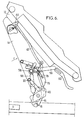
- la figure 6, similaire à la figure 1, montre le siège à l'état basculé.
- Figure 1 shows the elements involved in the invention of a motor vehicle seat, in section along the median longitudinal plane of the seat;
- Figure 2 is a partial view from above, the slides and the part of the seat other than its chassis not being shown;
- Figure 3 is a partial view from the right of Figure 1;
- Figure 4 is an elevational view, on a large scale, showing a slide and the drawer or slide it carries;
- Figure 5 is a half cross-section showing a possible constitution of the slide and the drawer; and
- Figure 6, similar to Figure 1, shows the seat in the tilted state.
Le siège dont les parties concernées par l'invention sont montrées sur les figures comporte une assise sur laquelle un dossier (non-représenté) est fixé de façon à pouvoir tourner autour d'un axe entre une position d'utilisation et une position où il est rabattu sur l'assise. Le châssis d'assise représenté comporte des longerons 10 reliés par des traverses 12. Aux traverses sont fixés deux flasques latéraux 14.The seat whose parts concerned by the invention are shown in the figures comprises a seat on which a backrest (not shown) is fixed so as to be able to rotate about an axis between a position of use and a position where it is folded down on the seat. The seat frame shown has
Les pieds avant 16 du mode de réalisation représenté sont constitués par des parties en saillie des flasques 14. Ces pieds ont une forme terminale en fourche leur permettant de reposer sur des anneaux transversaux 18 servant également au verrouillage du siège. Les pieds arrière 20 sont prévus pour reposer sur des anneaux 22 parallèles aux anneaux 18. Ils sont portés par les flasques 14 de façon à pouvoir tourner autour d'axes respectifs 24 alignés entre la position d'utilisation du siège, fixée par des butées 25, où ils sont montrés en figure 1 et une position rétractée, lorsque le siège est basculé. Le passage de la position normale de la figure 1 à la position rétractée est provoquée automatiquement, lors du basculement, par l'action d'une tringlerie qui sera décrite plus loin.The
Chacun des pieds est muni d'un verrou interdisant normalement le dégagement du pied. Les verrous 26 des pieds avant tournent sur des axes 28 fixés aux flasques. Ils sont simultanément désarmables manuellement par traction sur une manette 30 placée sous l'assise. Un ressort non-représenté tend à les ramener en position active.Each of the feet is provided with a lock normally prohibiting the release of the foot. The
Les verrous arrière 32 tournent, eux, sur des axes 34 portés par les pieds arrières 20. Des ressorts 36 prenant appui sur une barrette 38 tendent à les ramener en position active. Ces verrous sont également désarmables par action sur des moyens qui peuvent avoir diverses constitutions. Dans le cas illustré sur la figure 1, ils comprennent une sangle 39 dont une extrémité est fixée à un palonnier 75 soudé à des manettes 74 placées de part et d'autre du siège. Cette sangle passe sur le palonnier 46 fixé aux pieds, puis sur la barrette 38 à laquelle elle est fixée ; elle se termine par une boucle de traction.The
La tringlerie destinée à escamoter les pieds arrières lors du basculement comporte, dans le mode de réalisation illustré, un ou des leviers 40 dont un bras prend appui sur le plancher, directement ou par l'intermédiaire d'une glissière. L'autre bras est relié par une biellette 42 à une patte 44 d'entraînement en rotation des pieds arrière reliés par un palonnier 46. Un ressort en épingle 71 enroulé autour de l'entretoise 58 et terminé par une roulette 72 exerce sur la biellette 42 une force tendant à la déplacer vers le bas, c'est-à-dire à la rapprocher de l'entretoise, et à repousser les pieds arrière vers la position d'utilisation où ils peuvent s'engager sur leurs anneaux 22.The linkage intended to retract the rear feet during tilting comprises, in the illustrated embodiment, one or
Les anneaux 18 et 22 sont fixés à deux tiroirs 48 déplaçables simultanément dans des glissières 50 fixées au plancher 53 du véhicule (figure 5). La constitution générale de chaque glissière et du tiroir 48 qu'elle contient peut être l'une de celles connues à l'heure actuelle.The
Dans le cas illustré sur les figures 4 et 5, la glissière 50 est en forme de gouttière avec des rebords externes rabattus dans lesquels sont découpées des encoches régulièrement réparties . Elle definit un trajet de circulation du tiroir 48, qui repose sur elle par l'intermédiaire de billes. Les anneaux 18 et 22 sont fixés sur le tiroir par des renforts 51 bloqués à l'aide de vis.In the case illustrated in FIGS. 4 and 5, the
Des moyens de retenue permettent d'immobiliser les tiroirs dans des positions déterminées, réparties à des intervalles réguliers définis par les encoches. Les moyens montrés sur les figures 1, 4 et 5 comportent un verrou 52 pouvant tourner sur le tiroir 48 autour d'un axe 54, repoussé par un ressort 55 vers la position où il est représenté en traits pleins sur la figure 1. Ce verrou comporte des crans 57 prévus pour s'engager dans les encoches de la glissière.Retaining means make it possible to immobilize the drawers in determined positions, distributed at regular intervals defined by the notches. The means shown in FIGS. 1, 4 and 5 comprise a
Des moyens de commande prévus sur le siège, généralement placés de façon à pouvoir être actionnés par l'occupant du siège, permettent de dégager les verrous 52. Dans le mode de réalisation illustré sur la figure, ils comportent un arceau 56 pouvant tourner sur une entretoise transversale 58 et prolongée vers l'avant par une poignée 60 accessible sous l'assise. Les extrémités 62 de l'arceau prennent appui, par l'intermédiaire de vis de réglage 64 (figure 1) sur un actionneur 66 articulé lui aussi autour de l'entretoise 58. Une butée 68 définit la position de repos de la palette 60, vers laquelle elle est ramenée par un ressort 70.Control means provided on the seat, generally placed so that they can be actuated by the occupant of the seat, make it possible to release the
Pour permettre de retourner le siège, le verrou 52 et l'actionneur 66 sont dimensionnés et placés de façon que le point d'appui de l'actionneur sur une palette supérieure du levier se trouve au milieu de l'intervalle défini par les doigts 18 et 22 : ainsi les moyens de commande sont opérationnels dans les deux orientations du siège.To allow the seat to be turned over, the
On décrira maintenant de façon sommaire le mode de mise en action des moyens de déplacement et de repliement du siège représenté.We will now briefly describe the mode of actuation of the means of displacement and folding of the seat shown.
Pour déplacer le siège vers l'avant ou vers l'arrière, il suffit de tirer sur la poignée 60 pour l'amener dans la position représentée en traits mixtes sur la figure 1. L'actionneur 66 tourne et ses parties terminales enfoncent les verrous 52 et libèrent les tiroirs. Le conducteur peut alors déplacer le siège de façon classique. Lorsque l'occupant libère la palette, cette dernière est ramenée par le ressort 70 vers la position de repos, placée de façon à permettre une préhension commode.To move the seat forwards or backwards, it suffices to pull on the
Lorsque l'utilisateur veut faire basculer le siège autour des pieds avant, il désarme les verrous 32. Cette opération peut s'effectuer par traction sur la boucle de la sangle ou si une telle tringlerie de commande est prévue par basculement des manettes 74 placées de part et d'autre de l'assise du siège. Le siège peut alors être basculé dans le sens indiqué par la flèche f sur la figure 6.When the user wants to tilt the seat around the front feet, he disarms the
Une tringlerie destinée à escamoter l'actionneur 66 par pivotement autour de l'entretoise 58 comporte un gousset 76 fixé à la biellette 42, par exemple par soudage. Le gousset 76 est relié par un ressort de traction 78 à un doigt prolongeant une bague 80 (figure 2) montée rotative sur l'entretoise. L'actionneur 66 tourne sur l'entretoise par l'intermédiaire de ses bagues.A linkage intended to retract the
Lorsque l'assise est basculée vers l'avant, le ressort 78 se détend d'abord. Ensuite il entraîne la bague 80 en rotation dans un sens provoquant l'escamotage de l'actionneur 66.When the seat is tilted forward, the
Lorsque l'assise est basculée vers l'arrière pour la ramener en position d'utilisation, le ressort 78 excerce sur l'actionneur 66 une force qui le ramène dans la position où il est montré en traits pleins sur la figure 6, en appui contre les vis de réglage 64.When the seat is tilted back to return it to the position of use, the
Les pieds arrière sont de leur côté escamotés par la poussée exercée par la biellette 42. Au repos, cette biellette, soumise à l'action du ressort 71, maintient les pieds arrière en appui contre les butées 25. Lorsque le siège est basculé vers l'avant, le levier 40 reste en appui sur la glissière et la biellette 42 provoque alors le basculement des pieds arrière dans un sens qui tend à les escamoter entre les flasques.The rear feet are on their side retracted by the thrust exerted by the
Claims (10)
- A seat comprising a base plate having front supports (16) and rear supports (20) which are adapted to bear on transverse fingers or rings (18, 22) supported by the floor and have disengageable latches (26, 32) for attachment to said fingers or rings, characterised in that said fingers or rings (18,22) are attached to a movable element slidably mounted on longitudinal slides (50) attached to the floor, and which movable element comprises means (52) longitudinally retaining said movable element on the slides, said means being disengagable by acting on control means (56, 60) provided on the seat.
- A seat according to Claim 1, characterised in that the control means are formed by a linkage having a loop (56) accessible under the front portion of the base plate and terminating in an actuator (66) acting on the longitudinal retaining means for their disengagement.
- A seat according to Claim 2, characterised in that the point at which the actuator (66) acts on the retaining means is at the centre of the gap between the front and rear fingers (18, 22).
- A seat according to Claims 2 or 3, characterised in that the retaining means are formed by at least one latch (32) which is tiltably mounted on the moving element and is resiliently biased towards a position of engagement in notches in the respective slide.
- A seat according to Claims 2, 3 or 4, characterised in that the movable element comprises two sliders (48) which each slide on a fixed slide.
- A seat according to any of the preceding claims, characterised in that the latch (32) of the rear supports can be manually disengaged independently of the bolts of the front supports.
- A seat according to any of the preceding claims characterised in that it comprises a linkage (40, 42) to automatically rotate the rear supports and/or the control means in a direction which withdraws them at least partially into the space occupied by the base plate during forward tilting and which returns them to the operative position when the base plate returns to its normal position of use.
- A seat according to Claim 7, characterised in that the actuator is formed by a member having collars (80) rotating on the cross strut (66) of the base plate, said linkage comprising at least one lever (40) articulated to a front support (26) and retained bearing against the slide corresponding to the movable elements, while means (76, 42) rotatably mounted on said lever and at least one spring (78) connects a finger, which extends from one of said collars (80), to said rotatably mounted means (76, 42).
- A seat according to Claim 8, characterised in that linkage for automatically rotating the rear supports comprises said rotatably mounted means, which in that case connects said lever (40) to a lug (44) of at least one of the rear supports.
- A seat according to Claims 7 or 8, characterised in that said rotatably mounted means comprise a connecting rod (42), which connects said lever to at least one of the rear supports, and a return spring (71) which exerts a force tending to move the connecting rod towards the strut.
Applications Claiming Priority (2)
| Application Number | Priority Date | Filing Date | Title |
|---|---|---|---|
| FR9300792 | 1993-01-27 | ||
| FR9300792A FR2700735B1 (en) | 1993-01-27 | 1993-01-27 | Removable and adjustable vehicle seat in position. |
Publications (2)
| Publication Number | Publication Date |
|---|---|
| EP0609130A1 EP0609130A1 (en) | 1994-08-03 |
| EP0609130B1 true EP0609130B1 (en) | 1997-03-19 |
Family
ID=9443398
Family Applications (1)
| Application Number | Title | Priority Date | Filing Date |
|---|---|---|---|
| EP94400147A Expired - Lifetime EP0609130B1 (en) | 1993-01-27 | 1994-01-24 | Removable and adjustable vehicle seat |
Country Status (6)
| Country | Link |
|---|---|
| EP (1) | EP0609130B1 (en) |
| AT (1) | ATE150391T1 (en) |
| DE (1) | DE69402089T2 (en) |
| DK (1) | DK0609130T3 (en) |
| ES (1) | ES2100635T3 (en) |
| FR (1) | FR2700735B1 (en) |
Families Citing this family (26)
| Publication number | Priority date | Publication date | Assignee | Title |
|---|---|---|---|---|
| FR2735729B1 (en) * | 1995-06-22 | 1997-08-29 | Irausa Ingeniera | SECURITY FASTENER FOR REMOVABLE VEHICLE SEAT |
| DE19544833C2 (en) | 1995-12-01 | 2001-06-21 | Brose Fahrzeugteile | Device for releasably connecting a vehicle seat to the vehicle floor |
| FR2750658B1 (en) * | 1996-07-03 | 1998-11-06 | Ecia Equip Composants Ind Auto | VARIABLE CONFIGURATION AND EASY HANDLING SEAT FOR MOTOR VEHICLE |
| DE19846031C2 (en) * | 1997-10-08 | 2002-01-17 | Mitsubishi Motors Corp | Detachable folding seat |
| FR2771348B1 (en) | 1997-11-21 | 2000-01-28 | Faure Bertrand Equipements Sa | VEHICLE SEAT ASSEMBLY COMPRISING A REMOVABLE SEAT MOUNTED ON SLIDERS |
| FR2772315B1 (en) * | 1997-12-12 | 2000-03-03 | Peugeot | REMOVABLE SEAT ARRANGEMENT AND LONGITUDINAL POSITION ADJUSTMENT IN A VEHICLE INTERIOR |
| FR2772316B1 (en) * | 1997-12-12 | 2000-03-03 | Peugeot | REMOVABLE AND ADJUSTABLE SEAT ARRANGEMENT IN LONGITUDINAL POSITION IN A MOTOR VEHICLE INTERIOR |
| FR2772686B3 (en) | 1997-12-22 | 2000-02-18 | Faure Bertrand Equipements Sa | SEAT KIT FOR VEHICLE INCLUDING A REMOVABLE SEAT MOUNTED ON SLIDES |
| FR2772685B1 (en) | 1997-12-22 | 2000-02-25 | Faure Bertrand Equipements Sa | VEHICLE SEAT ASSEMBLY COMPRISING A REMOVABLE SEAT MOUNTED ON SLIDERS |
| FR2774045B1 (en) * | 1998-01-27 | 2000-03-10 | Irausa Ingeniera Sa | VEHICLE SEAT, REMOVABLE, TURNABLE AND LONGITUDINALLY ADJUSTABLE |
| DE29804542U1 (en) | 1998-03-13 | 1999-07-15 | Johnson Controls GmbH, 51399 Burscheid | Device for holding a vehicle seat |
| FR2776580B1 (en) * | 1998-03-25 | 2000-04-21 | Peugeot | REMOVABLE AND ADJUSTABLE SEAT ARRANGEMENT IN LONGITUDINAL POSITION IN A MOTOR VEHICLE INTERIOR |
| FR2776970B1 (en) * | 1998-04-03 | 2000-06-16 | Faure Bertrand Equipements Sa | VEHICLE SEAT ASSEMBLY COMPRISING A REMOVABLE SEAT MOUNTED ON SLIDERS |
| DE19820093C2 (en) * | 1998-05-06 | 2000-03-09 | Faure Bertrand Sitztech Gmbh | Foot for an automobile seat |
| DE29808871U1 (en) | 1998-05-16 | 1999-09-30 | Johnson Controls GmbH, 51399 Burscheid | Device for holding a vehicle seat |
| FR2779685B1 (en) * | 1998-06-10 | 2000-08-04 | Peugeot | ADJUSTABLE AND REMOVABLE SEAT ARRANGEMENT IN A MOTOR VEHICLE INTERIOR |
| FR2779686B1 (en) * | 1998-06-10 | 2000-07-21 | Peugeot | ADJUSTABLE AND REMOVABLE SEAT ARRANGEMENT IN A MOTOR VEHICLE INTERIOR |
| FR2781732B1 (en) * | 1998-07-31 | 2000-10-06 | Irausa Ingeniera Sa | VEHICLE SEAT, REMOVABLE, TURNABLE AND LONGITUDINALLY ADJUSTABLE BY CONTROLS ON ITS SLIDES |
| MXPA01003166A (en) * | 1998-10-09 | 2003-05-15 | Magna Seating Sys Inc | Automated fold and tumble vehicle seat assembly. |
| FR2790236B1 (en) | 1999-02-25 | 2001-05-18 | Faure Bertrand Equipements Sa | SLIDER FOR REMOVABLE VEHICLE SEAT |
| FR2791619B1 (en) | 1999-04-02 | 2001-06-15 | Matra Automobile | FOLDABLE SEAT IN ARMREST FOR VEHICLE PASSENGER |
| FR2791616B1 (en) * | 1999-04-02 | 2001-06-29 | Matra Automobile | RETRACTABLE SEAT BY FOLDING FOR VEHICLE PASSENGER |
| FR2793454B1 (en) | 1999-05-14 | 2001-07-27 | Faure Bertrand Equipements Sa | VEHICLE SEAT ASSEMBLY |
| FR2796344B1 (en) * | 1999-07-15 | 2001-08-03 | Peugeot Citroen Automobiles Sa | ANCHORAGE AND ARTICULATION MECHANISM, IN PARTICULAR FOR A REAR SEAT OF A MOTOR VEHICLE |
| FR2833544B1 (en) * | 2001-12-18 | 2004-02-13 | Renault | BASE FOR MOTOR VEHICLE SEAT AND MOTOR SEAT PROVIDED WITH SUCH A BASE |
| FR2857634B1 (en) * | 2003-07-18 | 2006-11-10 | Gruau Laval | DEVICE FOR LONGITUDINAL ADJUSTMENT AND LOCKING IN PREDETERMINED POSITION OF A VEHICLE EQUIPMENT |
Family Cites Families (5)
| Publication number | Priority date | Publication date | Assignee | Title |
|---|---|---|---|---|
| DE2753307A1 (en) * | 1977-11-30 | 1979-05-31 | Hammerstein Gmbh C Rob | HEIGHT AND TILT ADJUSTMENT DEVICE FOR VEHICLE SEATS |
| FR2556946B1 (en) * | 1983-10-25 | 1986-12-12 | Sable | MOBILE SEAT, IN PARTICULAR REMOVABLE SEAT FOR VEHICLE |
| US4723732A (en) * | 1985-09-12 | 1988-02-09 | The Boeing Company | Movable seating system for aircraft |
| FR2611616B1 (en) * | 1987-03-04 | 1990-06-15 | Peugeot | ARRANGEMENT OF A SEAT ON THE FLOOR OF A MOTOR VEHICLE |
| FR2673148B1 (en) * | 1991-02-21 | 1993-05-07 | Peugeot | REMOVABLE VEHICLE SEAT. |
-
1993
- 1993-01-27 FR FR9300792A patent/FR2700735B1/en not_active Expired - Fee Related
-
1994
- 1994-01-24 ES ES94400147T patent/ES2100635T3/en not_active Expired - Lifetime
- 1994-01-24 AT AT94400147T patent/ATE150391T1/en not_active IP Right Cessation
- 1994-01-24 DE DE69402089T patent/DE69402089T2/en not_active Expired - Lifetime
- 1994-01-24 DK DK94400147.8T patent/DK0609130T3/en active
- 1994-01-24 EP EP94400147A patent/EP0609130B1/en not_active Expired - Lifetime
Also Published As
| Publication number | Publication date |
|---|---|
| ATE150391T1 (en) | 1997-04-15 |
| EP0609130A1 (en) | 1994-08-03 |
| FR2700735A1 (en) | 1994-07-29 |
| ES2100635T3 (en) | 1997-06-16 |
| DK0609130T3 (en) | 1997-09-08 |
| DE69402089T2 (en) | 1997-08-07 |
| FR2700735B1 (en) | 1995-04-07 |
| DE69402089D1 (en) | 1997-04-24 |
Similar Documents
| Publication | Publication Date | Title |
|---|---|---|
| EP0609130B1 (en) | Removable and adjustable vehicle seat | |
| CA2460630C (en) | Automobile seat rail | |
| EP0931689B1 (en) | Vehicle seat, removable, reversible and longitudinally adjustable | |
| FR2589800A1 (en) | TRANSFORMABLE REAR SEAT | |
| FR2787398A1 (en) | SEAT DEVICE FOR A VEHICLE | |
| FR2843721A1 (en) | Seat, in particular removable seat of mini van with several rows of seats, comprising folding mechanism working only in pre-determined position | |
| FR2917679A1 (en) | RECOVERABLE SEAT, IN PARTICULAR FOR A MOTOR VEHICLE | |
| WO2010010274A1 (en) | Vehicle seat | |
| FR2721866A1 (en) | MECHANISM FOR SLIDING A VEHICLE SEAT | |
| EP0800952B1 (en) | Forwardly displaceable automotive vehicle seat, to access the rear space | |
| FR2833545A1 (en) | MOUNTING SYSTEM AND SEAT ASSEMBLY PROVIDED WITH SUCH A SYSTEM | |
| FR2634699A1 (en) | Device forming a seat slideway | |
| EP0047699A1 (en) | Tiltable seat with foldable seat back for a vehicle | |
| FR2527060A1 (en) | SEAT ASSEMBLY ADJUSTABLE TO TWO INDEPENDENT CONTROL MECHANISMS | |
| EP0402195B1 (en) | Demountable fastening device for the rear seat of a motor vehicle | |
| EP0404628B1 (en) | Seat with an adjustable and tiltable backrest | |
| FR2527062A1 (en) | ADJUSTABLE SEAT ASSEMBLY | |
| FR2780003A1 (en) | ADJUSTABLE REAR SEAT IN LONGITUDINAL POSITION IN A MOTOR VEHICLE INTERIOR | |
| FR3034723A1 (en) | REAR BENCH LOCK DEVICE | |
| FR2631004A1 (en) | Support column for receiving articles resting on catches which can be locked in an active position | |
| FR2776588A1 (en) | Fold down seat back for rear seat of vehicle, | |
| FR2609948A1 (en) | INERTIAL LOCKING DEVICE FOR VEHICLE SEAT | |
| FR2785579A1 (en) | Seat fittings, for vehicle, designed to allow seat to be released from locked position by control lever, which also acts to raise seat and to displace the seat relative to vehicle floor | |
| FR2779686A1 (en) | Vehicle seat fittings for adjustable seat positioning | |
| WO2016030639A1 (en) | Seat for a vehicle having a load floor |
Legal Events
| Date | Code | Title | Description |
|---|---|---|---|
| PUAI | Public reference made under article 153(3) epc to a published international application that has entered the european phase |
Free format text: ORIGINAL CODE: 0009012 |
|
| AK | Designated contracting states |
Kind code of ref document: A1 Designated state(s): AT CH DE DK ES GB IT LI NL PT SE |
|
| 17P | Request for examination filed |
Effective date: 19941008 |
|
| 17Q | First examination report despatched |
Effective date: 19951218 |
|
| GRAG | Despatch of communication of intention to grant |
Free format text: ORIGINAL CODE: EPIDOS AGRA |
|
| GRAH | Despatch of communication of intention to grant a patent |
Free format text: ORIGINAL CODE: EPIDOS IGRA |
|
| GRAH | Despatch of communication of intention to grant a patent |
Free format text: ORIGINAL CODE: EPIDOS IGRA |
|
| GRAA | (expected) grant |
Free format text: ORIGINAL CODE: 0009210 |
|
| AK | Designated contracting states |
Kind code of ref document: B1 Designated state(s): AT CH DE DK ES GB IT LI NL PT SE |
|
| REF | Corresponds to: |
Ref document number: 150391 Country of ref document: AT Date of ref document: 19970415 Kind code of ref document: T |
|
| REG | Reference to a national code |
Ref country code: CH Ref legal event code: EP |
|
| REF | Corresponds to: |
Ref document number: 69402089 Country of ref document: DE Date of ref document: 19970424 |
|
| REG | Reference to a national code |
Ref country code: CH Ref legal event code: NV Representative=s name: KELLER & PARTNER PATENTANWAELTE AG |
|
| GBT | Gb: translation of ep patent filed (gb section 77(6)(a)/1977) |
Effective date: 19970416 |
|
| ITF | It: translation for a ep patent filed | ||
| REG | Reference to a national code |
Ref country code: ES Ref legal event code: FG2A Ref document number: 2100635 Country of ref document: ES Kind code of ref document: T3 |
|
| REG | Reference to a national code |
Ref country code: PT Ref legal event code: SC4A Free format text: AVAILABILITY OF NATIONAL TRANSLATION Effective date: 19970429 |
|
| REG | Reference to a national code |
Ref country code: DK Ref legal event code: T3 |
|
| PLBE | No opposition filed within time limit |
Free format text: ORIGINAL CODE: 0009261 |
|
| STAA | Information on the status of an ep patent application or granted ep patent |
Free format text: STATUS: NO OPPOSITION FILED WITHIN TIME LIMIT |
|
| 26N | No opposition filed | ||
| REG | Reference to a national code |
Ref country code: GB Ref legal event code: IF02 |
|
| PGFP | Annual fee paid to national office [announced via postgrant information from national office to epo] |
Ref country code: NL Payment date: 20100716 Year of fee payment: 17 Ref country code: ES Payment date: 20100728 Year of fee payment: 17 Ref country code: CH Payment date: 20100716 Year of fee payment: 17 |
|
| PGFP | Annual fee paid to national office [announced via postgrant information from national office to epo] |
Ref country code: SE Payment date: 20100716 Year of fee payment: 17 Ref country code: IT Payment date: 20100724 Year of fee payment: 17 Ref country code: DE Payment date: 20100726 Year of fee payment: 17 Ref country code: AT Payment date: 20100721 Year of fee payment: 17 |
|
| PGFP | Annual fee paid to national office [announced via postgrant information from national office to epo] |
Ref country code: GB Payment date: 20100716 Year of fee payment: 17 |
|
| PGFP | Annual fee paid to national office [announced via postgrant information from national office to epo] |
Ref country code: PT Payment date: 20100721 Year of fee payment: 17 Ref country code: DK Payment date: 20100723 Year of fee payment: 17 |
|
| REG | Reference to a national code |
Ref country code: PT Ref legal event code: MM4A Free format text: LAPSE DUE TO NON-PAYMENT OF FEES Effective date: 20110725 |
|
| REG | Reference to a national code |
Ref country code: NL Ref legal event code: V1 Effective date: 20110801 |
|
| REG | Reference to a national code |
Ref country code: DK Ref legal event code: EBP |
|
| REG | Reference to a national code |
Ref country code: CH Ref legal event code: PL |
|
| REG | Reference to a national code |
Ref country code: SE Ref legal event code: EUG |
|
| GBPC | Gb: european patent ceased through non-payment of renewal fee |
Effective date: 20110124 |
|
| PG25 | Lapsed in a contracting state [announced via postgrant information from national office to epo] |
Ref country code: LI Free format text: LAPSE BECAUSE OF NON-PAYMENT OF DUE FEES Effective date: 20110131 Ref country code: PT Free format text: LAPSE BECAUSE OF NON-PAYMENT OF DUE FEES Effective date: 20110725 Ref country code: CH Free format text: LAPSE BECAUSE OF NON-PAYMENT OF DUE FEES Effective date: 20110131 |
|
| PG25 | Lapsed in a contracting state [announced via postgrant information from national office to epo] |
Ref country code: AT Free format text: LAPSE BECAUSE OF NON-PAYMENT OF DUE FEES Effective date: 20110124 Ref country code: GB Free format text: LAPSE BECAUSE OF NON-PAYMENT OF DUE FEES Effective date: 20110124 |
|
| REG | Reference to a national code |
Ref country code: DE Ref legal event code: R119 Ref document number: 69402089 Country of ref document: DE Effective date: 20110802 |
|
| PG25 | Lapsed in a contracting state [announced via postgrant information from national office to epo] |
Ref country code: IT Free format text: LAPSE BECAUSE OF NON-PAYMENT OF DUE FEES Effective date: 20110124 Ref country code: NL Free format text: LAPSE BECAUSE OF NON-PAYMENT OF DUE FEES Effective date: 20110801 |
|
| REG | Reference to a national code |
Ref country code: ES Ref legal event code: FD2A Effective date: 20120220 |
|
| PG25 | Lapsed in a contracting state [announced via postgrant information from national office to epo] |
Ref country code: ES Free format text: LAPSE BECAUSE OF NON-PAYMENT OF DUE FEES Effective date: 20110125 |
|
| PG25 | Lapsed in a contracting state [announced via postgrant information from national office to epo] |
Ref country code: SE Free format text: LAPSE BECAUSE OF NON-PAYMENT OF DUE FEES Effective date: 20110125 |
|
| PG25 | Lapsed in a contracting state [announced via postgrant information from national office to epo] |
Ref country code: DE Free format text: LAPSE BECAUSE OF NON-PAYMENT OF DUE FEES Effective date: 20110802 |