EP0608992A1 - Dual purpose, low profile antenna - Google Patents
Dual purpose, low profile antenna Download PDFInfo
- Publication number
- EP0608992A1 EP0608992A1 EP94300294A EP94300294A EP0608992A1 EP 0608992 A1 EP0608992 A1 EP 0608992A1 EP 94300294 A EP94300294 A EP 94300294A EP 94300294 A EP94300294 A EP 94300294A EP 0608992 A1 EP0608992 A1 EP 0608992A1
- Authority
- EP
- European Patent Office
- Prior art keywords
- antenna
- signals
- high frequency
- antenna according
- low frequency
- Prior art date
- Legal status (The legal status is an assumption and is not a legal conclusion. Google has not performed a legal analysis and makes no representation as to the accuracy of the status listed.)
- Withdrawn
Links
Images

Classifications
-
- H—ELECTRICITY
- H01—ELECTRIC ELEMENTS
- H01Q—ANTENNAS, i.e. RADIO AERIALS
- H01Q1/00—Details of, or arrangements associated with, antennas
- H01Q1/27—Adaptation for use in or on movable bodies
- H01Q1/32—Adaptation for use in or on road or rail vehicles
- H01Q1/325—Adaptation for use in or on road or rail vehicles characterised by the location of the antenna on the vehicle
- H01Q1/3275—Adaptation for use in or on road or rail vehicles characterised by the location of the antenna on the vehicle mounted on a horizontal surface of the vehicle, e.g. on roof, hood, trunk
-
- H—ELECTRICITY
- H01—ELECTRIC ELEMENTS
- H01Q—ANTENNAS, i.e. RADIO AERIALS
- H01Q5/00—Arrangements for simultaneous operation of antennas on two or more different wavebands, e.g. dual-band or multi-band arrangements
- H01Q5/40—Imbricated or interleaved structures; Combined or electromagnetically coupled arrangements, e.g. comprising two or more non-connected fed radiating elements
-
- H—ELECTRICITY
- H01—ELECTRIC ELEMENTS
- H01Q—ANTENNAS, i.e. RADIO AERIALS
- H01Q9/00—Electrically-short antennas having dimensions not more than twice the operating wavelength and consisting of conductive active radiating elements
- H01Q9/04—Resonant antennas
- H01Q9/0407—Substantially flat resonant element parallel to ground plane, e.g. patch antenna
- H01Q9/0464—Annular ring patch
-
- H—ELECTRICITY
- H01—ELECTRIC ELEMENTS
- H01Q—ANTENNAS, i.e. RADIO AERIALS
- H01Q9/00—Electrically-short antennas having dimensions not more than twice the operating wavelength and consisting of conductive active radiating elements
- H01Q9/04—Resonant antennas
- H01Q9/30—Resonant antennas with feed to end of elongated active element, e.g. unipole
- H01Q9/32—Vertical arrangement of element
- H01Q9/36—Vertical arrangement of element with top loading
Definitions
- the present invention relates to a dual purpose antenna, that is an antenna which is capable of operating with signals in widely separated parts of the radio spectrum simultaneously, and in particular to a dual purpose antenna which has a low physical profile.
- an antenna is designed to operate in a relatively restricted region of the radio spectrum and is optimised for operation in that region.
- a mobile location unit In addition to monitoring the position of a mobile for reporting back to a base station it has also been proposed to make use of a mobile location unit for other purposes.
- optimum values of various operating parameters of the transceiver depend on its position and a MLU may be used to adapt or condition the operation of the transceiver according to its calculated position.
- the calculated location may also be used to adapt or condition the operation of a mobile's cellular radio transceiver to local characteristics of the cellular radio network, for example what transmitter power and which frequency channels to use. (see our British Patent No 87/11490 "Mobile Transmitter/Receiver").
- the wavelengths of radio waves at the frequencies used in applications such as cellular radio and the data transmissions used in systems such as Datatrak on the one hand and low frequency mobile location systems on the other differ by several orders of magnitude making it difficult to design a single antenna which is usable with both.
- the present invention provides a dual purpose antenna usable with radio signals in two widely separated regions of the radio spectrum simultaneously and which comprise high frequency and low frequency sections usable with signals in the higher and lower of the two regions respectively, the high and low frequency sections being integrated into an antenna assembly which comprises an antenna arrangement tuned and loaded for operation in the high frequency region and a voltage probe for receiving the E-component of signals in the low frequency region.
- the antenna arrangement may include a number of antenna elements, one of which serves also as the voltage probe.
- it may comprise first and second planar conductive antenna elements separated by a dielectric, the first element being a radiating/receiving element for the high frequency signals and the second element serving both as part of a resonant circuit including the first element in its high frequency operation and as the LF voltage probe.
- the HF section may have a third, linear radiating element whose axis extends out of the plane of the first and second elements from the centre of the first element, whereby the antenna acts to radiate signals in the high frequency region omnidirectionally, the radiated signals being polarised in the direction of the axis of the third element.
- Using a voltage probe to pick up the E-component (electric component) of the low frequency signal frees the antenna from having its dimensions constrained by the wavelength of the low frequency signals.
- the present invention permits a dual purpose antenna to be produced which is physically compact and of a low profile which is convenient in itself and enables the antenna to be packaged in an enclosure which is resistant to tampering, (e.g. by someone attempting to disable communication from the mobile), while permitting a single-point fixing to the roof of a vehicle or other moving object.
- the antenna elements are disposed as two electively conductive areas of metal foil on a dielectric substrate, with the first element being in the form of a circular disk which is concentric with and spaced from the second element which takes the form of a circular annulus.
- Figure 1 shows a horizontal section through one embodiment of the invention for use in transmitting and receiving high frequency signals in the UHF region (e.g 460 MHz) as used in the Datatrak system for data transmission, while simultaneously receiving location signals transmitted by the Datatrak system which operates on a frequency of 140 KHz.
- the wavelengths involved are therefore of the order of 65 cms for the UHF signals and 2.1 km metres for the low frequency ones.
- the UHF section transmits omnidirectional, vertically polarised UHF signals.
- the antenna assembly is wholly contained within a weather- and tamper-proof housing 2 comprising a circular metal baseplate 3 and a cover 4 of tough plastics material.
- a seal 5 in the form of an inverted U located in a groove in the underside of the cover 4 surrounds and seals against the upturned peripheral rim of the baseplate 3 to render the housing watertight.
- the baseplate 3 serves as a ground plane for the antenna circuitry.
- a circular disk shaped element 6 manufactured as a printed circuit board is mounted above and parallel to the baseplate 3 by a number of angularly spaced stand-offs or mounting pillars around its periphery, and one at its centre.
- the disk 6 comprises a circular substrate of dielectric material having antenna elements 7 and 8 on it in the form of two concentric metal (copper) foil layers laid out as shown in figure 2.
- a rectangular printed circuit board 9 is mounted to the base plate 3 by means of stand offs so as to be located below the centre of the antenna element 7.
- a linear vertical UHF radiating element 10 in the form of a rod shaped metal support pillar extends upwardly from the centre of the PCB 9 and is electrically connected to the radiating element 7 by a screw through the centre of disk 6.
- the circuit board 9 also has on it circuitry, described below, to couple the elements 7 and 8 to a coaxial cable fed through a single point fixing collar 30 of the antenna to the roof of the mobile so the antenna can be installed by drilling a single hole in the roof of a vehicle.
- the lower part of the periphery of the fixing is threaded to take a fixing nut.
- the cable is fitted with a BNC connector 11 at its end for connection to the equipment within the vehicle.
- the interior of the antenna housing is open to the interior of the vehicle via the collar 30. This enables the housing to "breath" when subject to temperature changes, which avoids stressing the seal to the mounting plate 3 and the ingress of water when a partial vacuum develops within the housing.
- the antenna is designed to receive 'E' field LF signals and transmit omnidirectional, vertically polarised UHF signals.
- the UHF radiating section is made up of the elements 7 and 8 on the disk 6 (which is 12cm in diameter) and the vertical mounting pillar 10 which is relatively short (3cm). It will be appreciated from Figure 1, which shows these elements to scale in relation to the remainder of the antenna, that the antenna is very compact. The dimensions allow the complete assembly to have a low profile, which is desirable for security applications and for tall vehicles. The simple construction also means the antenna is cheap to manufacture and easy to install because of the single hole mounting.
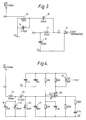
- Figure 3 shows the components on the PCB 9 associated with the UHF section of the antenna and also the diplexer 12 which couples the UHF and LF sections to the coaxial termination within the coaxial connector 11. Reducing the length of the vertical radiating element 10 to the size mentioned above results in reduced coupling of the power in the antenna to the ether. This results in a decrease in resistance of the radiating element 10 to around 10 ohms (compared to 50 ohms for a full 1 ⁇ 4 wave element).
- the antenna element 10 is connected to the centre top of a 12nH conductor 13 formed as a track on the PCB 9. Inductor 13 and adjustable capacitor 14 form a parallel tuned circuit.
- the antenna element 8 serves as the voltage probe for E-components of the LF signal.
- the PCB 9 has on it a low noise LF amplifier 18, shown in Figure 4 which is powered by a DC supply fed to it across the conductors of the coaxial connector 11. All bar one of the support pillars which support the periphery of the disk 6 are made of electrically insulating material. The remaining one is metal and connects the antenna element 8 to the input of the amplifier 18 via a lead.
- the LF voltage input to amplifier 18 is passed through the inductor 13, a double tuned circuit formed of capacitors 19 and 20 and inductors 22 and 23, to reject out of band signals, and to allow the stray reactances in the voltage probe to be tuned out.
- the impedance of the tuned circuit should be made as high as practically possible to ensure a reasonable match to the (very high impedance) probe. This results in maximum signal voltage appearing at the lower gate of dual insulated gate FET 24 which, with the remainder of the components shown in Figure 4, functions as a high input impedance cascode amplifier.
- the output of the amplifier at J2 from the tap on inductor 25 is taken to the feeder via the diplexer circuit 12 in Figure 3.
- the remote end of the coaxial feeder from connector 11 is connected to a UHF transceiver, the mobile location unit and a DC power source for the amplifier 18.
- the embodiment described above illustrates the application of the invention to use with the location and data transmission signals of the Datatrak system, it will be apparent that the invention may be applied to an antenna for other signals, e.g. where the HF signal is a UHF cellular radio signal.
Abstract
Description
- The present invention relates to a dual purpose antenna, that is an antenna which is capable of operating with signals in widely separated parts of the radio spectrum simultaneously, and in particular to a dual purpose antenna which has a low physical profile.
- Generally speaking, an antenna is designed to operate in a relatively restricted region of the radio spectrum and is optimised for operation in that region.
- Recent work in the field of mobile communications has led to a requirement for radio operation in widely separated regions of the radio spectrum. In mobile cellular radio systems, mobile transceivers communicate with one another via a network of fixed base stations using signals in the UHF part of the spectrum. On the other hand, mobile location systems such as Datatrak (RTM) use signals from static locator beacons transmitted at very low frequencies to enable equipment (known as a mobile location unit or MLU) on a vehicle or other moving object to determine its location for any of a number of purposes, and the location determined by the MLU is reported to a base station via a UHF transmission from the mobile for purposes such as monitoring the position of the mobile.
- In addition to monitoring the position of a mobile for reporting back to a base station it has also been proposed to make use of a mobile location unit for other purposes. For example, in the case of a mobile equipped with a cellular radio transceiver, optimum values of various operating parameters of the transceiver depend on its position and a MLU may be used to adapt or condition the operation of the transceiver according to its calculated position. For example the calculated location may also be used to adapt or condition the operation of a mobile's cellular radio transceiver to local characteristics of the cellular radio network, for example what transmitter power and which frequency channels to use. (see our British Patent No 87/11490 "Mobile Transmitter/Receiver").
- The wavelengths of radio waves at the frequencies used in applications such as cellular radio and the data transmissions used in systems such as Datatrak on the one hand and low frequency mobile location systems on the other differ by several orders of magnitude making it difficult to design a single antenna which is usable with both.
- The present invention provides a dual purpose antenna usable with radio signals in two widely separated regions of the radio spectrum simultaneously and which comprise high frequency and low frequency sections usable with signals in the higher and lower of the two regions respectively, the high and low frequency sections being integrated into an antenna assembly which comprises an antenna arrangement tuned and loaded for operation in the high frequency region and a voltage probe for receiving the E-component of signals in the low frequency region.
- The antenna arrangement may include a number of antenna elements, one of which serves also as the voltage probe.
- In particular, it may comprise first and second planar conductive antenna elements separated by a dielectric, the first element being a radiating/receiving element for the high frequency signals and the second element serving both as part of a resonant circuit including the first element in its high frequency operation and as the LF voltage probe.
- The HF section may have a third, linear radiating element whose axis extends out of the plane of the first and second elements from the centre of the first element, whereby the antenna acts to radiate signals in the high frequency region omnidirectionally, the radiated signals being polarised in the direction of the axis of the third element.
- Using a voltage probe to pick up the E-component (electric component) of the low frequency signal frees the antenna from having its dimensions constrained by the wavelength of the low frequency signals.
- As will become apparent from the following description, the present invention permits a dual purpose antenna to be produced which is physically compact and of a low profile which is convenient in itself and enables the antenna to be packaged in an enclosure which is resistant to tampering, (e.g. by someone attempting to disable communication from the mobile), while permitting a single-point fixing to the roof of a vehicle or other moving object.
- In one particularly convenient form, the antenna elements are disposed as two electively conductive areas of metal foil on a dielectric substrate, with the first element being in the form of a circular disk which is concentric with and spaced from the second element which takes the form of a circular annulus.
- The invention will be further described by way of non-limitative example with reference to the accompanying drawings, in which:-
- Figure 1 is a horizontal diametral cross section of an antenna embodying the present invention;
- Figure 2 illustrates schematically the layout of the first and second radiator elements of the antenna of Figure 1;
- Figure 3 shows the circuitry associated with the HF section and diplexer of the antenna of Figure 1; and
- Figure 4 shows the circuitry associated with the LF section of the antenna of Figure 1.
- Figure 1 shows a horizontal section through one embodiment of the invention for use in transmitting and receiving high frequency signals in the UHF region (e.g 460 MHz) as used in the Datatrak system for data transmission, while simultaneously receiving location signals transmitted by the Datatrak system which operates on a frequency of 140 KHz. The wavelengths involved are therefore of the order of 65 cms for the UHF signals and 2.1 km metres for the low frequency ones. The UHF section transmits omnidirectional, vertically polarised UHF signals.
- The antenna assembly, generally designated 1, is wholly contained within a weather- and tamper-
proof housing 2 comprising acircular metal baseplate 3 and acover 4 of tough plastics material. Aseal 5 in the form of an inverted U located in a groove in the underside of thecover 4 surrounds and seals against the upturned peripheral rim of thebaseplate 3 to render the housing watertight. Thebaseplate 3 serves as a ground plane for the antenna circuitry. - Within the housing a circular disk
shaped element 6 manufactured as a printed circuit board is mounted above and parallel to thebaseplate 3 by a number of angularly spaced stand-offs or mounting pillars around its periphery, and one at its centre. - The
disk 6 comprises a circular substrate of dielectric material havingantenna elements - A rectangular printed
circuit board 9 is mounted to thebase plate 3 by means of stand offs so as to be located below the centre of theantenna element 7. A linear vertical UHFradiating element 10 in the form of a rod shaped metal support pillar extends upwardly from the centre of thePCB 9 and is electrically connected to theradiating element 7 by a screw through the centre ofdisk 6. Thecircuit board 9 also has on it circuitry, described below, to couple theelements point fixing collar 30 of the antenna to the roof of the mobile so the antenna can be installed by drilling a single hole in the roof of a vehicle. The lower part of the periphery of the fixing is threaded to take a fixing nut. The cable is fitted with aBNC connector 11 at its end for connection to the equipment within the vehicle. - The interior of the antenna housing is open to the interior of the vehicle via the
collar 30. This enables the housing to "breath" when subject to temperature changes, which avoids stressing the seal to themounting plate 3 and the ingress of water when a partial vacuum develops within the housing. - As described above, the antenna is designed to receive 'E' field LF signals and transmit omnidirectional, vertically polarised UHF signals. The UHF radiating section is made up of the
elements vertical mounting pillar 10 which is relatively short (3cm). It will be appreciated from Figure 1, which shows these elements to scale in relation to the remainder of the antenna, that the antenna is very compact. The dimensions allow the complete assembly to have a low profile, which is desirable for security applications and for tall vehicles. The simple construction also means the antenna is cheap to manufacture and easy to install because of the single hole mounting. - As the central
UHF radiating element 10 is shorter than ¼ wave at the UHF transmit frequency, capacitive loading is required to achieve resonance. This loading is mainly provided by theinner disc 7 of thedisk 6 mounted on top of the vertical UHF radiating element, although as theouter ring element 8 is isolated at UHF frequencies, capacitive coupling between theinner disc element 7 andouter ring element 8 means that thewhole disk 6 is involved in defining the frequency of resonance of the assembly. - Figure 3 shows the components on the
PCB 9 associated with the UHF section of the antenna and also the diplexer 12 which couples the UHF and LF sections to the coaxial termination within thecoaxial connector 11. Reducing the length of the vertical radiatingelement 10 to the size mentioned above results in reduced coupling of the power in the antenna to the ether. This results in a decrease in resistance of theradiating element 10 to around 10 ohms (compared to 50 ohms for a full ¼ wave element). Theantenna element 10 is connected to the centre top of a12nH conductor 13 formed as a track on thePCB 9.Inductor 13 andadjustable capacitor 14 form a parallel tuned circuit. Driving the radiating element from the tap oninductor 13 provides impedance matching to the 50 ohm output of the UHF transmitter.Capacitors inductor 17 work as a diplexer, allowing the UHF signal to share the same feeder as the received LF signals. - In addition to assisting in the loading of the UHF section, the
antenna element 8 serves as the voltage probe for E-components of the LF signal. To reduce interference and noise, thePCB 9 has on it a low noise LF amplifier 18, shown in Figure 4 which is powered by a DC supply fed to it across the conductors of thecoaxial connector 11. All bar one of the support pillars which support the periphery of thedisk 6 are made of electrically insulating material. The remaining one is metal and connects theantenna element 8 to the input of the amplifier 18 via a lead. The LF voltage input to amplifier 18 is passed through theinductor 13, a double tuned circuit formed ofcapacitors inductors gate FET 24 which, with the remainder of the components shown in Figure 4, functions as a high input impedance cascode amplifier. The output of the amplifier at J2 from the tap oninductor 25 is taken to the feeder via the diplexer circuit 12 in Figure 3. - The remote end of the coaxial feeder from
connector 11 is connected to a UHF transceiver, the mobile location unit and a DC power source for the amplifier 18. - Although the embodiment described above illustrates the application of the invention to use with the location and data transmission signals of the Datatrak system, it will be apparent that the invention may be applied to an antenna for other signals, e.g. where the HF signal is a UHF cellular radio signal.
Claims (12)
- A dual purpose antenna usable with radio signals in two widely separated regions of the radio spectrum simultaneously and which comprise high frequency and low frequency sections usable with signals in the higher and lower of the two regions respectively, the high and low frequency sections being integrated into an antenna assembly which comprises an antenna arrangement (6,7,8,10) tuned and loaded for operation in the high frequency region and a voltage probe (8) for receiving the E-component of signals in the low frequency region.
- An antenna according to claim 1 wherein the antenna arrangement includes a number of antenna elements, one of which serves also as the voltage probe.
- An antenna according to claim 1 or 2 wherein the arrangement of antenna elements comprises first (7) and second (8) planar conductive antenna elements separated by a dielectric, the first element (7) being a radiating/receiving element for the high frequency signals and the second element (8) serving both as part of a resonant circuit including the first element in its high frequency operation and as the LF voltage probe.
- An antenna according to claim 3 wherein the first and second antenna elements (7,8) are disposed as two electrically conductive areas of metal foil on a dielectric substrate, with the first (7) element being surrounded by the second element (8).
- An antenna according to claim 4 wherein the dielectric substrate is in the form of a disk (6), the first element (7) is circular and concentric with the disc and the second element (8) is a circular annulus concentric with the first element (7).
- An antenna according to any one of claims 3 to 5 and including a third, linear antenna element (10) whose axis extends out of the plane of the first and second elements (7,8) from the centre of the first element (7), whereby the antenna acts to radiate signals in the high frequency region omnidirectionally, the radiated signals being polarised in the direction of the axis of the third element (10).
- An antenna according to claim 6 wherein the length of the third antenna element (10) is less than ¼ the wavelength of signals in the high frequency region.
- An antenna according to any one of the preceding claims and having integrated therein circuitry (9,13-25) for coupling the high frequency and low frequency signals to external equipment via a shared pair of conductors and for amplifying and bandwidth limiting the low frequency signals from the second antenna acting as a low frequency voltage probe.
- An antenna according to claim 6 and claim 7 or 8 wherein the third antenna element (10) is an electrically conductive support pillar extending between the first element (7) and a circuit board (9) having the circuitry on it, the circuitry including an inductor which assists in tuning the high frequency section of the antenna and which is electrically connected to the first antenna element (7) by the third antenna element (10).
- An antenna according to claim 8 or 9 and including a housing including a mounting plate (3) for the antenna, the mounting plate (3) serving as a ground plane for the antenna and having the antenna elements and circuitry mounted thereon, with the circuitry located between the antenna elements and the mounting plate.
- An antenna according to claim 10 wherein the mounting plate has a threaded collar (30) to serve as a single point fixing of the antenna to the roof of a vehicle, through which a coaxial feeder cable extends for electrically connecting the antenna to external equipment.
- An antenna according to claim 11 wherein the interior of the antenna housing is open to the exterior via the collar (30) to allow the housing to breath.
Applications Claiming Priority (2)
| Application Number | Priority Date | Filing Date | Title |
|---|---|---|---|
| GB9301400 | 1993-01-25 | ||
| GB9301400A GB2274548B (en) | 1993-01-25 | 1993-01-25 | Dual purpose, low profile antenna |
Publications (1)
| Publication Number | Publication Date |
|---|---|
| EP0608992A1 true EP0608992A1 (en) | 1994-08-03 |
Family
ID=10729263
Family Applications (1)
| Application Number | Title | Priority Date | Filing Date |
|---|---|---|---|
| EP94300294A Withdrawn EP0608992A1 (en) | 1993-01-25 | 1994-01-17 | Dual purpose, low profile antenna |
Country Status (5)
| Country | Link |
|---|---|
| US (1) | US5568157A (en) |
| EP (1) | EP0608992A1 (en) |
| JP (1) | JPH0730316A (en) |
| CA (1) | CA2114576A1 (en) |
| GB (1) | GB2274548B (en) |
Cited By (2)
| Publication number | Priority date | Publication date | Assignee | Title |
|---|---|---|---|---|
| EP1012904A1 (en) * | 1997-09-08 | 2000-06-28 | Andrew Corporation | Dual band, glass mount antenna and flexible housing therefor |
| WO2002080307A1 (en) * | 2001-03-29 | 2002-10-10 | Tyco Electronics Corporation | Compact multi-band antenna |
Families Citing this family (26)
| Publication number | Priority date | Publication date | Assignee | Title |
|---|---|---|---|---|
| JPH098517A (en) * | 1995-06-20 | 1997-01-10 | Mitsumi Electric Co Ltd | Plane antenna |
| GB9504096D0 (en) * | 1995-03-01 | 1995-04-19 | Gasser Elaine | Antenna and assembly |
| JP3927680B2 (en) * | 1998-03-10 | 2007-06-13 | 電気興業株式会社 | Polarization diversity antenna device |
| DE69914528T2 (en) * | 1998-06-04 | 2004-07-08 | Matsushita Electric Industrial Co., Ltd., Kadoma | monopole antenna |
| US6429827B1 (en) * | 1998-12-28 | 2002-08-06 | Transystem, Inc. | Integrated MMDS antenna with reflector mounted on a totally sealed single-body dipole-transceiver base |
| SE520530C2 (en) * | 2001-04-26 | 2003-07-22 | Ericsson Telefon Ab L M | Linearized switch-based power amplifier |
| US7075426B2 (en) * | 2002-09-06 | 2006-07-11 | 3Si Security Systems, Inc. | Flex motion wake-up circuit for a security pack |
| JP2006515493A (en) * | 2003-03-18 | 2006-05-25 | ヒルシュマン エレクトロニクス ゲゼルシャフト ミット ベシュレンクテル ハフツング ウント コンパニー コマンディートゲゼルシャフト | Antenna with plastic casing |
| JP2004304443A (en) | 2003-03-31 | 2004-10-28 | Clarion Co Ltd | Antenna |
| WO2004095639A1 (en) | 2003-04-24 | 2004-11-04 | Asahi Glass Company, Limited | Antenna device |
| JP4107169B2 (en) * | 2003-06-03 | 2008-06-25 | ミツミ電機株式会社 | Antenna device |
| US6930643B2 (en) * | 2003-11-03 | 2005-08-16 | Delphi Technologies, Inc. | Antenna module assembly |
| JP4057560B2 (en) * | 2004-06-25 | 2008-03-05 | アルプス電気株式会社 | Antenna device |
| US7098862B2 (en) * | 2004-10-26 | 2006-08-29 | Fpr Enterprises, Llc | Single connector dual band antenna with embedded diplexer |
| US7242364B2 (en) | 2005-09-29 | 2007-07-10 | Nokia Corporation | Dual-resonant antenna |
| KR101295363B1 (en) * | 2007-01-22 | 2013-08-12 | 삼성전자주식회사 | A Radio Receiving Apparatus |
| US20080246615A1 (en) * | 2007-04-04 | 2008-10-09 | Symbol Technologies, Inc. | RFID antenna cupped reflector |
| CN101436716A (en) * | 2007-11-16 | 2009-05-20 | 鸿富锦精密工业(深圳)有限公司 | Antennae |
| KR101392499B1 (en) * | 2010-11-09 | 2014-05-07 | 한국전자통신연구원 | Simple-to-manufacture Antenna According to Frequency Characteristics |
| US20140125530A1 (en) * | 2012-11-06 | 2014-05-08 | Omega-Tec, LLC | Compact Mobile and Fixed Broadband Dual-Mode HF Antenna System |
| US9431712B2 (en) | 2013-05-22 | 2016-08-30 | Wisconsin Alumni Research Foundation | Electrically-small, low-profile, ultra-wideband antenna |
| GB201309957D0 (en) * | 2013-06-04 | 2013-07-17 | Ford Global Tech Llc | A motor vehicle antenna assembly |
| US9337540B2 (en) | 2014-06-04 | 2016-05-10 | Wisconsin Alumni Research Foundation | Ultra-wideband, low profile antenna |
| US10263341B2 (en) * | 2016-04-19 | 2019-04-16 | Ethertronics, Inc. | Low profile antenna system |
| US11962076B2 (en) * | 2018-09-14 | 2024-04-16 | Harada Industry Co., Ltd. | Antenna device |
| US11038283B2 (en) * | 2018-09-20 | 2021-06-15 | The Boeing Company | Reconfigurable aperture-coupled patch antenna |
Citations (5)
| Publication number | Priority date | Publication date | Assignee | Title |
|---|---|---|---|---|
| JPS5916402A (en) * | 1982-07-19 | 1984-01-27 | Nippon Telegr & Teleph Corp <Ntt> | Broad band microstrip antenna uses two-frequencies in common |
| EP0278070A1 (en) * | 1986-12-23 | 1988-08-17 | Ball Corporation | Circular microstrip vehicular rf antenna |
| EP0394931A2 (en) * | 1989-04-26 | 1990-10-31 | Siemens Aktiengesellschaft | Annular slot antenna |
| US5170493A (en) * | 1988-07-25 | 1992-12-08 | Iimorrow, Inc. | Combined low frequency receive and high frequency transceive antenna system and method |
| US5181044A (en) * | 1989-11-15 | 1993-01-19 | Matsushita Electric Works, Ltd. | Top loaded antenna |
Family Cites Families (11)
| Publication number | Priority date | Publication date | Assignee | Title |
|---|---|---|---|---|
| US2611865A (en) * | 1946-06-19 | 1952-09-23 | Alford Andrew | Transversely gapped cylindrical antenna |
| US3967276A (en) * | 1975-01-09 | 1976-06-29 | Beam Guidance Inc. | Antenna structures having reactance at free end |
| GB2005922B (en) * | 1977-10-01 | 1982-05-19 | Secr Defence | Radio antennae |
| GB1595277A (en) * | 1978-05-09 | 1981-08-12 | Communications Patents Ltd | Antenna arrangements |
| JPS593042B2 (en) * | 1979-01-09 | 1984-01-21 | 日本電信電話株式会社 | microstrip antenna |
| US4313121A (en) * | 1980-03-13 | 1982-01-26 | The United States Of America As Represented By The Secretary Of The Army | Compact monopole antenna with structured top load |
| JPS5829203A (en) * | 1981-08-17 | 1983-02-21 | Nippon Telegr & Teleph Corp <Ntt> | Multilayered microstrip diversity antenna |
| DE3201904A1 (en) * | 1982-01-22 | 1983-08-04 | Basf Ag, 6700 Ludwigshafen | METHOD FOR PRODUCING O, O'-DITHIODIBENZOESAEURS |
| GB8417502D0 (en) * | 1984-07-09 | 1984-08-15 | Secr Defence | Microstrip antennas |
| US4661821A (en) * | 1985-03-15 | 1987-04-28 | General Electric Company | Vandalism-resistant UHF antenna |
| FR2648626B1 (en) * | 1989-06-20 | 1991-08-23 | Alcatel Espace | RADIANT DIPLEXANT ELEMENT |
-
1993
- 1993-01-25 GB GB9301400A patent/GB2274548B/en not_active Expired - Fee Related
-
1994
- 1994-01-17 EP EP94300294A patent/EP0608992A1/en not_active Withdrawn
- 1994-01-25 JP JP6023309A patent/JPH0730316A/en active Pending
- 1994-01-25 CA CA002114576A patent/CA2114576A1/en not_active Abandoned
-
1995
- 1995-06-30 US US08/497,140 patent/US5568157A/en not_active Expired - Fee Related
Patent Citations (5)
| Publication number | Priority date | Publication date | Assignee | Title |
|---|---|---|---|---|
| JPS5916402A (en) * | 1982-07-19 | 1984-01-27 | Nippon Telegr & Teleph Corp <Ntt> | Broad band microstrip antenna uses two-frequencies in common |
| EP0278070A1 (en) * | 1986-12-23 | 1988-08-17 | Ball Corporation | Circular microstrip vehicular rf antenna |
| US5170493A (en) * | 1988-07-25 | 1992-12-08 | Iimorrow, Inc. | Combined low frequency receive and high frequency transceive antenna system and method |
| EP0394931A2 (en) * | 1989-04-26 | 1990-10-31 | Siemens Aktiengesellschaft | Annular slot antenna |
| US5181044A (en) * | 1989-11-15 | 1993-01-19 | Matsushita Electric Works, Ltd. | Top loaded antenna |
Non-Patent Citations (3)
| Title |
|---|
| BADENES ET AL.: "A MULTIPURPOSE FLUSH-MOUNTED ANTENNA SYSTEM FOR SATELLITE-LAND MOBILE COMMUNICATIONS AND POSITIONING", 40TH IEEE VEHICULAR TECHNOLOGY CONFERENCE, May 1990 (1990-05-01), ORLANDO,FLORIDA, pages 19 - 23, XP010003666 * |
| CHEW ET AL.: "Analysis of a probe-fed microstrip disk antenna", IEE PROCEEDINGS H. MICROWAVES, ANTENNAS & PROPAGATION, vol. 138, no. 2, April 1991 (1991-04-01), STEVENAGE GB, pages 185 - 191, XP000225419 * |
| PATENT ABSTRACTS OF JAPAN vol. 8, no. 99 (E - 243)<1536> 10 May 1984 (1984-05-10) * |
Cited By (3)
| Publication number | Priority date | Publication date | Assignee | Title |
|---|---|---|---|---|
| EP1012904A1 (en) * | 1997-09-08 | 2000-06-28 | Andrew Corporation | Dual band, glass mount antenna and flexible housing therefor |
| EP1012904A4 (en) * | 1997-09-08 | 2004-11-03 | Andrew Corp | Dual band, glass mount antenna and flexible housing therefor |
| WO2002080307A1 (en) * | 2001-03-29 | 2002-10-10 | Tyco Electronics Corporation | Compact multi-band antenna |
Also Published As
| Publication number | Publication date |
|---|---|
| GB2274548A (en) | 1994-07-27 |
| GB2274548B (en) | 1996-07-24 |
| AU670646B2 (en) | 1996-07-25 |
| AU5389794A (en) | 1994-07-28 |
| CA2114576A1 (en) | 1994-07-26 |
| GB9301400D0 (en) | 1993-03-17 |
| US5568157A (en) | 1996-10-22 |
| JPH0730316A (en) | 1995-01-31 |
Similar Documents
| Publication | Publication Date | Title |
|---|---|---|
| US5568157A (en) | Dual purpose, low profile antenna | |
| US4395713A (en) | Transit antenna | |
| EP0684659B1 (en) | Radio antennae | |
| KR100270793B1 (en) | Coaxial cable coupling device and antenna device | |
| EP0232314B1 (en) | Mobile antenna feed system | |
| US6300907B1 (en) | Antenna assembly for subsurface meter pits | |
| EP1295358B1 (en) | Convertible loop/inverted-f antennas and wireless communicators incorporating the same | |
| US20060170610A1 (en) | Antenna system for remote control automotive application | |
| CN1340165A (en) | Encapsulated antenna in passive transponders | |
| US7564415B2 (en) | Antenna system for remote control automotive application | |
| US6836256B2 (en) | Dual-band VHF-UHF antenna system | |
| US20040053635A1 (en) | System for controlling transmitting power of antenna | |
| JPS61285802A (en) | Antenna for wireless transmitter/receiver | |
| US4510500A (en) | Aircraft shorted loop antenna with impedance matching and amplification at feed point | |
| US5969685A (en) | Pivotable multiple frequency band antenna with capacitive coupling | |
| US7158819B1 (en) | Antenna apparatus with inner antenna and grounded outer helix antenna | |
| US5945950A (en) | Stacked microstrip antenna for wireless communication | |
| US20070210963A1 (en) | Coupling antenna device having antenna pattern with multi-frequency resonating sectors | |
| KR20010052132A (en) | Retractable radiotelephone antennas with extended feeds | |
| US6384696B1 (en) | Multiplexer for sorting multiple signals from an antenna | |
| US7098862B2 (en) | Single connector dual band antenna with embedded diplexer | |
| US5072232A (en) | End-fed rod antenna | |
| WO1999035709A1 (en) | Antenna device mainly for use in a vehicle | |
| GB2328123A (en) | Non-contact coupling | |
| US6424306B1 (en) | Windshield antenna |
Legal Events
| Date | Code | Title | Description |
|---|---|---|---|
| PUAI | Public reference made under article 153(3) epc to a published international application that has entered the european phase |
Free format text: ORIGINAL CODE: 0009012 |
|
| AK | Designated contracting states |
Kind code of ref document: A1 Designated state(s): BE DE ES FR NL |
|
| 17P | Request for examination filed |
Effective date: 19940909 |
|
| 17Q | First examination report despatched |
Effective date: 19960604 |
|
| GRAG | Despatch of communication of intention to grant |
Free format text: ORIGINAL CODE: EPIDOS AGRA |
|
| GRAG | Despatch of communication of intention to grant |
Free format text: ORIGINAL CODE: EPIDOS AGRA |
|
| GRAG | Despatch of communication of intention to grant |
Free format text: ORIGINAL CODE: EPIDOS AGRA |
|
| GRAH | Despatch of communication of intention to grant a patent |
Free format text: ORIGINAL CODE: EPIDOS IGRA |
|
| STAA | Information on the status of an ep patent application or granted ep patent |
Free format text: STATUS: THE APPLICATION IS DEEMED TO BE WITHDRAWN |
|
| 18D | Application deemed to be withdrawn |
Effective date: 19980120 |