EP0608332B1 - Multilayer gasket and method of verifying the correct sequence of assembly - Google Patents
Multilayer gasket and method of verifying the correct sequence of assembly Download PDFInfo
- Publication number
- EP0608332B1 EP0608332B1 EP92921934A EP92921934A EP0608332B1 EP 0608332 B1 EP0608332 B1 EP 0608332B1 EP 92921934 A EP92921934 A EP 92921934A EP 92921934 A EP92921934 A EP 92921934A EP 0608332 B1 EP0608332 B1 EP 0608332B1
- Authority
- EP
- European Patent Office
- Prior art keywords
- layers
- gasket
- sensing
- layer
- superposed
- Prior art date
- Legal status (The legal status is an assumption and is not a legal conclusion. Google has not performed a legal analysis and makes no representation as to the accuracy of the status listed.)
- Expired - Lifetime
Links
- 238000000034 method Methods 0.000 title claims description 9
- 239000002184 metal Substances 0.000 claims description 2
- 230000015572 biosynthetic process Effects 0.000 abstract description 6
- 238000005755 formation reaction Methods 0.000 abstract description 6
- 238000004519 manufacturing process Methods 0.000 abstract description 3
- 238000002485 combustion reaction Methods 0.000 description 6
- 229910000831 Steel Inorganic materials 0.000 description 5
- 239000010959 steel Substances 0.000 description 5
- 239000002826 coolant Substances 0.000 description 4
- 238000000576 coating method Methods 0.000 description 3
- 230000006870 function Effects 0.000 description 2
- 238000007789 sealing Methods 0.000 description 2
- 229910001220 stainless steel Inorganic materials 0.000 description 2
- 239000010935 stainless steel Substances 0.000 description 2
- 239000002699 waste material Substances 0.000 description 2
- 230000000295 complement effect Effects 0.000 description 1
- 238000010276 construction Methods 0.000 description 1
- 238000013023 gasketing Methods 0.000 description 1
- 238000007689 inspection Methods 0.000 description 1
- 239000000463 material Substances 0.000 description 1
- 238000012163 sequencing technique Methods 0.000 description 1
Images

Classifications
-
- F—MECHANICAL ENGINEERING; LIGHTING; HEATING; WEAPONS; BLASTING
- F16—ENGINEERING ELEMENTS AND UNITS; GENERAL MEASURES FOR PRODUCING AND MAINTAINING EFFECTIVE FUNCTIONING OF MACHINES OR INSTALLATIONS; THERMAL INSULATION IN GENERAL
- F16J—PISTONS; CYLINDERS; SEALINGS
- F16J15/00—Sealings
- F16J15/02—Sealings between relatively-stationary surfaces
- F16J15/06—Sealings between relatively-stationary surfaces with solid packing compressed between sealing surfaces
- F16J15/08—Sealings between relatively-stationary surfaces with solid packing compressed between sealing surfaces with exclusively metal packing
- F16J15/0818—Flat gaskets
- F16J15/0825—Flat gaskets laminated
- F16J15/0831—Flat gaskets laminated with mounting aids
-
- F—MECHANICAL ENGINEERING; LIGHTING; HEATING; WEAPONS; BLASTING
- F16—ENGINEERING ELEMENTS AND UNITS; GENERAL MEASURES FOR PRODUCING AND MAINTAINING EFFECTIVE FUNCTIONING OF MACHINES OR INSTALLATIONS; THERMAL INSULATION IN GENERAL
- F16J—PISTONS; CYLINDERS; SEALINGS
- F16J15/00—Sealings
- F16J15/02—Sealings between relatively-stationary surfaces
- F16J15/06—Sealings between relatively-stationary surfaces with solid packing compressed between sealing surfaces
- F16J15/061—Sealings between relatively-stationary surfaces with solid packing compressed between sealing surfaces with positioning means
-
- F—MECHANICAL ENGINEERING; LIGHTING; HEATING; WEAPONS; BLASTING
- F16—ENGINEERING ELEMENTS AND UNITS; GENERAL MEASURES FOR PRODUCING AND MAINTAINING EFFECTIVE FUNCTIONING OF MACHINES OR INSTALLATIONS; THERMAL INSULATION IN GENERAL
- F16J—PISTONS; CYLINDERS; SEALINGS
- F16J15/00—Sealings
- F16J15/02—Sealings between relatively-stationary surfaces
- F16J15/06—Sealings between relatively-stationary surfaces with solid packing compressed between sealing surfaces
- F16J15/08—Sealings between relatively-stationary surfaces with solid packing compressed between sealing surfaces with exclusively metal packing
- F16J15/0818—Flat gaskets
- F16J2015/0856—Flat gaskets with a non-metallic coating or strip
-
- F—MECHANICAL ENGINEERING; LIGHTING; HEATING; WEAPONS; BLASTING
- F16—ENGINEERING ELEMENTS AND UNITS; GENERAL MEASURES FOR PRODUCING AND MAINTAINING EFFECTIVE FUNCTIONING OF MACHINES OR INSTALLATIONS; THERMAL INSULATION IN GENERAL
- F16J—PISTONS; CYLINDERS; SEALINGS
- F16J15/00—Sealings
- F16J15/02—Sealings between relatively-stationary surfaces
- F16J15/06—Sealings between relatively-stationary surfaces with solid packing compressed between sealing surfaces
- F16J15/08—Sealings between relatively-stationary surfaces with solid packing compressed between sealing surfaces with exclusively metal packing
- F16J15/0818—Flat gaskets
- F16J2015/0868—Aspects not related to the edges of the gasket
-
- Y—GENERAL TAGGING OF NEW TECHNOLOGICAL DEVELOPMENTS; GENERAL TAGGING OF CROSS-SECTIONAL TECHNOLOGIES SPANNING OVER SEVERAL SECTIONS OF THE IPC; TECHNICAL SUBJECTS COVERED BY FORMER USPC CROSS-REFERENCE ART COLLECTIONS [XRACs] AND DIGESTS
- Y10—TECHNICAL SUBJECTS COVERED BY FORMER USPC
- Y10T—TECHNICAL SUBJECTS COVERED BY FORMER US CLASSIFICATION
- Y10T29/00—Metal working
- Y10T29/49—Method of mechanical manufacture
- Y10T29/49229—Prime mover or fluid pump making
- Y10T29/49297—Seal or packing making
-
- Y—GENERAL TAGGING OF NEW TECHNOLOGICAL DEVELOPMENTS; GENERAL TAGGING OF CROSS-SECTIONAL TECHNOLOGIES SPANNING OVER SEVERAL SECTIONS OF THE IPC; TECHNICAL SUBJECTS COVERED BY FORMER USPC CROSS-REFERENCE ART COLLECTIONS [XRACs] AND DIGESTS
- Y10—TECHNICAL SUBJECTS COVERED BY FORMER USPC
- Y10T—TECHNICAL SUBJECTS COVERED BY FORMER US CLASSIFICATION
- Y10T29/00—Metal working
- Y10T29/49—Method of mechanical manufacture
- Y10T29/49764—Method of mechanical manufacture with testing or indicating
- Y10T29/49778—Method of mechanical manufacture with testing or indicating with aligning, guiding, or instruction
- Y10T29/4978—Assisting assembly or disassembly
Definitions
- This invention relates to a method of verifying the correct assembly of a multi-layer gasket having at least three superposed layers secured in a preselected sequence.
- Multilayer gaskets such as multilayer metal gaskets are becoming increasingly more popular for use with automobile engines.
- Such gaskets are typically comprised of two or more layers which are secured to each other, as by clinching tabs or the like.
- Each gasket layer may be similar in general size and overall configuration to the other layers.
- Each layer can, however, include details which importantly distinguish it from the other layers, such as by having one or more embossments provided thereon, while another similarly configured gasket layer in the same gasket assembly may have different embossments or other significant features.
- one layer in the assembled, multilayer gasket may be substantially flat while another layer in the same gasket may include embossments, coatings and the like.
- Production of multilayer gaskets typically comprises multiple steps. First, because each layer comprising the assembled gasket typically may be uniquely configured, the individual gasket layers are mass produced, as by a stamping or blanking process. The individual gasket layers may also be suitably processed, as by heat treating, with coatings, etc., as may be appropriate. Once completed, the individual gasket layers are assembled in a specific sequence and subsequently are secured in that sequence. After the separate gasket layers have been secured as a complete assembly, the resultant gasket is inspected for accuracy and compliance.
- each layer comprising the multilayer gasket be assembled in its proper order. Otherwise, the assembled gasket is likely to fail. Because the layers comprising the gasket may all be generally similar in size and overall configuration, assembly of the gasket can easily be done incorrectly. That is, gasket layers may be arranged in an improperly layered order. Alternatively, and because the gasket layers are individually manufactured, stacked, and then assembled, two of the same gasket layers may be inadvertently assembled together. A myriad of other inadvertent and incorrect combinations of gasket layers is conceivable. Such improper combinations or arrangements of the various gasket layers can result in gasket and engine failure.
- This U.S.-A-4,648,607 discloses a steel laminate gasket adpated to be situated between to engine parts of an internal combustion engine.
- This gasket comprises a steel laminate cylinder head gasket having at least service opening and at least one utility aperture smaller than the service opening.
- the gasket comprises four thin steel plates with holes of different diameter, respectively. When the thin steel plates are stacked properly, the holes of different diameter align in predetermined order and form. Accordingly, the position of this thin steel plates can be checked by inspection of the projections.
- the invention achieves this object by the method as disclosed in claim 1.
- the method of the present invention comprises the steps of providing at least three different gasket layers, each defining at least one service opening and at least one utility aperture smaller than the service opening, with each gasket layer defining a sensing zone which, when the gasket is assembled, is aligned in a superposed array with the sensing zones of the other gasket layers, with each sensing zone defining at least two sensing openings and at least one of said sensing openings is laterally offset and out of superposed alignment with a sensing opening in each next adjacent superposed gasket layer.
- the method further includes the step of providing a stacking surface and an array of laterally offset sensors positioned in a location corresponding to the sensing zones of the gasket layers, and the steps of locating a first gasket layer on the stacking surface with its sensing zone in superposed alignment with the sensors and sensing whether its sensing openings correctly correspond to the positions of the sensors, and then stacking each next gasket layer over the first and next preceding gasket layers with its sensing zone in superposed alignment with the sensors, and sensing whether its sensing openings correctly correspond to the positions of the sensors, and providing a signal that the gasket layers having been correctly stacked in the preselected sequence.
- the signal enables the securing means for securing the gasket layers together.
- the securing means comprises means for deforming the clinching tabs to secure the stacked layers together.
- the manufacturing method of the present invention is very efficient and minimizes human error and labor. It minimizes potential waste by assuring that before securing the layers together, they are assembled in the proper order. It minimizes expense by making it possible to use separately made layers which are then easily and accurately assembled in the proper order.
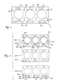
- FIG. 1 illustrates three gasket layers 100, 200 and 300 which are adapted to be assembled in stacked relation, and in a proper preselected order into an assembled gasket G, such as a head gasket for an automotive engine.
- exemplary gasket such as a head gasket G defines a plurality of service openings such as combustion openings 10, a series of smaller openings or utility apertures, such as apertures 20 for oil and coolant, and a series of bolt holes 30.
- Each gasket layer may be generally similar in its perimetric configuration.
- the assembled gasket G has been designed to function with a particular engine, in accordance with considerations which require its assembly in a predetermined sequence and stacked relationship.
- one or more layers may be stainless steel of a first thickness
- other layers such as layers 100 and 300 may be rubber coated, as with a microcoating of a type known and used in the art, on their exterior surfaces, and of stainless steel of a somewhat different thickness.
- Layer 100 may define an inwardly projecting embossment 102 around each combustion opening 104.
- Layer 200 may be devoid of embossments, whether around the combustion openings or otherwise.
- Layer 300 may define embossments 310 around coolant apertures 312. Other details adapted for providing an effective gasket G may be used as well.
- each layer 100, 200 and 300 of head gasket G defines complementary combustion openings, coolant apertures, oil apertures, bolt holes, etc., all as is known and customary in the gasketing art.
- each gasket layer also defines means for sensing the presence of each layer appropriately so that it may be recognized as having been stacked in the proper orientation and sequence.
- the means for sensing proper sequencing comprises a series of formations, such as openings located in a zone of each layer which does not affect sealing, in this case in a corner of each gasket layer 100, 200 and 300.
- gasket layer 100 defines a sensing zone 120
- layer 200 defines a sensing zone 220
- layer 300 defines a sensing zone 320.
- the sensing zones are aligned in a superposed array.
- layer 100 defines a pair of openings 121, 122 located at vertical positions B and C in zone 120
- layer 200 defines a pair of openings 221, 222 located at vertical positions A and C in zone 220
- layer 300 defines a pair of openings 321, 322 located at vertical positions A and B in zone 320.
- At least one sensing opening of a gasket layer is offset laterally and out of superposed alignment with a sensing opening in each next adjacent superposed gasket layer.
- the sequence of stacking or assembly of each gasket layer and its presence is controlled by a suitable programmed logic controller which follows the assembly of the layers via input signals from associated sensors.
- the controller enables or permits a securing or clinching operation to occur only if all of the individual gasket layers have been stacked in the proper sequence and orientation.
- the sensing formations or openings in the individual layers correspond to specific sensing devices or sensors of the sensing means and the program resident in the controller. The sensors must provide input signals to the controller in the specific programmed sequence to enable the clinching operation.
- the sequence of operation begins when the first, usually the bottom, gasket layer is positioned in an associated clinching fixture.
- This layer does not have a sensing formation or opening at the corresponding position of a selected sensor for this layer, thereby causing the sensor to register the presence of this layer in the controller as well as the fact that it is the correct layer. If the correct layer is not placed in the fixture in the correct sequence, a sensing opening may be at position A or one or more sensing openings may not be at positions B or C and the layer will not be correctly registered in the controller. The controller will not then enable the clinching operation.
- the first gasket layer is placed correctly, as many subsequent layers as required by the design of the gasket can then be stacked in their proper sequence.
- This will comprise at least two gasket layers, and usually at least three gasket layers. They will be registered in the controller as programmed, ending with the final proper layer. The controller will then enable the clinching operation which will then be accomplished.
- the completed gasket is removed from the clinching fixture. Removal will automatically clear and reset the controller memory, readying it for the stacking of the layers of the next gasket to be assembled.
- a clinching fixture 400 designed for use in securing assembling the gasket layers 100, 200 and 300 is shown in FIG. 10. It includes a stacking surface or bed 402 on which the gasket layers are adapted to be stacked in sequence.
- the bed 402 includes positioning blocks 404, 406 and may include locating pads 408 about which the gasket layer combustion openings are positioned, as well as locating pins 410, all of which contribute to the precise positioning of the stacked layers. Desirably pins 410 are off-center longitudinally of the gasket so that they will mate only with right-side up gasket layers.
- the locating holes in the gasket layers may be existing oil or coolant openings or bolt holes, or special additional holes which will not affect sealing may be provided in the gasket layers if desired.
- the bed further defines openings 418A, 418B, 418C at selected positions such as at positions A, B and C for the array or plurality of laterally offset sensors 420A, 420B and 420C of a sensing means
- Fixture 400 also includes a pair of spaced tab clinching bars 430 which are reciprocal toward and away from each other, as by pairs of pneumatically operated cylinders 432. These are adapted to force tabs, such as clinching tabs 106 at the periphery of gasket layer 100 (and which are integrally formed therewith) up and over gasket layer 300 to secure and clinch the gasket layers together, thereby to secure the layers in their preselected relationship to each other in the final gasket assembly.
- the controller will not permit the clinching to occur unless the programmed stacking of the layers has taken place in proper fashion.
- Exemplary of the typical operation of the clinching fixture and associated programmed logic controller 500 may be understood as follows. First, layer 100 is located on the fixture bed 402. It has no opening at position A (which overlies opening 418A and sensor 420A), but has openings at positions B and C. If it is a correct layer and is properly positioned, sensor 420A will recognize the absence of a sensing opening at position A and sensors 420B and 420C will recognize the presence of sensing openings at positions B and C. If it is an incorrect layer, such as a layer 200 or 300, sensor 420A will see an opening at position A. The controller 500 may be programmed to signal if an opening is absent at position A and openings are present at positions B and C.
- a typical controller 500 may be one available from Allen-Bradley of Milwaukee, Wisconsin, and identified as SLC-150.
- Typical sensors 420A, 420B and 420C may be clear fiberoptic sensors, such as those available from Keyence Corp. of Torrance, California and identified as LZ-153.
- sensor 420B will sense the absence of a superposed opening in layer 200, but sensor 420C will recognize the presence of a superposed sensing opening at position C. That will satisfy the controller 500 that layer 200 is proper and in its proper orientation relative to layer 100.
- layer 300 is positioned over layer 200 and sensor 420C then senses the absence of a sensing opening at position C therein.
- the controller 500 will have both a proper count of the layers, via an included counter, and information establishing that they have been located and stacked properly and in proper sequence.
- sensors 420B and 420C for the first layer
- sensor 420C for the second layer
- the sensors may be used simply to recognize the absence of an opening in the overlying layer to provide an enabling signal to the controller.
- the presence of the locating pins 410 may be used to assure that the layers are being positioned right side up and in their proper orientation.
- the controller is programmed to enable the clinching operation.
- the sensing formations have been illustrated as being openings positioned in a corner of each gasket layer. It will be apparent that a variety of sensors and controllers may be used.
Landscapes
- General Engineering & Computer Science (AREA)
- Engineering & Computer Science (AREA)
- Mechanical Engineering (AREA)
- Gasket Seals (AREA)
- Measurement Of Radiation (AREA)
- Analysing Materials By The Use Of Radiation (AREA)
- Sealing Battery Cases Or Jackets (AREA)
- Auxiliary Devices For And Details Of Packaging Control (AREA)
- Packaging Of Special Articles (AREA)
- Making Paper Articles (AREA)
- Cartons (AREA)
- Length-Measuring Instruments Using Mechanical Means (AREA)
- Connector Housings Or Holding Contact Members (AREA)
- Exchange Systems With Centralized Control (AREA)
- Examining Or Testing Airtightness (AREA)
- Controlling Sheets Or Webs (AREA)
- Joints Allowing Movement (AREA)
- Tyre Moulding (AREA)
Abstract
Description
Claims (3)
- A method of verifying the correct assembly of a multilayer gasket having at least three superposed layers (100, 200, 300) secured in a preselected sequence comprising the steps of:providing at least three different gasket layers, each defining at least one service opening (10) and at least one utility aperture (20) smaller than said service opening, with each said layer defining a sensing zone (120, 220, 320) which, when the layers are assembled, is aligned in a superposed array with the sensing zones of the other layers, each said sensing zone defining at least two sensing openings (121, 122; 221, 222; 321, 322) and at least one of said sensing openings (121, 222, 322) is laterally offset and out of superposed alignment with a sensing opening in each next adjacent superposed layer,providing a stacking surface (402) and an array of laterally offset sensors (420A, 420B, 420C) positioned in locations corresponding to said sensing zones,locating a first layer (100) on said stacking surface (402) with its sensing zone (120) in superposed alignment with said sensors and automatically sensing whether its sensing openings (221, 222; 321, 322) correctly correspond to a position of at least one sensor,then stacking each next layer (200, 300) over said first and next preceding layers with its sensing zone (220, 320) in superposed alignment with said sensors and automatically sensing whether its sensing openings (221, 222; 321, 322) correctly correspond to a position of at least one sensor, andautomatically providing an electrical signal that the layers (100, 200, 300) have been correctly stacked in the preselected sequence.
- The method of claim 1, wherein said stacking surface (402) is associated with a means (400) for securing said gasket layers (100, 200, 300) together in said preselected sequence, and wherein said signal enables said securing means (400) for securing said gasket layers together.
- The method of claim 2, and wherein said gasket layers (100, 200, 300) are metal and at least one (100) of said gasket layers defines clinching tabs (106), and said securing means (400) comprise means (430) for deforming said clinching tabs (106) to secure said stacked layers together.
Applications Claiming Priority (3)
| Application Number | Priority Date | Filing Date | Title |
|---|---|---|---|
| US776831 | 1985-09-17 | ||
| US07/776,831 US5210943A (en) | 1991-10-15 | 1991-10-15 | Method of verifying the correct sequence of assembly of a multilayer gasket |
| PCT/US1992/008702 WO1993008396A1 (en) | 1991-10-15 | 1992-10-13 | Multilayer gasket and method of verifying the correct sequence of assembly |
Publications (3)
| Publication Number | Publication Date |
|---|---|
| EP0608332A1 EP0608332A1 (en) | 1994-08-03 |
| EP0608332A4 EP0608332A4 (en) | 1995-11-02 |
| EP0608332B1 true EP0608332B1 (en) | 1998-06-03 |
Family
ID=25108500
Family Applications (1)
| Application Number | Title | Priority Date | Filing Date |
|---|---|---|---|
| EP92921934A Expired - Lifetime EP0608332B1 (en) | 1991-10-15 | 1992-10-13 | Multilayer gasket and method of verifying the correct sequence of assembly |
Country Status (10)
| Country | Link |
|---|---|
| US (1) | US5210943A (en) |
| EP (1) | EP0608332B1 (en) |
| JP (1) | JP2002515100A (en) |
| AT (1) | ATE166948T1 (en) |
| BR (1) | BR9206624A (en) |
| DE (1) | DE69225804T2 (en) |
| DK (1) | DK0608332T3 (en) |
| ES (1) | ES2117055T3 (en) |
| MX (1) | MX9205891A (en) |
| WO (1) | WO1993008396A1 (en) |
Families Citing this family (8)
| Publication number | Priority date | Publication date | Assignee | Title |
|---|---|---|---|---|
| WO1997000392A1 (en) * | 1995-06-19 | 1997-01-03 | Fel-Pro Incorporated | Gasket layer identifiers |
| US6409178B1 (en) * | 1999-06-09 | 2002-06-25 | Dana Corporation | Multiple layer gasket having selectively removable spacer layers and visual indicators |
| DE10031095B8 (en) * | 2000-06-30 | 2011-08-04 | ElringKlinger AG, 72581 | Method for producing a multilayer gasket and gasket |
| JP3794569B2 (en) * | 2002-06-14 | 2006-07-05 | Necトーキン株式会社 | Storage element and method for manufacturing the same |
| JP4378376B2 (en) | 2006-12-07 | 2009-12-02 | 石川ガスケット株式会社 | Metal gasket and method for manufacturing the same |
| JP2008164155A (en) * | 2007-01-05 | 2008-07-17 | Ishikawa Gasket Co Ltd | Metal gasket and method for detecting misassembly of metal gasket |
| US10421165B2 (en) * | 2017-03-21 | 2019-09-24 | Honda Motor Co., Ltd. | Apparatus and methods of installing and verifying installation of a seal member in a component |
| CN112649891B (en) * | 2020-12-22 | 2024-07-05 | 张家港孚冈汽车部件有限公司 | DPS pipeline assembly installation cushion neglected loading detection device |
Family Cites Families (5)
| Publication number | Priority date | Publication date | Assignee | Title |
|---|---|---|---|---|
| US4049856A (en) * | 1976-10-16 | 1977-09-20 | Tba Industrial Products Limited | Gaskets |
| US4648607A (en) * | 1986-03-04 | 1987-03-10 | Ishikawa Gasket Co. Ltd. | Steel laminate gasket with assembly order identification device |
| US4810454A (en) * | 1986-06-18 | 1989-03-07 | Dana Corporation | Method of manufacturing a gasket having multiple regions of different densities and thicknesses |
| US4813691A (en) * | 1988-04-21 | 1989-03-21 | Fel-Pro Incorporated | Unitized multi-layered gasket and method of making same |
| JPH0769014B2 (en) * | 1990-02-28 | 1995-07-26 | 日本ラインツ株式会社 | Laminated gasket |
-
1991
- 1991-10-15 US US07/776,831 patent/US5210943A/en not_active Expired - Lifetime
-
1992
- 1992-10-13 BR BR9206624A patent/BR9206624A/en not_active IP Right Cessation
- 1992-10-13 EP EP92921934A patent/EP0608332B1/en not_active Expired - Lifetime
- 1992-10-13 WO PCT/US1992/008702 patent/WO1993008396A1/en not_active Ceased
- 1992-10-13 AT AT92921934T patent/ATE166948T1/en not_active IP Right Cessation
- 1992-10-13 DE DE69225804T patent/DE69225804T2/en not_active Expired - Fee Related
- 1992-10-13 ES ES92921934T patent/ES2117055T3/en not_active Expired - Lifetime
- 1992-10-13 JP JP50775493A patent/JP2002515100A/en active Pending
- 1992-10-13 DK DK92921934T patent/DK0608332T3/en active
- 1992-10-14 MX MX9205891A patent/MX9205891A/en not_active IP Right Cessation
Also Published As
| Publication number | Publication date |
|---|---|
| DE69225804T2 (en) | 1999-02-04 |
| EP0608332A1 (en) | 1994-08-03 |
| ES2117055T3 (en) | 1998-08-01 |
| ATE166948T1 (en) | 1998-06-15 |
| DK0608332T3 (en) | 1998-10-12 |
| EP0608332A4 (en) | 1995-11-02 |
| DE69225804D1 (en) | 1998-07-09 |
| WO1993008396A1 (en) | 1993-04-29 |
| BR9206624A (en) | 1995-10-24 |
| MX9205891A (en) | 1993-08-01 |
| JP2002515100A (en) | 2002-05-21 |
| US5210943A (en) | 1993-05-18 |
Similar Documents
| Publication | Publication Date | Title |
|---|---|---|
| EP0338537B1 (en) | Unitized multi-layered gasket and method of making same | |
| US4648607A (en) | Steel laminate gasket with assembly order identification device | |
| US5210943A (en) | Method of verifying the correct sequence of assembly of a multilayer gasket | |
| WO1997000392A1 (en) | Gasket layer identifiers | |
| US7900936B2 (en) | Metal gasket | |
| US7914008B2 (en) | Metal gasket and mis-assembly detection method of metal gasket | |
| US5141237A (en) | Steel laminate gasket with a plate information device | |
| US5415418A (en) | Engine assembly aid | |
| JPH0989484A (en) | Plate heat exchanger | |
| JP2845420B2 (en) | Separate plate inspection gauge and separate plate inspection method | |
| Swift et al. | Strategies and case studies in assembly system selection | |
| JP2549784Y2 (en) | Switch element | |
| EP0516407B1 (en) | Method of identifying thickness of a gasket and a gasket with a plate information device | |
| US4620572A (en) | Radial reform head | |
| JPH0294692A (en) | printed wiring board | |
| JP3358288B2 (en) | Engine cylinder discriminator | |
| JP6952162B2 (en) | Circuit board and board separated from it | |
| JPS62208941A (en) | Method of laminating ceramic substrate | |
| JP4131901B2 (en) | Assembling method of continuously variable transmission belt | |
| JPS63155686A (en) | Wiring board and manufacture of the same | |
| JPH02122592A (en) | printed wiring board | |
| JP2002188980A (en) | Judgment method of element of belt for continuously variable transmission | |
| JP3084499B2 (en) | Manufacturing method of manifold gasket | |
| JPH0266992A (en) | printed wiring board | |
| JP2001062643A (en) | Spring misassembly detection method |
Legal Events
| Date | Code | Title | Description |
|---|---|---|---|
| PUAI | Public reference made under article 153(3) epc to a published international application that has entered the european phase |
Free format text: ORIGINAL CODE: 0009012 |
|
| 17P | Request for examination filed |
Effective date: 19940414 |
|
| AK | Designated contracting states |
Kind code of ref document: A1 Designated state(s): AT CH DE DK ES FR GB IT LI NL SE |
|
| A4 | Supplementary search report drawn up and despatched |
Effective date: 19950915 |
|
| AK | Designated contracting states |
Kind code of ref document: A4 Designated state(s): AT CH DE DK ES FR GB IT LI NL SE |
|
| 17Q | First examination report despatched |
Effective date: 19960826 |
|
| GRAG | Despatch of communication of intention to grant |
Free format text: ORIGINAL CODE: EPIDOS AGRA |
|
| GRAG | Despatch of communication of intention to grant |
Free format text: ORIGINAL CODE: EPIDOS AGRA |
|
| GRAG | Despatch of communication of intention to grant |
Free format text: ORIGINAL CODE: EPIDOS AGRA |
|
| GRAH | Despatch of communication of intention to grant a patent |
Free format text: ORIGINAL CODE: EPIDOS IGRA |
|
| GRAH | Despatch of communication of intention to grant a patent |
Free format text: ORIGINAL CODE: EPIDOS IGRA |
|
| GRAA | (expected) grant |
Free format text: ORIGINAL CODE: 0009210 |
|
| AK | Designated contracting states |
Kind code of ref document: B1 Designated state(s): AT CH DE DK ES FR GB IT LI NL SE |
|
| REF | Corresponds to: |
Ref document number: 166948 Country of ref document: AT Date of ref document: 19980615 Kind code of ref document: T |
|
| ITF | It: translation for a ep patent filed | ||
| REG | Reference to a national code |
Ref country code: CH Ref legal event code: NV Representative=s name: E. BLUM & CO. PATENTANWAELTE Ref country code: CH Ref legal event code: EP |
|
| REF | Corresponds to: |
Ref document number: 69225804 Country of ref document: DE Date of ref document: 19980709 |
|
| REG | Reference to a national code |
Ref country code: ES Ref legal event code: FG2A Ref document number: 2117055 Country of ref document: ES Kind code of ref document: T3 |
|
| ET | Fr: translation filed | ||
| PGFP | Annual fee paid to national office [announced via postgrant information from national office to epo] |
Ref country code: FR Payment date: 19980917 Year of fee payment: 7 |
|
| PGFP | Annual fee paid to national office [announced via postgrant information from national office to epo] |
Ref country code: SE Payment date: 19980918 Year of fee payment: 7 |
|
| PGFP | Annual fee paid to national office [announced via postgrant information from national office to epo] |
Ref country code: NL Payment date: 19980921 Year of fee payment: 7 Ref country code: DK Payment date: 19980921 Year of fee payment: 7 Ref country code: DE Payment date: 19980921 Year of fee payment: 7 Ref country code: AT Payment date: 19980921 Year of fee payment: 7 |
|
| PGFP | Annual fee paid to national office [announced via postgrant information from national office to epo] |
Ref country code: GB Payment date: 19981008 Year of fee payment: 7 |
|
| REG | Reference to a national code |
Ref country code: DK Ref legal event code: T3 |
|
| PGFP | Annual fee paid to national office [announced via postgrant information from national office to epo] |
Ref country code: ES Payment date: 19981015 Year of fee payment: 7 |
|
| PGFP | Annual fee paid to national office [announced via postgrant information from national office to epo] |
Ref country code: CH Payment date: 19981026 Year of fee payment: 7 |
|
| PLBE | No opposition filed within time limit |
Free format text: ORIGINAL CODE: 0009261 |
|
| STAA | Information on the status of an ep patent application or granted ep patent |
Free format text: STATUS: NO OPPOSITION FILED WITHIN TIME LIMIT |
|
| 26N | No opposition filed | ||
| PG25 | Lapsed in a contracting state [announced via postgrant information from national office to epo] |
Ref country code: GB Free format text: LAPSE BECAUSE OF NON-PAYMENT OF DUE FEES Effective date: 19991013 Ref country code: DK Free format text: LAPSE BECAUSE OF NON-PAYMENT OF DUE FEES Effective date: 19991013 Ref country code: AT Free format text: LAPSE BECAUSE OF NON-PAYMENT OF DUE FEES Effective date: 19991013 |
|
| PG25 | Lapsed in a contracting state [announced via postgrant information from national office to epo] |
Ref country code: ES Free format text: LAPSE BECAUSE OF NON-PAYMENT OF DUE FEES Effective date: 19991014 |
|
| PG25 | Lapsed in a contracting state [announced via postgrant information from national office to epo] |
Ref country code: SE Free format text: THE PATENT HAS BEEN ANNULLED BY A DECISION OF A NATIONAL AUTHORITY Effective date: 19991030 |
|
| PG25 | Lapsed in a contracting state [announced via postgrant information from national office to epo] |
Ref country code: LI Free format text: LAPSE BECAUSE OF NON-PAYMENT OF DUE FEES Effective date: 19991031 Ref country code: CH Free format text: LAPSE BECAUSE OF NON-PAYMENT OF DUE FEES Effective date: 19991031 |
|
| PG25 | Lapsed in a contracting state [announced via postgrant information from national office to epo] |
Ref country code: NL Free format text: LAPSE BECAUSE OF NON-PAYMENT OF DUE FEES Effective date: 20000501 |
|
| GBPC | Gb: european patent ceased through non-payment of renewal fee |
Effective date: 19991013 |
|
| REG | Reference to a national code |
Ref country code: CH Ref legal event code: PL |
|
| EUG | Se: european patent has lapsed |
Ref document number: 92921934.3 |
|
| PG25 | Lapsed in a contracting state [announced via postgrant information from national office to epo] |
Ref country code: FR Free format text: LAPSE BECAUSE OF NON-PAYMENT OF DUE FEES Effective date: 20000630 |
|
| NLV4 | Nl: lapsed or anulled due to non-payment of the annual fee |
Effective date: 20000501 |
|
| PG25 | Lapsed in a contracting state [announced via postgrant information from national office to epo] |
Ref country code: DE Free format text: LAPSE BECAUSE OF NON-PAYMENT OF DUE FEES Effective date: 20000801 |
|
| REG | Reference to a national code |
Ref country code: FR Ref legal event code: ST |
|
| REG | Reference to a national code |
Ref country code: DK Ref legal event code: EBP |
|
| REG | Reference to a national code |
Ref country code: ES Ref legal event code: FD2A Effective date: 20001113 |
|
| PG25 | Lapsed in a contracting state [announced via postgrant information from national office to epo] |
Ref country code: IT Free format text: LAPSE BECAUSE OF NON-PAYMENT OF DUE FEES;WARNING: LAPSES OF ITALIAN PATENTS WITH EFFECTIVE DATE BEFORE 2007 MAY HAVE OCCURRED AT ANY TIME BEFORE 2007. THE CORRECT EFFECTIVE DATE MAY BE DIFFERENT FROM THE ONE RECORDED. Effective date: 20051013 |