EP0608176A1 - Mist diffuser - Google Patents
Mist diffuser Download PDFInfo
- Publication number
- EP0608176A1 EP0608176A1 EP94400112A EP94400112A EP0608176A1 EP 0608176 A1 EP0608176 A1 EP 0608176A1 EP 94400112 A EP94400112 A EP 94400112A EP 94400112 A EP94400112 A EP 94400112A EP 0608176 A1 EP0608176 A1 EP 0608176A1
- Authority
- EP
- European Patent Office
- Prior art keywords
- chamber
- ring
- micro
- fractionation
- sleeve
- Prior art date
- Legal status (The legal status is an assumption and is not a legal conclusion. Google has not performed a legal analysis and makes no representation as to the accuracy of the status listed.)
- Withdrawn
Links
Images


Classifications
-
- A—HUMAN NECESSITIES
- A61—MEDICAL OR VETERINARY SCIENCE; HYGIENE
- A61L—METHODS OR APPARATUS FOR STERILISING MATERIALS OR OBJECTS IN GENERAL; DISINFECTION, STERILISATION OR DEODORISATION OF AIR; CHEMICAL ASPECTS OF BANDAGES, DRESSINGS, ABSORBENT PADS OR SURGICAL ARTICLES; MATERIALS FOR BANDAGES, DRESSINGS, ABSORBENT PADS OR SURGICAL ARTICLES
- A61L9/00—Disinfection, sterilisation or deodorisation of air
- A61L9/14—Disinfection, sterilisation or deodorisation of air using sprayed or atomised substances including air-liquid contact processes
-
- B—PERFORMING OPERATIONS; TRANSPORTING
- B05—SPRAYING OR ATOMISING IN GENERAL; APPLYING FLUENT MATERIALS TO SURFACES, IN GENERAL
- B05B—SPRAYING APPARATUS; ATOMISING APPARATUS; NOZZLES
- B05B7/00—Spraying apparatus for discharge of liquids or other fluent materials from two or more sources, e.g. of liquid and air, of powder and gas
- B05B7/0012—Apparatus for achieving spraying before discharge from the apparatus
Definitions
- the present invention relates to a micro-diffuser device, intended in particular for the purification or the regeneration of atmospheres, by dispersion in a surrounding medium of micro-particles or micro-droplets the dimensions of which are substantially homogeneous with one another and lie below a predetermined limit, in particular of the order of 1 to 2 microns at most.
- micro-diffusion devices in particular in the medical field, for phytotherapy treatments and more particularly aromatherapy, in which a very fine dispersion of oils or various essences is carried out, in particular d 'vegetable origin, to allow their respiration or their absorption by the skin or the mucous membranes of a patient.
- these devices have the drawback of producing relatively large particles, the dispersion of which is not perfect.
- the product to be dispersed consists of an aromatic oil, generally designated by the term essential oil, obtained by extraction from certain plants having particularly developed therapeutic, olfactory or antiseptic properties and the cost is generally high.
- the present invention relates to an improved micro-diffusion device which combines with an assembly in itself known, capable of providing a high flow of air under pressure resulting in a regular and determined quantity of a liquid product to be dispersed at the outlet of the device in the ambient environment, means making it possible to fractionate the entrained liquid particles to give them an extremely reduced size, substantially homogeneous throughout the dispersed volume, being situated in particular below a determined limit, these means being further arranged so as to allow acting on the fractionation threshold adopted, depending on the nature of the liquid product and the application of the device envisaged.
- the micro-diffuser considered comprising a mixer into which opens on the one hand a conduit delivering with a given flow rate a pressurized air flow, and on the other hand a supply pipe of a liquid to be sprayed, dispersed and entrained in the air flow by forming a mist admitted to the inlet orifice of a fractionation chamber provided opposite an outlet orifice for this mist in the external atmosphere,
- the fractionation chamber comprises a plurality of successive fractionation means traversed by the flow of air flowing in the chamber between the inlet and the outlet, these means providing in the chamber a series of successive baffles through which the mist entrained by the air flow undergoes as many changes of direction
- the fractionation means are constituted by adjacent hollow rings, each comprising a surface on which the flow strikes, this surface extending across the direction of flow thereof, each ring consisting of an external tubular sleeve having an axis of symmetry, open at one end and
- the patch of each ring is laterally connected to the internal surface of the sleeve on a fraction of the periphery thereof, by a full and narrow support membrane, so that the free space between the sleeve and the patch extends over at least the major part of the sleeve, surrounding the patch.
- the patch has a circular contour, extends coaxially to the sleeve and has on its face on which the impact of the air flow occurs an approximately conical profile, so that the fog driven by the air flow, after hitting the pellet, is preferably deflected and guided laterally in the direction of the free space delimited in this ring between the patch and the sleeve.
- the adjacent rings in the fractionation chamber are juxtaposed so that the passages made in the juxtaposed rings are offset from one ring to the next according to the length of the chamber, in the direction of flow of the air flow inside it.
- the fractionation chamber is constituted by an external body, delimiting an elongated internal enclosure, of generally cylindrical shape and of revolution about a longitudinal axis, the adjacent rings being housed in the chamber in succession, each ring preferably being provided with means suitable for making it possible to modify its relative orientation with respect to the longitudinal axis of the chamber in three respectively perpendicular directions, in rotation, by axial displacement and in relative inclination.
- the sleeve of each ring is externally threaded and cooperates with a homologous internal thread, provided in the internal surface of the enclosure of the fractionation chamber, to allow movement of the ring in the direction of the axis of the chamber.
- the internal surface of the body of the chamber comprises a transverse housing for mounting a helical thread screw, free in rotation with respect to the body but immobilized in translation in its housing, the latter being open partially laterally so that the screw cooperates with a toothing formed in the external surface of the sleeve of a ring at least in order to control the relative rotation of this ring around the longitudinal axis of the chamber.
- the wall of the chamber has a through circular groove, extending over a part of the contour of a ring disposed opposite and through which is engaged an operating plug, integral with this ring so that the displacement of the plug in the groove causes the rotation of the ring relative to the longitudinal axis of the chamber.
- the sleeve of at least one of the rings has a partially spherical surface and externally comprises axial trunnions engaged in holes forming support bearings provided in the internal surface of the chamber, at least one of said trunnions with a control slot, accessible from outside the body and making it possible to tilt the ring on the axis of the chamber.
- the micro-diffuser according to the invention thus makes it possible to vary, at the option of the user and according to the particular nature of each of the applications envisaged, the number and the relative arrangement of the successive rings mounted inside the fractionation chamber. depending on the length thereof, thus allowing to play on the conditions under which the impact of the air flow occurs causing the mist of liquid particles or droplets so that, by varying the number of these points impact and the flow deviations created at the right of the rings by the pellets belonging to each of them, the dispersion of the particles in the mist delivered by the outlet of the chamber can be adjusted at will, by adjusting in particular the size of these particles so that they have dimensions close to each other which are preferably below a predetermined threshold.
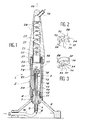
- the reference 1 generally designates a micro-diffusion device produced in accordance with a first embodiment of the invention.
- This device comprises in particular a mixer 2, which in this example is in the form of a metallic external envelope 3, of generally cylindrical shape, closed at its lower end by a shutter 4, the assembly being secured by means of pins wedging and immobilization 5 on a support 6, arranged to allow to maintain the mixer 2 in a substantially vertical position, the particular shape and structure of this support being naturally indifferent to the present invention.
- a mixer 2 which in this example is in the form of a metallic external envelope 3, of generally cylindrical shape, closed at its lower end by a shutter 4, the assembly being secured by means of pins wedging and immobilization 5 on a support 6, arranged to allow to maintain the mixer 2 in a substantially vertical position, the particular shape and structure of this support being naturally indifferent to the present invention.
- the shutter 4 has a central bore 7 and is extended by a nozzle 8, suitable for being connected to the end 9 of a pipe 10 delivering in the bore 7 and, beyond, in the mixer 2, a flow of air with a given flow rate and under a determined pressure. Joints, respectively 11 and 12, ensure the tightness of the assembly, in particular between the shutter4 and a tubular element 13, mounted coaxially inside the casing 3 by coming to fit on the projecting central part 14 l shutter 4.
- this tubular element 13 is made of a transparent material, in particular of glass of the "Pyrex" type or the like, and contains a given volume of a liquid product 15 to be sprayed by means of the device, by making with the air flow supplied by the pipe 10 a mist, formed by a homogeneous dispersion of particles or droplets of this liquid, these particles having an extremely small size and the size of which can be further adjusted at the discretion of the user. using the means which will be described below.
- a window 3a is advantageously provided in the wall of the envelope 3 in order to monitor the level of the liquid 15 in the tubular and transparent element 13 of the mixer.
- the mixer 2 comprises axially a tube 16, connecting with the bore 7 formed in the central part 14 of the shutter 4 and in which the flow flows compressed air delivered by the piping 10, this tubing ending, at its opposite end by a head 17, provided with a nozzle 18 in front of which is provided a bloom 19 by which the air escapes in the upper part 20 of the mixer.
- a fractionation chamber 22 comprising a body 23, elongated, of generally cylindrical shape and extending upward the mixer 2, this body preferably comprising a lower flange 24 screwed onto a threaded part provided at the corresponding end of the casing 3.
- a flat seal 25 is mounted between the end of the tubular element 13 and a bearing surface 26 formed in the body 23 in order to sealing the upper part of the mixer, so that the mist delivered by the nozzle 18 is completely channeled inside the fractionation chamber, in the passage 27 formed axially in the body 23, in the extension of item 13.
- the rings 28 are joined and arranged over the entire height of the passage 27, being immobilized between a bearing surface 30 at the top of this passage and a locking ring 31 mounted at the end upper part of the tubular element 13.
- FIGS 2 and 3 illustrate more precisely the particular structure of the rings 28 used in the micro-diffuser of Figure 1.
- Each of these rings is preferably in the form of a sleeve 32, of cylindrical shape and the external diameter of which corresponds substantially to the internal diameter of the passage 27, the ring also comprising, at its center, a patch 33, connected to the side wall of the sleeve 32 by a connecting membrane 34, shaped so that the patch 33 delimits between its outer contour and the internal surface of the sleeve a free space 35, of circular shape and which extends over the major part of the sleeve surrounding the patch, with the exception of the zone of connection of the latter with the sleeve by the membrane 34.
- each ring and in particular the bottom 36 of its pad 33 are preferably shaped so as to have a substantially conical profile, the top 37 of which coincides approximately with the axis 29 of the passage 27 when the ring is mounted in the latter.
- the operation of the device illustrated on the Fi gure 1 is easily deduced from the above description.
- the fractionation chamber 22, equipped with all of the superimposed rings 28, mounted as shown in passage 27, is fixed to the end of the mixer 2, by screwing onto the latter.
- This is then started by sending to the nozzle 18 a stream of pressurized air supplied by an appropriate source (not shown) and admitted by the piping 10 into the mixer, simultaneously causing the suction of an appropriate quantity of liquid from the volume 15 through the conduit 21, the nozzle 18 continuously supplying in the upper part 20 of the tubular casing 13 a mist formed by the dispersion of the particles or droplets of this liquid in the flow of 'air.
- this mist enters the fractionation chamber 22 and goes towards the first ring 28 against which the flow charged with liquid comes to strike, in particular in the region of its central pellet 33 in the direction of the apex 37 of the cone formed in the opposite face of this patch, which deflects it laterally towards the space 35 by which it can pass through the ring and come to meet the next ring 28, and so on to the opposite end of the chamber.
- the fog entrained by the air flow undergoes, thus on crossing the fractionation chamber a path according to successive baffles with, in each of the rings, a change of direction and an impact on the corresponding pellet, allowing, as experience demonstrates, to fractionate into particles or droplets of increasingly fine size the entrained liquid fraction, until the latter is evacuated from the chamber by an outlet nozzle 38 provided at its upper part.
- the air flow at the inlet is for example between 150 and 200 l / h, preferably of the order of 170 l / h, with a number of rings between 6 and 10 and preferably of the order of 8, it is possible to obtain a mist at the outlet of the apparatus in which the sprayed liquid particles have a substantially constant particle size at room temperature, with an extremely homogeneous size of these particles. the order, or even less than 2 microns, each ring ensuring in a way a momentary trapping of the largest particles and a fractionation of these, the effect of the various rings accumulating from the entry to the exit from the room.
- the average particle size of the particles in the delivered mist can in particular be checked using a conventional device of the type known as the Anderersen impactor or even by means of a laser particle sizer.
- the sprayed liquid can be of any suitable nature but is preferably constituted by a so-called "essential” oil, based on plant essences, having in particular a strong disinfection and / or purification power of the ambient atmosphere.
- essential oil based on plant essences, having in particular a strong disinfection and / or purification power of the ambient atmosphere.
- eucalyptus essence or any other suitable aromatic oil essence can thus be used.
- the power of fractionation of the micro-diffuser according to the invention can be further improved if the various rings 28 which form the baffles of the chamber 22 at the outlet of the mixer 2 can have from one to the other a variable orientation or even be arranged in so that their distance or their relative inclination can be modified and adjusted from one ring to the next in particular.
- Figures 4 to 7 schematically illustrate various embodiments of mechanisms thus making it possible to act on the rings individually to vary their respective presentation on the path of the fog entrained by the air flow at the outlet of the mixer.
- the internal wall of the passage 27 in which the rings 28 are arranged has a thread 43, making it possible in the same way to orient the relative position of each ring but also to move it ci in the direction of the axis 29, following a number of appropriate turns of this ring with respect to the thread.
- a ring 28 whose outer surface 44 has a cylindrical profile, this ring being provided with two pins, respectively 45 and 46, penetrating holes or bores such as 47 and 48 formed in the internal wall of the body 23 to form support bearings for the ring, one of the pins being provided with a groove 49 accessible from the outside of the chamber 22 and making it possible to orient the ring, in particular by tilting it opposite axis 29 in passage 27.
- the body 23 comprises, in line with the ring 28, a transverse groove 50, the ring being provided with a blind housing 51 in which the end of a plug 52, capable of moving, can engage. using a control button 53 inside the groove 50, orienting the position of the ring 28 around the axis 29.
- Figure 8 illustrates another alternative embodiment of the micro-diffuser device according to the invention, in which there is nevertheless a mixer 2 and, at the outlet thereof, a fractionation chamber 22.
- this Figure has also used identical reference numbers to designate members similar to those used in the first embodiment according to FIG. 1.
- the compressed air conveyed by a pipe 54 connecting to the inlet pipe 10 of the mixer 2 ensures the dispersion of a liquid product withdrawn by means of a tube 55 under the level 56 of a reserve of it contained in a large container 57.
- the mixer additionally comprises means making it possible to recover the liquid particles which, due to their impact on the rings 28 in the fractionation chamber 22, separate from the flow air and fall back to the mixer, the liquid collected in the bottom of the latter being taken up by a tube 58 and returned by an overflow line 59 to the tank 57.
- the liquid which flows partially on the walls of the chamber and which is therefore not entrained by the mist in the collecting space 60 formed beyond the stack of rings and into which the outlet spout 38 opens is recovered by a second overflow pipe 61 to be similarly returned to the tank 57, in order to avoid any loss or waste.
- sensors 62 in the plug 63 which closes the upper part of the chamber 22, these sensors making it possible to permanently control the pressure of the mist delivered, and also to control the particle size of the latter, for example by means of a fractional or continuous sample, transmitted to a measuring device (not shown).
- Figure 9 illustrates another variant of a transportable device, comprising a casing 64 supported by rollers 65 which allow it to be moved on the ground at will.
- This casing contains a compressor 66, driven by an electric motor 67 energized by means of a connection wire 68.
- the lower part of the casing 64 forms a tank 69 for storing an appropriate volume of the liquid 70 to spray.
- the structure of the device is similar to that of those described above.
- the fractionation chamber 22 can advantageously be designed so that it is itself formed of several successive parts such as 71 and 72 (FIG. 10), each of these parts containing a stack of rings 28 as already described, this solution making it possible to further increase the power of fractionation and dispersion of the mist before it is delivered to the outside environment by the outlet nozzle 38.
- a micro-diffuser of very simple design is thus produced which makes it possible to satisfy a very large number of applications, in particular in the field of the purification of an ambient atmosphere, the disinfection of premises, air conditioning or deodorization.
- other variants are of course conceivable, in particular in the medical field for certain aromatherapy treatments or even for all applications where it is a question of having a very finely divided liquid mist and in which the particles dispersed liquids have a uniform size, less than a given limit.
- the microdiffusion device comprising in the fractionation chamber 22 the stack of rings 28, can be used to optimally spray the fluid delivered by a combustion burner, for example of the type '' a hydrocarbon, for industrial or domestic use.
- the piping 10 which brings the air flow to the mixer 2, comprises a nozzle 73, which delivers a mixture of this fluid with this air according to a jet under pressure, the latter then passing through the fractionation chamber 22 while crossing the successive rings 28 until they end up in the closure plug 63 provided at the opposite end of this chamber, this plug being provided in its center with a calibrated orifice 74 through which the jet of sprayed fluid 75 is projected at the exterior in an extremely divided form, with a homogeneous particle size of the particles which it comprises.
Landscapes
- Health & Medical Sciences (AREA)
- Epidemiology (AREA)
- Life Sciences & Earth Sciences (AREA)
- Animal Behavior & Ethology (AREA)
- General Health & Medical Sciences (AREA)
- Public Health (AREA)
- Veterinary Medicine (AREA)
- Nozzles (AREA)
Abstract
Description
La présente invention est relative à un appareil micro-diffuseur, destiné notamment à la purification ou à la régénération d'ambiances, par dispersion dans un milieu environnant de micro-particules ou micro-gouttelettes dont les dimensions sont sensiblement homogènes entre elles et se situent en dessous d'une limite prédéterminée, en particulier de l'ordre de 1 à 2 microns au plus.The present invention relates to a micro-diffuser device, intended in particular for the purification or the regeneration of atmospheres, by dispersion in a surrounding medium of micro-particles or micro-droplets the dimensions of which are substantially homogeneous with one another and lie below a predetermined limit, in particular of the order of 1 to 2 microns at most.
On connaît déjà des réalisations d'appareils de micro-diffusion, en particulier dans le domaine médical, pour des traitements de phytothérapie et plus spécialement d'aromathérapie, dans lesquels on procède à une dispersion très fine d'huiles ou essences diverses, notamment d'origine végétale, pour permettre leur respiration ou leur absorption par la peau ou les muqueuses d'un patient. Toutefois, ces appareils ont l'inconvénient de produire des particules relativement grandes et dont la dispersion n'est pas parfaite.There are already known embodiments of micro-diffusion devices, in particular in the medical field, for phytotherapy treatments and more particularly aromatherapy, in which a very fine dispersion of oils or various essences is carried out, in particular d 'vegetable origin, to allow their respiration or their absorption by the skin or the mucous membranes of a patient. However, these devices have the drawback of producing relatively large particles, the dispersion of which is not perfect.
On sait par ailleurs que la régénération de certaines ambiances particulièrement polluées, notamment pour réaliser leur désodorisation, fait appel à la pulvérisation dans l'atmosphère correspondante de certains produits présentant une activité appropriée, permettant également et selon le cas de désinfecter ou de revitaliser l'air appauvri. Dans ces applications également, il est bien connu que la régénération de l'air est d'autant plus efficace que la susbstance pulvérisée est mieux dispersée et se présente sous la forme de particules très fines, aptes à former un brouillard ou un aérosol susceptible de se répartir uniformément et efficacement dans l'ensemble du volume d'air à traiter.We also know that the regeneration of certain particularly polluted atmospheres, in particular to achieve their deodorization, calls for the spraying into the corresponding atmosphere of certain products having an appropriate activity, also making it possible and depending on the case to disinfect or revitalize the depleted air. In these applications also, it is well known that the regeneration of the air is all the more effective as the sprayed substance is better dispersed and is in the form of very fine particles, capable of forming a mist or an aerosol capable of distribute evenly and efficiently throughout the volume of air to be treated.
Les mêmes impératifs sont à satisfaire, pour des raisons sensiblement analogues, dans d'autres domaines où l'on fait aussi appel à une dispersion fine de gouttelettes liquides de très faible taille, notamment pour la pulvérisation en agriculture d'insecticides, herbicides ou fongicides, ou encore dans les injecteurs de moteurs à combustion, ou même dans les lances ou diffuseurs de produits contre l'incendie.The same imperatives must be satisfied, for substantially similar reasons, in other fields where use is also made of a fine dispersion of very small liquid droplets, in particular for spraying insecticides, herbicides or fungicides in agriculture. , or even in injectors of combustion engines, or even in lances or diffusers of fire-fighting products.
En outre, quelle que soit l'application envisagée, le contrôle de la taille des particules dispersées, notamment pour que celle-ci se situe en-deçà d'une seui 1 prédéterminé, permet de n'utiliser que les quantités strictement indispensables du produit diffusé pour satisfaire aux conditions de mise en oeuvre de l'application prévue, le produit utilisé pouvant dans certains cas être très coûteux, d'où l'intérêt immédiat d'éviter tout gaspillage ou perte inutile.In addition, whatever the application envisaged, controlling the size of the dispersed particles, in particular so that it is below a
C'est le cas en particulier lorsque le produit à disperser est constitué par une huile aromatique, généralement désignée sous le terme d'huile essentielle, obtenue par extraction à partir de certains végétaux ayant des propriétés thérapeutiques, olfactives ou antiseptiques particulièrement développées et dont le coût est généralement élevé.This is the case in particular when the product to be dispersed consists of an aromatic oil, generally designated by the term essential oil, obtained by extraction from certain plants having particularly developed therapeutic, olfactory or antiseptic properties and the cost is generally high.
La présente invention concerne un appareil de micro-diffusion perfectionné qui allie à un ensemble en lui-même connu, apte à fournir un débit élevé d'air sous pression entraînant une quantité régulière et déterminée d'un produit liquide à disperser à la sortie de l'appareil dans l'environnement ambiant, des moyens permettant de fractionner les particules liquides entraînées pour leur donner une taille extrêmement réduite, sensiblement homogène dans l'ensemble du volume dispersé, en se situant en particulier en dessous d'une limite déterminée, ces moyens étant en outre agencés de manière à permettre d'agir sur le seuil de fractionnement adopté, en fonction de la nature du produit liquide et de l'application de l'appareil envisagée.The present invention relates to an improved micro-diffusion device which combines with an assembly in itself known, capable of providing a high flow of air under pressure resulting in a regular and determined quantity of a liquid product to be dispersed at the outlet of the device in the ambient environment, means making it possible to fractionate the entrained liquid particles to give them an extremely reduced size, substantially homogeneous throughout the dispersed volume, being situated in particular below a determined limit, these means being further arranged so as to allow acting on the fractionation threshold adopted, depending on the nature of the liquid product and the application of the device envisaged.
A cet effet et selon l'invention, le micro-diffuseur considéré, comportant un mélangeur dans lequel débouche d'une part un conduit délivrant avec un débit donné un flux d'air sous pression, et d'autre part une tubulure d'amenée d'un liquide à pulvériser, dispersé et entraîné dans le flux d'air en formant un brouillard admis à l'orifice d'entrée d'une chambre de fractionnement munie à l'opposé d'un orifice de sortie de ce brouillard dans l'atmosphère extérieure, dans lequel la chambre de fractionnement comprend une pluralité de moyens de fractionnement successifs traversés par le flux d'airs'écoulant dans la chambre entre l'orifice d'entrée et l'orifice de sortie, ces moyens ménageant dans la chambre une série de chicanes successives à travers lesquelles le brouillard entraîné par le flux d'air subit autant de changements de direction, se caractérise en ce que les moyens de fractionnement sont constitués par des bagues creuses adjacentes, comportant chacune une surface sur laquelle vient frapper le flux, cette surface s'étendant en travers du sens d'écoulement de celui-ci, chaque bague étant constituée d'un manchon tubulaire externe présentant un axe de symétrie, ouvert à une extrémité et comportant à l'extrémité opposée une pastille disposée transversalement par rapport au sens d'écoulement du flux, la pastille ayant une surface plus réduite que la section droite du manchon de manière à délimiter avec celui-ci un espace ouvert pour le passage du brouillard traversant la bague, consécutivement à l'impact du flux sur la pastille.To this end and according to the invention, the micro-diffuser considered, comprising a mixer into which opens on the one hand a conduit delivering with a given flow rate a pressurized air flow, and on the other hand a supply pipe of a liquid to be sprayed, dispersed and entrained in the air flow by forming a mist admitted to the inlet orifice of a fractionation chamber provided opposite an outlet orifice for this mist in the external atmosphere, in which the fractionation chamber comprises a plurality of successive fractionation means traversed by the flow of air flowing in the chamber between the inlet and the outlet, these means providing in the chamber a series of successive baffles through which the mist entrained by the air flow undergoes as many changes of direction, is characterized in that the fractionation means are constituted by adjacent hollow rings, each comprising a surface on which the flow strikes, this surface extending across the direction of flow thereof, each ring consisting of an external tubular sleeve having an axis of symmetry, open at one end and comprising at the the opposite end of a pellet disposed transversely to the direction of flow, the pellet having a smaller surface than the cross section of the sleeve so as to delimit therewith an open space for the passage of the mist passing through the ring, following the impact of the flux on the pellet.
Dans un mode de réalisation préféré, la pastille de chaque bague est raccordée latéralement à la surface interne du manchon sur une fraction du pourtour de celui-ci, par une membrane de support pleine et étroite, de telle sorte que l'espace libre entre le manchon et la pastille s'étende sur la majeure partie au moins du manchon, en entourant la pastille.In a preferred embodiment, the patch of each ring is laterally connected to the internal surface of the sleeve on a fraction of the periphery thereof, by a full and narrow support membrane, so that the free space between the sleeve and the patch extends over at least the major part of the sleeve, surrounding the patch.
Selon une caractéristique particulière de l'invention, la pastille comporte un contour circulaire, s'étend coaxialement au manchon et présente dans sa face sur lequel se produit l'impact du flux d'air un profil approximativement conique, de telle sorte que le brouillard entraîné par le flux d'air, après avoirfrap- pé la pastille, soit préférentiellement dévié et guidé latéralement en direction de l'espace libre délimité dans cette bague entre la pastille et le manchon.According to a particular characteristic of the invention, the patch has a circular contour, extends coaxially to the sleeve and has on its face on which the impact of the air flow occurs an approximately conical profile, so that the fog driven by the air flow, after hitting the pellet, is preferably deflected and guided laterally in the direction of the free space delimited in this ring between the patch and the sleeve.
Selon encore une autre caractéristique du micro-diffuseur considéré, les bagues adjacentes dans la chambre de fractionnement sont juxtaposées de telle sorte que les passages ménagés dans les bagues juxtaposées soient décalés d'une bague à la suivante selon la longueur de la chambre, dans le sens d'écoulement du flux d'air à l'intérieur de celle-ci.According to yet another characteristic of the micro-diffuser considered, the adjacent rings in the fractionation chamber are juxtaposed so that the passages made in the juxtaposed rings are offset from one ring to the next according to the length of the chamber, in the direction of flow of the air flow inside it.
De préférence, la chambre de fractionnement est constituée par un corps externe, délimitant une enceinte interne allongée, de forme générale cylindrique et de révolution autour d'un axe longitudinal, les bagues adjacentes étant logées dans la chambre en succession, chaque bague étant de préférence munie de moyens propres à permettre de modifier son orientation relative par rapport à l'axe longitudinal de la chambre selon trois directions respectivement perpendiculaires, en rotation, par déplacement axial et en inclinaison relative.Preferably, the fractionation chamber is constituted by an external body, delimiting an elongated internal enclosure, of generally cylindrical shape and of revolution about a longitudinal axis, the adjacent rings being housed in the chamber in succession, each ring preferably being provided with means suitable for making it possible to modify its relative orientation with respect to the longitudinal axis of the chamber in three respectively perpendicular directions, in rotation, by axial displacement and in relative inclination.
Selon une première variante d'exécution, le manchon de chaque bague est fileté extérieurement et coopère avec un filetage interne homologue, prévu dans la surface interne de l'enceinte de la chambre de fractionnement, pour permettre un déplacement de la bague selon la direction de l'axe de la chambre.According to a first alternative embodiment, the sleeve of each ring is externally threaded and cooperates with a homologous internal thread, provided in the internal surface of the enclosure of the fractionation chamber, to allow movement of the ring in the direction of the axis of the chamber.
Selon une autre variante, la surface interne du corps de la chambre comprend un logement transversal pour le montage d'une vis à filet hélicoïdal, libre en rotation vis-à-vis du corps mais immobilisée en translation dans son logement, celui-ci étant ouvert en partie latéralement de manière à ce que la vis coopère avec une denture ménagée dans la surface externe du manchon d'une bague au moins afin de commander la rotation relative de cette bague autour de l'axe longitudinal de la chambre.According to another variant, the internal surface of the body of the chamber comprises a transverse housing for mounting a helical thread screw, free in rotation with respect to the body but immobilized in translation in its housing, the latter being open partially laterally so that the screw cooperates with a toothing formed in the external surface of the sleeve of a ring at least in order to control the relative rotation of this ring around the longitudinal axis of the chamber.
Dans encore une autre variante de réalisation, la paroi de la chambre comporte une rainure circulaire traversante, s'étendant sur une partie du contour d'une bague disposée en regard et à travers laquelle est engagée une fiche de manoeuvre, solidaire de cette bague de telle sorte que le déplacement de la fiche dans la rainure provoque la rotation de la bague par rapport à l'axe longitudinal de la chambre.In yet another alternative embodiment, the wall of the chamber has a through circular groove, extending over a part of the contour of a ring disposed opposite and through which is engaged an operating plug, integral with this ring so that the displacement of the plug in the groove causes the rotation of the ring relative to the longitudinal axis of the chamber.
Dans un autre mode de réalisation, le manchon d'une au moins des bagues présente une surface partiellement sphérique et comporte extérieurement des tourillons axiaux engagés dans des trous formant paliers de support prévus dans la surface interne de la chambre, l'un au moins desdits tourillons comportant une fente de commande, accessible de l'extérieur du corps et permettant d'incliner la bague sur l'axe de la chambre.In another embodiment, the sleeve of at least one of the rings has a partially spherical surface and externally comprises axial trunnions engaged in holes forming support bearings provided in the internal surface of the chamber, at least one of said trunnions with a control slot, accessible from outside the body and making it possible to tilt the ring on the axis of the chamber.
Le micro-diffuseur selon l'invention permet ainsi de faire varier, au gré de l'utilisateur et selon la nature particulière de chacune des applications envisagées, le nombre et la disposition relative des bagues successives montées à l'intérieur de la chambre de fractionnement selon la longueur de celle-ci, en permettant ainsi de jouer sur les conditions dans lesquelles se produit l'i mpact du flux d'air entraînant le brouillard de particules ou gouttelettes liquides de telle sorte que, en faisant varier le nombre de ces points d'impact et les déviations du flux créées au droit des bagues par les pastilles appartenant à chacune de celles-ci, la dispersion des particules dans le brouillard délivré par l'orifice de sortie de la chambre puisse être ajustée à volonté, en réglant notamment la taille de ces particules de manière qu'elles présentent des dimensions voisines entre elles qui se situent de préférence en-deçà d'un seuil prédéterminé.The micro-diffuser according to the invention thus makes it possible to vary, at the option of the user and according to the particular nature of each of the applications envisaged, the number and the relative arrangement of the successive rings mounted inside the fractionation chamber. depending on the length thereof, thus allowing to play on the conditions under which the impact of the air flow occurs causing the mist of liquid particles or droplets so that, by varying the number of these points impact and the flow deviations created at the right of the rings by the pellets belonging to each of them, the dispersion of the particles in the mist delivered by the outlet of the chamber can be adjusted at will, by adjusting in particular the size of these particles so that they have dimensions close to each other which are preferably below a predetermined threshold.
D'autres caractéristiques d'un micro-diffuseur réalisé conformément à l'invention apparaîtront encore à travers la description qui suit de plusieurs exemples de réalisation, donnés à titre indicatif et non limitatif, en référence aux dessins annexés sur lesquels :
- - La Figure 1 est une vue en coupe longitudinale d'un micro-diffuseur réalisé conformément à un premier mode de réalisation de l'invention.
- - Les Figures 2 et 3 sont des vues à plus grande échelle en perspective et en coupe partielle d'une bague mise en oeuvre dans la chambre de fractionnement du micro-diffuseur selon la Figure 1, cette bague étant respectivement représentée vue de dessus et de dessous afin d'illustrer de façon plus détaillée ses caractéristiques de forme et notamment le profil de la pastille centrale qu'elle comporte.
- - Les Figures 4a et 4b sont des vues respectivement en coupe transversale et longitudinale, à légèrement plus grande échelle, d'une bague montée dans la chambre de fractionnement du micro-diffuseur et associée à des moyens permettant de faire varier l'orientation relative de cette bague par rapport à l'axe de la chambre.
- - Les Figures 5a et 5b, 6a et 6b, 7a et 7b sont des vues analogues aux Figures 3a et 3b illustrant d'autres moyens propres à modifier l'orientation de chacune des bagues montées dans la chambre de fractionnement afin de faire varier respectivement sa position axiale, son orientation en azimuth et sa position angulaire par rapport à l'axe de la chambre de fractionnement.
- - Les Figures 8 et 9 sont des vues plus schématiques en coupe axiale de deux autres variantes de réalisation du micro-diffuseur selon l'invention.
- - La Figure 10 est une vue de détail d'une adaptation possible du mode de réalisation selon la Figure 7.
- - La Figure 11 est une vue en coupe longitudinale d'une autre variante.
- - Figure 1 is a longitudinal sectional view of a micro-diffuser produced in accordance with a first embodiment of the invention.
- - Figures 2 and 3 are views on a larger scale in perspective and in partial section of a ring used in the fractionation chamber of the micro-diffuser according to Figure 1, this ring being shown respectively from above and from below in order to illustrate in more detail its shape characteristics and in particular the profile of the central patch which it comprises.
- - Figures 4a and 4b are views respectively in transverse and longitudinal section, on a slightly larger scale, of a ring mounted in the fractionation chamber of the micro-diffuser and associated with means making it possible to vary the relative orientation of this ring relative to the axis of the chamber.
- - Figures 5a and 5b, 6a and 6b, 7a and 7b are views similar to Figures 3a and 3b illustrating other means suitable for modifying the orientation of each of the rings mounted in the fractionation chamber in order to vary its axial position, its azimuth orientation and its angular position relative to the axis of the fractionation chamber.
- - Figures 8 and 9 are more schematic views in axial section of two other alternative embodiments of the micro-diffuser according to the invention.
- - Figure 10 is a detail view of a possible adaptation of the embodiment according to Figure 7.
- - Figure 11 is a longitudinal sectional view of another variant.
Sur la Figure 1, la référence 1 désigne de façon générale un appareil de micro-diffusion réalisé conformément à un premier mode de réalisation de l'invention.In Figure 1, the
Cet appareil comporte notamment un mélangeur 2, se présentant dans cet exemple sous la forme d'une enveloppe externe métallique 3, de forme générale cylindrique, fermée à son extrémité inférieure par un obturateur 4, l'ensemble étant assujetti par l'intermédiaire de pions de calage et d'immobilisation 5 sur un support 6, aménagé de manière à permettre de maintenir le mélangeur 2 en position sensiblement verticale, la forme et la structure particulières de ce support étant naturellement indifférentes à l'égard de la présente invention.This device comprises in particular a
L'obturateur 4 comporte un alésage central 7 et se prolonge par un embout 8, propre à être raccordé à l'extrémité 9 d'une tuyauterie 10 délivrant dans l'alésage 7 et, au-delà, dans le mélangeur 2, un flux d'air avec un débit donné et sous une pression déterminée. Des joints, respectivement 11 et 12, assurent l'étanchéité du montage, notamment entre l'obturateur4 et un élément tubulaire 13, monté coaxialement à l'intérieur de l'enveloppe 3 en venant s'emboîter sur la partie centrale en saillie 14 l'obturateur 4. Avantageusement, cet élément tubulaire 13 est réalisé en un matériau transparent, notamment en verre du type "Pyrex" ou autre, et contient un volume donné d'un produit liquide 15 à pulvériser au moyen de l'appareil, en réalisant avec le flux d'air amené par la tuyauterie 10 un brouillard, formé par une dispersion homogène de particules ou gouttelettes de ce liquide, ces particules présentant une taille extrêmement réduite et dont la dimension peut être en outre ajustée au gré de l'utilisateur à l'aide des moyens qui seront décrits ci-après. Une fenêtre 3a est avantageusement prévue dans la paroi de l'enveloppe 3 afin de surveiller le niveau du liquide 15 dans l'élément tubulaire et transparent 13 du mélangeur.The
De façon en elle-même classique dans la technique des appareils de pulvérisation, le mélangeur 2 comporte axialement une tubulure 16, se raccordant avec l'alésage 7 ménagé dans la partie centrale 14 de l'obturateur 4 et dans laquelle s'écoule le flux d'air comprimé délivré par la tuyauterie 10, cette tubulure se terminant, à son extrémité opposée par une tête 17, munie d'une buse 18 devant laquelle est ménagé un épanouissement 19 par lequel l'airs'échappe dans la partie supérieure 20 du mélangeur. Au niveau de la buse 18, débouche par ailleurs un conduit21 dirigé vers le bas et dont l'extrémité inférieure ouverte plonge dans le volume de liquide 15 contenu dans le mélangeur à l'intérieur de l'élément tubulaire 13, la dépression créée au droit de la buse 18 par l'écoulement du flux d'air sous pression et l'épanouissement 19 de la tête 17, agissant à la manière d'un Venturi, provoquant une aspiration continue du liquide à travers le conduit 21, suivie d'une dispersion de ce liquide dans la partie supérieure 20 à l'intérieur de l'enveloppe 3.In itself conventional in the technique of spraying apparatus, the
Sur cette enveloppe, est alors mise en place, conformément à l'invention, une chambre de fractionnement 22, comportant un corps 23, allongé, de forme générale cylindrique et prolongeant vers le haut le mélangeur 2, ce corps comprenant de préférence une collerette inférieure 24 se vissant sur une partie filetée prévue à l'extrémité correspondante de l'enveloppe 3. Un joint plat 25 est monté entre l'extrémité de l'élément tubulaire 13 et une portée d'appui 26 ménagée dans le corps 23 afin d'assurer l'étanchéité de la partie supérieure du mélangeur, de telle sorte que le brouillard délivré par la buse 18 soit totalement canalisé à l'intérieur de la chambre de fractionnement, dans le passage 27 ménagé axialement dans le corps 23, dans le prolongement de l'élément 13.On this envelope, is then set up, in accordance with the invention, a
Selon l'invention, on dispose alors à l'intérieur du passage 27 une pluralité de bagues cylindriques 28, adjacentes et qui, selon le cas, peuvent être directement juxtaposées les unes aux autres, comme illustré sur la Figure 1, ou bien sontséparées d'une bague à la suivante par un espace approprié, permettant, comme décrit ci-après, de faire varier à la demande la position relative de ces bagues vis-à-vis de l'axe central de la chambre de fractionnement 22, cet axe étant schématisé sur le dessin sous la référence 29.According to the invention, there is then placed inside the passage 27 a plurality of
Dans le mode de réalisation représenté, les bagues 28 sont accolées et disposées sur toute la hauteur du passage 27, en étant immobilisées entre une portée d'appui 30 à la partie supérieure de ce passage et une bague de blocage 31 montée à l'extrémité supérieure de l'élément tubulaire 13.In the embodiment shown, the
Les Figures 2 et 3 illustrent de façon plus précise la structure particulière des bagues 28 mises en oeuvre dans le micro-diffuseur de la Figure 1. Chacune de ces bagues se présente de préférence sous la forme d'un manchon 32, de forme cylindrique et dont le diamètre externe correspond sensiblement au diamètre interne du passage 27, la bague comportant par ailleurs, en son centre, une pastille 33, raccordée à la paroi latérale du manchon 32 par une membrane 34 de liaison, conformée de telle sorte que la pastille 33 délimite entre son contour extérieur et la surface interne du manchon un espace libre 35, de forme circulaire et qui s'étend sur la majeure partie du manchon en entourant la pastille, à l'exception de la zone de liaison de celle-ci avec le manchon par la membrane 34.Figures 2 and 3 illustrate more precisely the particular structure of the
Bien entendu, la largeur de l'espace 35 ainsi ménagé dans chaque bague 28 dépend du diamètre de la pastille centrale 33 et des conditions d'utilisation de la bague, telles que précisées ci-après. En outre, chaque bague et notamment le fond 36 de sa pastille 33 sont de préférence conformés de manière à présenter un profil sensiblement conique, dont le sommet 37 coïncide approximativement avec l'axe 29 du passage 27 lorsque la bague est montée dans ce dernier.Of course, the width of the
Le fonctionnement de l'appareil illustré sur la Figure 1 se déduit aisément de la description qui précède. La chambre de fractionnement 22, équipée de l'ensemble des bagues 28 superposées, montées comme représenté dans le passage 27, est fixée sur l'extrémité du mélangeur 2, par vissage sur ce dernier. Celui-ci est alors mis en route par l'envoi vers la buse 18 d'un flux d'air sous pression délivré par une source appropriée (non représentée) et admis par la tuyauterie 10 dans le mélangeur, provoquant simultanément l'aspiration d'une quantité appropriée de liquide à partir du volume 15 à travers le conduit 21, la buse 18 fournissant en continu dans la partie supérieure 20 de l'enveloppe tubulaire 13 un brouillard formé parla dispersion des particules ou gouttelettes de ce liquide dans le débit d'air.The operation of the device illustrated on the
Sous l'effet de la pression, ce brouillard pénètre dans la chambre de fractionnement 22 et se dirige vers la première bague 28 contre laquelle le flux chargé de liquide vient frapper, notamment dans la région de sa pastille centrale 33 en direction du sommet 37 du cône ménagé dans la face en regard de cette pastille, qui le dévie latéralement vers l'espace 35 par lequel il peut franchir la bague et venir rencontrer la bague 28 suivante, et ainsi de suite jusqu'à l'extrémité opposée de la chambre.Under the effect of the pressure, this mist enters the
Le brouillard entraîné par le flux d'air subit, ainsi à la traversée de la chambre de fractionnement un trajet selon des chicanes successives avec, dans chacune des bagues, un changement de direction et un impactsurla pastille correspondante, permettant, comme l'expérience le démontre, de fractionner en particules ou gouttelettes de taille de plus en plus fine la fraction liquide entraînée, jusqu'à ce que cette dernière soit évacuée de la chambre par un bec de sortie 38 prévu à sa partie supérieure.The fog entrained by the air flow undergoes, thus on crossing the fractionation chamber a path according to successive baffles with, in each of the rings, a change of direction and an impact on the corresponding pellet, allowing, as experience demonstrates, to fractionate into particles or droplets of increasingly fine size the entrained liquid fraction, until the latter is evacuated from the chamber by an
On constate notamment qu'avec un tel appareil, dans lequel le débit d'air à l'entrée est par exemple compris entre 150 et 200 I/h, de préférence de l'ordre de 170 I/h, avec un nombre de bagues entre 6 et 10 et de préférence de l'ordre de 8, on peut obtenir un brouillard à la sortie de l'appareil dans lequel les particules liquides pulvérisées présentent une granulométrie sensiblement constante à température ambiante, avec une dimension extrêmement homogène de ces particules de l'ordre, voire même inférieure à 2 microns, chaque bague assurant en quelque sorte un piégeage momentané des particules les plus grosses et un fractionnement de celles-ci, l'effet des diverses bagues se cumulant depuis l'entrée jusqu'à la sortie de la chambre. La granulométrie moyenne des particules dans le brouillard délivré peut être notamment contrôlée à l'aide d'un appareil classique du genre de celui connu sous le terme d'impacteurd'An- dersen ou encore au moyen d'un granulomètre à laser.We note in particular that with such a device, in which the air flow at the inlet is for example between 150 and 200 l / h, preferably of the order of 170 l / h, with a number of rings between 6 and 10 and preferably of the order of 8, it is possible to obtain a mist at the outlet of the apparatus in which the sprayed liquid particles have a substantially constant particle size at room temperature, with an extremely homogeneous size of these particles. the order, or even less than 2 microns, each ring ensuring in a way a momentary trapping of the largest particles and a fractionation of these, the effect of the various rings accumulating from the entry to the exit from the room. The average particle size of the particles in the delivered mist can in particular be checked using a conventional device of the type known as the Anderersen impactor or even by means of a laser particle sizer.
Le liquide pulvérisé peut être de toute nature appropriée mais est de préférence constitué par une huile dite "essentielle", à base d'essences végétales, présentant notamment un fort pouvoir de désinfection et/ou de purification de l'atmosphère ambiante. A titre indicatif, on peut ainsi utiliser de l'essence d'eucalyptus ou encore toute autre essence d'huile aromatique appropriée.The sprayed liquid can be of any suitable nature but is preferably constituted by a so-called "essential" oil, based on plant essences, having in particular a strong disinfection and / or purification power of the ambient atmosphere. As an indication, eucalyptus essence or any other suitable aromatic oil essence can thus be used.
On a toutefois constaté que, avec certains autres produits pour des applications différentes et non pas seulement pour la production d'un brouillard désodorisant, par exemple pour la purification ou la désinfection de certaines atmosphères ou la réalisation d'injecteurs de carburant, le pouvoir de fractionnement du micro-diffuseur selon l'invention peut encore être amélioré si les diverses bagues 28 qui forment les chicanes de la chambre 22 à la sortie du mélangeur 2 peuvent présenter de l'une à l'autre une orientation variable ou encore être agencées de telle sorte que leur distance ou leur inclinaison relative puissent être modifiées et ajustées d'une bague à la suivante notamment.However, it has been found that, with certain other products for different applications and not only for the production of a deodorizing mist, for example for the purification or disinfection of certain atmospheres or the production of fuel injectors, the power of fractionation of the micro-diffuser according to the invention can be further improved if the
Les Figures 4 à 7 illustrent schématiquement divers modes de réalisation de mécanismes permettant ainsi d'agir sur les bagues individuellement pour faire varier leur présentation respective sur le trajet du brouillard entraîné par le flux d'air à la sortie du mélangeur.Figures 4 to 7 schematically illustrate various embodiments of mechanisms thus making it possible to act on the rings individually to vary their respective presentation on the path of the fog entrained by the air flow at the outlet of the mixer.
A la Figure 4, on a ainsi envisagé de monter dans la paroi du corps 23 de la chambre 22 une vis transversale 39, comportant un filet hélicoidal 40 en prise avec une denture 41 prévue dans la surface externe du manchon 32 de la bague 28 correspondante, la rotation de cette vis au moyen d'un outil approprié coopérant avec une rainure 42 ménagée dans la tête de celle-ci, immobilisée en translation mais libre en rotation, permettant ainsi de faire tourner la bague sur elle-même autour de l'axe 29 de la chambre et parsui- i-te de modifier la position relative de l'espace libre 35 entourant la pastille 33 et par lequel s'échappe le brouillard lors de son entraînement, en passant de cette bague à la suivante.In Figure 4, it has thus been envisaged to mount in the wall of the
Sur la Figure 5, illustrant un autre mode de réalisation, la paroi interne du passage 27 dans lequel sont disposées les bagues 28 comporte un filetage 43, permettant de la même manière d'orienter la position relative de chaque bague mais également de déplacer celle-ci selon la direction de l'axe 29, consécutivement à un nombre de tours appropriés de cette bague vis-à-vis du filetage.In FIG. 5, illustrating another embodiment, the internal wall of the
Sur la variante selon la Figure 6, on a représenté une bague 28 dont la surface externe 44 présente un profil cylindrique, cette bague étant munie de deux tourillons, respectivement 45 et 46, pénétrant dans des trous ou alésages tels que 47 et 48 ménagés dans la paroi interne du corps 23 pour former des paliers de support de la bague, l'un des tourillons étant muni d'une rainure 49 accessible de l'extérieur de la chambre 22 et permettant d'orienter la bague, notamment en l'inclinant vis-à-vis de l'axe 29 dans le passage 27.On the variant according to Figure 6, there is shown a
Sur la Figure 7 enfin, le corps 23 comporte au droit de la bague 28 une rainure transversale 50, la bague étant munie d'un logement borgne 51 dans lequel peut s'engager l'extrémité d'une fiche 52, susceptible de se déplacer à l'aide d'une bouton de commande 53 à l'intérieur de la rainure 50, en orientant la position de la bague 28 autour de l'axe 29.Finally, in FIG. 7, the
Bien entendu, il va de soi que l'Homme de l'art pourra aisément envisager d'autres modes de réalisation pour les bagues montées dans le passage cylindrique de la chambre de fractionnement, afin d'assurer selon les besoins de l'application prévue une modification ou un changement commandé d'orientation de chacune des bagues, voire seulement d'une ou de plusieurs d'entre elles, afin d'ajuster leur orientation relative et l'effet de dispersion et de réduction en taille des particules liquides contenues dans le brouillar délivré par le mélangeur situé en amont de cette chambre.Of course, it goes without saying that a person skilled in the art can easily envisage other embodiments for the rings mounted in the cylindrical passage of the fractionation chamber, in order to ensure according to the needs of the intended application. a modification or a controlled change of orientation of each of the rings, or even only of one or more of them, in order to adjust their relative orientation and the effect of dispersion and reduction in size of the liquid particles contained in the brouillar delivered by the mixer located upstream of this chamber.
La Figure 8 illustre une autre variante de réalisation de l'appareil micro-diffuseur selon l'invention, dans lequel on retrouve néanmoins un mélangeur 2 et, à la sortie de celui-ci, une chambre de fractionnement 22. Sur cette Figure, on a en outre repris des chiffres de référence identiques pour désigner des organes semblables à ceux utilisés dans le premier mode de réalisation selon la Figure 1.Figure 8 illustrates another alternative embodiment of the micro-diffuser device according to the invention, in which there is nevertheless a
Dans cette variante, l'air comprimé acheminé par une conduite 54 se raccordant à la tuyauterie d'entrée 10 du mélangeur 2, assure la dispersion d'un produit liquide prélevé au moyen d'une tubulure 55 sous le niveau 56 d'une réserve de celui-ci contenue dans un bac 57 de grande dimension.In this variant, the compressed air conveyed by a
Le mélangeur, dont la structure est pour le reste très voisine de celle déjà décrite, comporte en plus des moyens permettant de récupérer les particules liquides qui, du fait de leur impact sur les bagues 28 dans la chambre de fractionnement 22, se séparent du flux d'air et retombent vers le mélangeur, le liquide recueilli dans le fond de ce dernier étant repris par une tubulure 58 et renvoyé par une conduite de trop-plein 59 vers le bac 57. De même, à la partie supérieure de la chambre 22, le liquide qui ruisselle en partie sur les parois de la chambre et qui n'est donc pas entraîné par le brouillard dans l'espace collecteur 60 ménagé au-delà de l'empilement des bagues et dans lequel débouche le bec de sortie 38, est récupéré par une seconde conduite de trop-plein 61 pour être de façon analogue renvoyé dans le bac 57, afin d'éviter toute perte ou gaspillage. Dans cet exemple, on peut avantageusement prévoir de monter des capteurs 62 dans le bouchon 63 qui ferme la partie supérieure de la chambre 22, ces capteurs permettant de contrôler en permanence la pression du brouillard délivré, et également de contrôler la granulométrie de ce dernier, par exemple au moyen d'un prélèvement fractionné ou continu, transmis à un appareil de mesure (non représenté).The mixer, the structure of which is very similar to that already described, additionally comprises means making it possible to recover the liquid particles which, due to their impact on the
La Figure 9 illustre une autre variante d'un appareil transportable, comportant un carter 64 supporté par des roulettes 65 qui permettent de le déplacer sur le sol à volonté. Ce carter contient un compresseur 66, entraîné par un moteur électrique 67 mis sous tension au moyen d'un fil de connexion 68. En outre, la partie inférieure du carter 64 forme bac 69 pour le stockage d'un volume approprié du liquide 70 à pulvériser. Pour le reste, la structure de l'appareil est semblable à celle de ceux décrits dans ce qui précède. Toutefois, la chambre de fractionnement 22 peut être avantageusement conçue de telle sorte qu'elle soit elle-même formée de plusieurs parties successives telles que 71 et 72 (Figure 10), chacune de ces parties contenant un empilage de bagues 28 comme déjà décrit, cette solution permettant d'accroître encore le pouvoir de fractionnement et de dispersion du brouillard avant qu'il ne soit délivré vers l'environnement extérieur par le bec de sortie 38.Figure 9 illustrates another variant of a transportable device, comprising a
On réalise ainsi un micro-diffuseur de conception très simple qui permet de satisfaire à de très nombreuses applications, en particulier dans le domaine de la purification d'une atmosphère ambiante, de la désinfection de locaux, de la climatisation ou de la désodorisation. Comme déjà précisé, d'autres variantes sont bien entendu envisageables, en particulier dans le domaine médical pour certains traitements d'aromathérapie ou encore pour toutes applications où il s'agit de disposer d'un brouillard liquide très finement divisé et dans lequel les particules liquides dispersées ont une taille homogène, inférieure à une limite donnée.A micro-diffuser of very simple design is thus produced which makes it possible to satisfy a very large number of applications, in particular in the field of the purification of an ambient atmosphere, the disinfection of premises, air conditioning or deodorization. As already specified, other variants are of course conceivable, in particular in the medical field for certain aromatherapy treatments or even for all applications where it is a question of having a very finely divided liquid mist and in which the particles dispersed liquids have a uniform size, less than a given limit.
Il donc de soi que l'invention ne se limite pas aux exemples plus spécialement décrits et représentés en référence aux dessins annexés ; elle en embrasse au contraire toutes les variantes couvertes par les revendications ci-après. Ainsi et comme illustré sur la Figure 11, le dispositif de microdiffusion, comportant dans la chambre de fractionnement 22 l'empilement des bagues 28, peut être utilisé pour pulvériser de manière optimale le fluide délivré par un brûleur de combustion, par exemple du genre d'un hydrocarbure, à usage industriel ou domestique.It is therefore obvious that the invention is not limited to the examples more especially described and represented with reference to the appended drawings; on the contrary, it embraces all the variants covered by the claims below. Thus and as illustrated in FIG. 11, the microdiffusion device, comprising in the
Dans cette variante, la tuyauterie 10 qui amène le flux d'air au mélangeur 2, comporte une buse 73, qui délivre un mélange de ce fluide avec cet air selon un jet sous pression, ce dernier traversant ensuite la chambre de fractionnement 22 en franchissant les bagues 28 successives jusqu'à aboutir dans le bouchon de fermeture 63 prévu à l'extrémité opposée de cette chambre, ce bouchon étant muni en son centre d'un orifice calibré 74 à travers lequel le jet de fluide pulvérisé 75 est projeté à l'extérieur sous une forme extrêmement divisée, avec une granulométrie homogène des particules qu'il comporte.In this variant, the piping 10 which brings the air flow to the
Une telle solution permet d'obtenir une flamme efficace, brûlant dans des conditions optimales et n'exigeant qu'une consommation réduite.Such a solution makes it possible to obtain an effective flame, burning under optimal conditions and requiring only reduced consumption.
Claims (12)
Applications Claiming Priority (2)
| Application Number | Priority Date | Filing Date | Title |
|---|---|---|---|
| FR9300482A FR2700482B1 (en) | 1993-01-19 | 1993-01-19 | MICRO-DIFFUSER FOR FOG OF LIQUID PARTICLES. |
| FR9300482 | 1993-01-19 |
Publications (1)
| Publication Number | Publication Date |
|---|---|
| EP0608176A1 true EP0608176A1 (en) | 1994-07-27 |
Family
ID=9443170
Family Applications (1)
| Application Number | Title | Priority Date | Filing Date |
|---|---|---|---|
| EP94400112A Withdrawn EP0608176A1 (en) | 1993-01-19 | 1994-01-18 | Mist diffuser |
Country Status (3)
| Country | Link |
|---|---|
| EP (1) | EP0608176A1 (en) |
| FR (1) | FR2700482B1 (en) |
| WO (1) | WO1994016823A1 (en) |
Cited By (15)
| Publication number | Priority date | Publication date | Assignee | Title |
|---|---|---|---|---|
| EP0694314A1 (en) * | 1993-07-02 | 1996-01-31 | PAUL RITZAU PARI-WERK GmbH | Inhalation nebuliser with detachable reservoir for the product to nebulise |
| WO1997041910A1 (en) * | 1996-05-02 | 1997-11-13 | Euro-Celtique S.A. | Device for separating a particle fraction in an inspired air flow |
| WO1998009731A1 (en) * | 1996-09-06 | 1998-03-12 | Msp Corporation | Method and apparatus for controlled particle deposition on surfaces |
| FR2767492A1 (en) * | 1997-08-25 | 1999-02-26 | Prolitec | Nebulizer producing a fine mist of liquid droplets to mix with an immiscible liquid |
| EP0909566A2 (en) * | 1997-06-13 | 1999-04-21 | Engineered Medical Systems, Inc. | Integral nebulizer stand and carrier gas conduit |
| WO1999047273A2 (en) * | 1998-03-18 | 1999-09-23 | Lytesyde L.L.C. | Medication processing system and method |
| FR2776947A1 (en) | 1998-04-03 | 1999-10-08 | Parfum Indigo | IMPROVED NEBULIZER AND NEBULIZATION CONTROL SYSTEM |
| WO2002024262A2 (en) * | 2000-09-20 | 2002-03-28 | Bon F Del | Inhalator and pertaining atomizer |
| EP1757370A3 (en) * | 2005-08-24 | 2007-06-13 | Brother Kogyo Kabushiki Kaisha | Film forming apparatus and jetting nozzle |
| EP1882481A1 (en) * | 2006-07-27 | 2008-01-30 | Air & D- Sarl | Deodorization process and device therefor |
| WO2009080892A1 (en) * | 2007-12-20 | 2009-07-02 | Beneq Oy | Device for forming aerosol, and method and apparatus for coating glass |
| EP2340854A1 (en) * | 2009-12-15 | 2011-07-06 | Air & D- Sarl | Device and method for removing contaminants |
| EP2875871A4 (en) * | 2012-07-20 | 2016-04-20 | Europ De Servicios E Higiene Euro Servhi S A | Air freshener atomiser and method |
| WO2018219693A1 (en) * | 2017-05-30 | 2018-12-06 | Bielomatik Leuze Gmbh + Co. Kg | Aerosol device and method for providing an aerosol |
| US10918757B2 (en) | 2014-02-12 | 2021-02-16 | Presensia | Device and method for diffusing dry fog |
Families Citing this family (2)
| Publication number | Priority date | Publication date | Assignee | Title |
|---|---|---|---|---|
| FR2947191B1 (en) | 2009-06-30 | 2012-08-24 | Klipair | DIPHASIC SPRAY NOZZLE AND NEBULIZING APPARATUS HAVING THE SAME |
| CN115976460B (en) * | 2022-12-28 | 2024-08-13 | 湖州恒辉科技有限公司 | No muffle formula atmosphere stove |
Citations (3)
| Publication number | Priority date | Publication date | Assignee | Title |
|---|---|---|---|---|
| FR954901A (en) * | 1950-01-06 | |||
| GB726916A (en) * | 1951-03-30 | 1955-03-23 | Gauchard Fernand | Filters for aerosol generators |
| US4049200A (en) * | 1976-04-05 | 1977-09-20 | Sobol Jacob M | Nebulizer |
-
1993
- 1993-01-19 FR FR9300482A patent/FR2700482B1/en not_active Expired - Fee Related
-
1994
- 1994-01-18 WO PCT/FR1994/000059 patent/WO1994016823A1/en unknown
- 1994-01-18 EP EP94400112A patent/EP0608176A1/en not_active Withdrawn
Patent Citations (3)
| Publication number | Priority date | Publication date | Assignee | Title |
|---|---|---|---|---|
| FR954901A (en) * | 1950-01-06 | |||
| GB726916A (en) * | 1951-03-30 | 1955-03-23 | Gauchard Fernand | Filters for aerosol generators |
| US4049200A (en) * | 1976-04-05 | 1977-09-20 | Sobol Jacob M | Nebulizer |
Non-Patent Citations (1)
| Title |
|---|
| Bearn Mecanique Aviation Facture, 07-12-86. |
Cited By (32)
| Publication number | Priority date | Publication date | Assignee | Title |
|---|---|---|---|---|
| EP0694314A1 (en) * | 1993-07-02 | 1996-01-31 | PAUL RITZAU PARI-WERK GmbH | Inhalation nebuliser with detachable reservoir for the product to nebulise |
| WO1997041910A1 (en) * | 1996-05-02 | 1997-11-13 | Euro-Celtique S.A. | Device for separating a particle fraction in an inspired air flow |
| WO1998009731A1 (en) * | 1996-09-06 | 1998-03-12 | Msp Corporation | Method and apparatus for controlled particle deposition on surfaces |
| US5916640A (en) * | 1996-09-06 | 1999-06-29 | Msp Corporation | Method and apparatus for controlled particle deposition on surfaces |
| EP0909566A2 (en) * | 1997-06-13 | 1999-04-21 | Engineered Medical Systems, Inc. | Integral nebulizer stand and carrier gas conduit |
| EP0909566A3 (en) * | 1997-06-13 | 1999-11-03 | Engineered Medical Systems, Inc. | Integral nebulizer stand and carrier gas conduit |
| US6405944B1 (en) | 1997-08-25 | 2002-06-18 | Sarl Prolitec | Spraying attachment and appliance |
| FR2767492A1 (en) * | 1997-08-25 | 1999-02-26 | Prolitec | Nebulizer producing a fine mist of liquid droplets to mix with an immiscible liquid |
| WO1999010104A1 (en) * | 1997-08-25 | 1999-03-04 | Societe Prolitec S.A.R.L. | Spraying attachment and appliance |
| AU760330B2 (en) * | 1997-08-25 | 2003-05-15 | Societe Prolitec Sa | Spraying attachment and appliance |
| WO1999047273A2 (en) * | 1998-03-18 | 1999-09-23 | Lytesyde L.L.C. | Medication processing system and method |
| WO1999047273A3 (en) * | 1998-03-18 | 1999-11-25 | Lytesyde L L C | Medication processing system and method |
| FR2776947A1 (en) | 1998-04-03 | 1999-10-08 | Parfum Indigo | IMPROVED NEBULIZER AND NEBULIZATION CONTROL SYSTEM |
| US6328233B1 (en) | 1998-04-03 | 2001-12-11 | Parfum Indigo | Sprayer and system for controlled spraying |
| WO1999051358A1 (en) | 1998-04-03 | 1999-10-14 | Parfum Indigo | Improved sprayer and system for controlled spraying |
| WO2002024262A2 (en) * | 2000-09-20 | 2002-03-28 | Bon F Del | Inhalator and pertaining atomizer |
| WO2002024262A3 (en) * | 2000-09-20 | 2002-11-07 | Bon F Del | Inhalator and pertaining atomizer |
| CN1299779C (en) * | 2000-09-20 | 2007-02-14 | 弗朗哥·德伯恩 | Inhalator and pertaining atomizer |
| EP1757370A3 (en) * | 2005-08-24 | 2007-06-13 | Brother Kogyo Kabushiki Kaisha | Film forming apparatus and jetting nozzle |
| US7866578B2 (en) | 2005-08-24 | 2011-01-11 | Brother Kogyo Kabushiki Kaisha | Film forming apparatus and jetting nozzle |
| EP1882481A1 (en) * | 2006-07-27 | 2008-01-30 | Air & D- Sarl | Deodorization process and device therefor |
| US20100258652A1 (en) * | 2007-12-20 | 2010-10-14 | Beneq Oy | Device for forming aerosol, and method and apparatus for coating glass |
| US20100330377A1 (en) * | 2007-12-20 | 2010-12-30 | Beneq Oy | Device for forming aerosol, and method and apparatus for coating glass |
| WO2009080892A1 (en) * | 2007-12-20 | 2009-07-02 | Beneq Oy | Device for forming aerosol, and method and apparatus for coating glass |
| EA018506B1 (en) * | 2007-12-20 | 2013-08-30 | Бенек Ой | Device for forming aerosol, and method and apparatus for coating glass |
| EA021546B1 (en) * | 2007-12-20 | 2015-07-30 | Бенек Ой | Method and apparatus for forming coating on glass surface |
| EP2241540A3 (en) * | 2007-12-20 | 2016-03-30 | Beneq Oy | Device for forming aerosol, and method and apparatus for coating glass |
| EP2340854A1 (en) * | 2009-12-15 | 2011-07-06 | Air & D- Sarl | Device and method for removing contaminants |
| EP2875871A4 (en) * | 2012-07-20 | 2016-04-20 | Europ De Servicios E Higiene Euro Servhi S A | Air freshener atomiser and method |
| US10918757B2 (en) | 2014-02-12 | 2021-02-16 | Presensia | Device and method for diffusing dry fog |
| WO2018219693A1 (en) * | 2017-05-30 | 2018-12-06 | Bielomatik Leuze Gmbh + Co. Kg | Aerosol device and method for providing an aerosol |
| US11724270B2 (en) | 2017-05-30 | 2023-08-15 | Dropsa Bm Germany Gmbh | Aerosol device and method for providing an aerosol |
Also Published As
| Publication number | Publication date |
|---|---|
| FR2700482A1 (en) | 1994-07-22 |
| WO1994016823A1 (en) | 1994-08-04 |
| FR2700482B1 (en) | 1995-06-23 |
Similar Documents
| Publication | Publication Date | Title |
|---|---|---|
| EP0608176A1 (en) | Mist diffuser | |
| EP1007220B1 (en) | Spraying attachment and appliance | |
| EP3126057B1 (en) | Device and method for diffusing a dry mist | |
| CH615606A5 (en) | ||
| EP0437155A1 (en) | Method for spraying a liquid solution by ultrasound, and droplet diffuser for this method | |
| EP1899021A1 (en) | Liquid mist fire extinguisher and use thereof | |
| WO2019048761A1 (en) | Device for generating droplets from a liquid comprising improved means for diffusion of the mist, and method for implementing same | |
| EP2416895A2 (en) | Cleaning device for spray gun | |
| EP1804926A1 (en) | Low-pressure flow-controlled powder spreader | |
| FR2891474A1 (en) | Mist sprayer e.g. for cooling or disinfecting air in enclosed building has centrifugal fan to generate gas flow carrying liquid droplets | |
| EP1893340A2 (en) | Autonomous spraying device having a rotating disc | |
| EP3681645B1 (en) | Device for generating droplets from a liquid comprising improved ventilation means, and method for implementing same | |
| EP1539363B1 (en) | Liquid spraying device and agricultural machinery equipped with at least one device | |
| WO1996023530A1 (en) | Fluid fumigating device | |
| BE1028008B1 (en) | ATOMIZER FOR SPRAYING A LIQUID | |
| FR2781678A1 (en) | Sprayer for liquid product such as disinfectant has diffuser mounted axially in air flow produced by turbine in recessed end of compression chamber | |
| FR2694500A1 (en) | Atomiser for treatment of respiratory problems - includes reservoir containing treatment fluid with fluid being atomised by compressed air, and also having baffles to vary size of atomised droplets. | |
| FR2873587A1 (en) | APPARATUS FOR DIFFUSION OF ACTIVE COMPOUNDS IN THE ATMOSPHERE | |
| FR2844210A1 (en) | Liquid atomizer for agricultural sprayer has frusto-conical downwardly flared surface to disperse liquid into gas flow | |
| EP0655282A1 (en) | Apparatus for nebulizing odoriferous liquids | |
| FR2507105A1 (en) | Hand held crop sprayer - has support arm with rotatable atomiser at end and axial fan in cowl shaped to control flow | |
| WO1994026230A1 (en) | Individual treatment cubicle | |
| FR2844211A1 (en) | Agricultural spray atomizer, for dispersing fungicides and weed killer, has diffusion surface defined on conical rotor in gas flow and with drop forming ridge | |
| BE382619A (en) | ||
| BE485306A (en) |
Legal Events
| Date | Code | Title | Description |
|---|---|---|---|
| PUAI | Public reference made under article 153(3) epc to a published international application that has entered the european phase |
Free format text: ORIGINAL CODE: 0009012 |
|
| AK | Designated contracting states |
Kind code of ref document: A1 Designated state(s): BE DE ES FR GB IT NL |
|
| 17P | Request for examination filed |
Effective date: 19950227 |
|
| 17Q | First examination report despatched |
Effective date: 19960311 |
|
| RAP1 | Party data changed (applicant data changed or rights of an application transferred) |
Owner name: BMB SARL |
|
| STAA | Information on the status of an ep patent application or granted ep patent |
Free format text: STATUS: THE APPLICATION IS DEEMED TO BE WITHDRAWN |
|
| 18D | Application deemed to be withdrawn |
Effective date: 19961022 |