EP0607938B1 - Method and apparatus comprising two magnetic sensors and one laser meter for measuring the thickness of a film - Google Patents
Method and apparatus comprising two magnetic sensors and one laser meter for measuring the thickness of a film Download PDFInfo
- Publication number
- EP0607938B1 EP0607938B1 EP94100712A EP94100712A EP0607938B1 EP 0607938 B1 EP0607938 B1 EP 0607938B1 EP 94100712 A EP94100712 A EP 94100712A EP 94100712 A EP94100712 A EP 94100712A EP 0607938 B1 EP0607938 B1 EP 0607938B1
- Authority
- EP
- European Patent Office
- Prior art keywords
- magnetic sensors
- film
- distance
- cylinder
- laser
- Prior art date
- Legal status (The legal status is an assumption and is not a legal conclusion. Google has not performed a legal analysis and makes no representation as to the accuracy of the status listed.)
- Expired - Lifetime
Links
- 238000000034 method Methods 0.000 title claims description 12
- 239000002184 metal Substances 0.000 claims abstract description 20
- 238000005259 measurement Methods 0.000 claims description 25
- 230000003287 optical effect Effects 0.000 claims description 3
- 239000010408 film Substances 0.000 abstract description 22
- 239000010409 thin film Substances 0.000 abstract description 2
- 238000010586 diagram Methods 0.000 description 4
- 239000011159 matrix material Substances 0.000 description 3
- 230000005855 radiation Effects 0.000 description 3
- 239000000463 material Substances 0.000 description 2
- 230000007547 defect Effects 0.000 description 1
- 238000001514 detection method Methods 0.000 description 1
- 238000013507 mapping Methods 0.000 description 1
- 238000012986 modification Methods 0.000 description 1
- 230000004048 modification Effects 0.000 description 1
Images


Classifications
-
- G—PHYSICS
- G01—MEASURING; TESTING
- G01B—MEASURING LENGTH, THICKNESS OR SIMILAR LINEAR DIMENSIONS; MEASURING ANGLES; MEASURING AREAS; MEASURING IRREGULARITIES OF SURFACES OR CONTOURS
- G01B21/00—Measuring arrangements or details thereof, where the measuring technique is not covered by the other groups of this subclass, unspecified or not relevant
- G01B21/02—Measuring arrangements or details thereof, where the measuring technique is not covered by the other groups of this subclass, unspecified or not relevant for measuring length, width, or thickness
- G01B21/08—Measuring arrangements or details thereof, where the measuring technique is not covered by the other groups of this subclass, unspecified or not relevant for measuring length, width, or thickness for measuring thickness
Definitions
- This invention proposes an apparatus and the relevant method for measuring the thickness of a thin film while the film moves forward.
- the apparatus includes a metal cylinder, on which the film to be measured is caused to pass, and a scanning head that moves alternately along a slide parallel to the cylinder axis and comprises a pair of magnetic sensors and a laser sensor placed between the two magnetic sensors.
- the magnetic sensors sense the distance of the cylinder surface in correspondence with the points where the sensors are fitted; the distance of the cylinder in correspondence with the point where the laser measurements is performed is then obtained by interpolation.
- the laser senses the distance of the surface of the film, the thickness of which is obtained as the difference between the two measurements.
- a reading is to be performed in a zone where the cylinder surface exhibits, relative to the axis, a profile that is known a priori .
- a reading is then performed by means of the first sensor with the scanning head held standstill, sensing the surface in correspondence with a plan perpendicular to the axis; the reading is repeated by means of the remaining sensors with the head held standstill, in correspondence with the same zone.
- the comparison between the readings performed allows the difference between magnetic the sensor curves and the laser one to be detected, in order to accurately calibrate the machine.
- Apparatuses for measuring the thickness of a film while the film is moving are known.
- apparatuses comprising a scanning head that moves along a slide in a direction perpendicular to the film forward movement including a radiation emitter, said radiations being detected by a sensor, such as a ionization chamber, moving with the emitter and arranged the opposite side relative to the film, are known.
- the thickness of the material can be calculated as a function of the amount of radiation detected.
- Another system provides the utilization of a magnetic sensor coupled to a laser sensor.
- the film is passed on a metal cylinder while the head with the two sensors moves along an axis parallel to the cylinder one.
- the magnetic sensor senses the distance of the cylinder metal surface while the laser measures the distance of the film surface.
- the reading is performed while the cylinder is rotating, it is obvious that the sensors, that move parallel to the cylinder axis and lie at a distance of some centimeters from one another, perform detection (at the same height along the axis) at different times. Owing to the cylinder rotation, the reading is then effected in different positions of the cylinder surface, the angular distance of which positions is a function of the film forward speed.
- British patent n. GB 2.217.835 to Kineron describes a machine which offers a part solution of the problem and provides for utilizing a magnetic sensor on which a slot where the laser sensor is fitted is provided in correspondence with the central zone.
- a gauge device like the one described the above mentioned document GB 2,217,835 is also described in US 4,977,853.
- DE 3,929,469 A1 describes a gauge device which differs from those described in GB 2,217,835 and US 4,977,853 in that the magnetic sensor, which measures the distance of a metal reference surface, and the optical sensor, which measures the distance of the free side of a web in contact with said metal reference surface, operate on parallel but different measuring axis. It is obvious for the skilled reader that the reliability of such arrangement is limited by the unavoidable profile unevennesses of said metal reference surface.
- This invention proposes now an apparatus according to claim 1 and the relevant method for measuring the thickness of a film according to claim 5, which allow a further improvement in the results obtained by said known machines to be achieved.
- the apparatus includes a scanning head fitted with a pair of magnetic sensors between which a laser meter is fitted.
- the distance of the cylindrical surface in correspondence with the zone where the measurement by the laser is effected is obtained by interpolation between the measurements performed by the magnetic sensors.
- the laser measures then the distance of the film surface and the thickness is obtained with adequate accuracy as the difference between said values.
- the machine provides, moreover, a self-calibration function.
- a zone shaped so that the cylinder surface exhibits a known profile is provided in correspondence with a cylinder end, said zone having preferably its surface subdivided into more cylindrical profile sectors with different diameters; in such zone three measurements are performed, one by each sensor, each measurement being performed in the same point as the previous ones and with the scanning head held standstill.
- Each sensor thereby senses exactly the same surface known a priori , and it is therefore possible to determine, from the comparison between the measurements performed, the difference between the magnetic sensors' and the laser sensor's response curves.
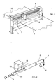
- the machine includes a frame 1 on which a metal cylinder 2 with smooth ground surface is mounted, on which frame the sheet of material to be measured, indicated by 3, is slided.
- the cylinder is preferably driven by an electric motor 4 or the like or it can be dragged by sheet 3 while moving forward.
- connection between motor and cylinder is by means of a ratchet 5 that allows the cylinder to rotate even while the motor is stopped.
- the cylinder angular position is detected, instant after instant, by an encoder 6 connected to electronic machine control devices which are not illustrated since they are of a known type.
- the scanning head 9 includes a pair of magnetic sensors 11 and 12 and a laser sensor 13 placed between the two magnetic ones.
- Sensors 11 and 12 have the capability of measuring the distance of the cylinder surface from the scanning head while the laser sensor senses the distance of sheet 3 surface.
- the cylinder radius in the point where the magnetic sensor is at the time of measurement, owing to a working imperfection, is a few microns lower than the cylinder radius in the zone where the laser sensor performs its reading.
- the method according to the invention provides for the cylinder surface to be sensed by both sensors 11 and 12 and for the calculation, by interpolation, of the cylinder surface distance in correspondence with the zone where the laser performs its reading.
- the film thickness in that point is determined by simply subtracting the two measured values.
- the cylinder surface is not round but it presents more sectors with variable radius, e.g. with the profile illustrated in figure 2.
- a second encoder checks the angular position of this part of the cylinder.
- the scanning head is brought in correspondence with such zone 14 of the cylinder and a first reading is performed, holding the head standstill, by sensing the cylinder surface in correspondence with a plane perpendicular to the axis by means of one of the magnetic sensors.
- the head is then moved, thereby bringing the laser sensor in correspondence with the same point and the reading is performed again, the same reading being thereafter repeated upon bringing to the same point the second sensor.
- Three readings are then available, all relevant to the same surface known a priori , that allow, by comparison, to calibrate the machine by adjusting the response curves of the magnetic sensors as a function of the readings values given by the laser.
- Figure 4 shows a block diagram relative to such calibration function.
- the calibration zone shall be preferably obtained in correspondence with one of the cylinder ends and such cylinder part assigned to calibration may be set to rotate independently from the remaining part. Such an arrangement allows the calibration at an optimum revolving speed, both with the main roller stopped and during the film sliding, to be performed.
- the film thickness in a given point is given by the difference between the distance as measured by the laser and the distance obtained based on the suitably averaged measurements of the two magnetic sensors.
- Th(x, ⁇ ) L(x, ⁇ ) - M(x, ⁇ )
- a matrix constiting of a series of cells each corresponding to a cylinder surface zone defined in any case by abscissa and angular position is formed and, at every passage of the heads, the values read in the zones corresponding to the different cells are stored.
- the reading heads perform a series of scannings by moving in a direction parallel to the cylinder axis and, for each reading, the program checks whether the values corresponding to the zones comprised between the reading points between the two magnetic sensors are stored in the table.
- the magnetic sensor readings are stored and inserted into the matrix where they replace the previous ones, in order to keep the table updated and thereby compensate for possible variations or reading errors due e.g. to temperature variations etc.
- FIG. 3 shows the block diagram of the above method.
Landscapes
- Physics & Mathematics (AREA)
- General Physics & Mathematics (AREA)
- Length Measuring Devices By Optical Means (AREA)
- Measurement Of Length, Angles, Or The Like Using Electric Or Magnetic Means (AREA)
- Length Measuring Devices With Unspecified Measuring Means (AREA)
Abstract
Description
- This invention proposes an apparatus and the relevant method for measuring the thickness of a thin film while the film moves forward.
- The apparatus includes a metal cylinder, on which the film to be measured is caused to pass, and a scanning head that moves alternately along a slide parallel to the cylinder axis and comprises a pair of magnetic sensors and a laser sensor placed between the two magnetic sensors.
- The magnetic sensors sense the distance of the cylinder surface in correspondence with the points where the sensors are fitted; the distance of the cylinder in correspondence with the point where the laser measurements is performed is then obtained by interpolation.
- The laser senses the distance of the surface of the film, the thickness of which is obtained as the difference between the two measurements.
- In order to calibrate the apparatus, compensating for the difference between the magnetic sensors and the laser sensor reading curves, a reading is to be performed in a zone where the cylinder surface exhibits, relative to the axis, a profile that is known a priori.
- A reading is then performed by means of the first sensor with the scanning head held standstill, sensing the surface in correspondence with a plan perpendicular to the axis; the reading is repeated by means of the remaining sensors with the head held standstill, in correspondence with the same zone.
- The comparison between the readings performed allows the difference between magnetic the sensor curves and the laser one to be detected, in order to accurately calibrate the machine.
- Apparatuses for measuring the thickness of a film while the film is moving are known.
- For instance apparatuses comprising a scanning head that moves along a slide in a direction perpendicular to the film forward movement including a radiation emitter, said radiations being detected by a sensor, such as a ionization chamber, moving with the emitter and arranged the opposite side relative to the film, are known.
- The thickness of the material can be calculated as a function of the amount of radiation detected.
- Another system provides the utilization of a magnetic sensor coupled to a laser sensor.
- In such a case the film is passed on a metal cylinder while the head with the two sensors moves along an axis parallel to the cylinder one.
- The magnetic sensor senses the distance of the cylinder metal surface while the laser measures the distance of the film surface.
- The difference between such two measurements indicates the thickness.
- In many cases it is however necessary to keep the measurement tolerances within very low values, in the range of one micron, and with the known apparatuses there are considerable difficulties due, e.g., to the cylinder surface unevennesses.
- Since the reading is performed while the cylinder is rotating, it is obvious that the sensors, that move parallel to the cylinder axis and lie at a distance of some centimeters from one another, perform detection (at the same height along the axis) at different times. Owing to the cylinder rotation, the reading is then effected in different positions of the cylinder surface, the angular distance of which positions is a function of the film forward speed.
- On the other hand, it is not possible to slow down the film speed withouth delaying work, nor is it possible to increase beyond given limits the head scanning speed.
- As a consequence this problem has not yet been entirely solved.
- British patent n. GB 2.217.835 to Kineron describes a machine which offers a part solution of the problem and provides for utilizing a magnetic sensor on which a slot where the laser sensor is fitted is provided in correspondence with the central zone.
- Such a solution too is not free from troubles, also because the magnetic sensor, having an annular shape, reads the distance of the metal surface also along a direction perpendicular to the scanning head forward movement direction, with the risk of errors due to unevennesses of the cylinder surface along a same reading arc, unevennesses that would be summed to those detected along a line parallel to the axis.
- A gauge device like the one described the above mentioned document GB 2,217,835 is also described in US 4,977,853.
- DE 3,929,469 A1 describes a gauge device which differs from those described in GB 2,217,835 and US 4,977,853 in that the magnetic sensor, which measures the distance of a metal reference surface, and the optical sensor, which measures the distance of the free side of a web in contact with said metal reference surface, operate on parallel but different measuring axis. It is obvious for the skilled reader that the reliability of such arrangement is limited by the unavoidable profile unevennesses of said metal reference surface.
- In particular the accuracy of such gauge depends on the range of variation of the surface profile along the gauge's moving direction.
- This invention proposes now an apparatus according to claim 1 and the relevant method for measuring the thickness of a film according to
claim 5, which allow a further improvement in the results obtained by said known machines to be achieved. - The apparatus includes a scanning head fitted with a pair of magnetic sensors between which a laser meter is fitted.
- The distance of the cylindrical surface in correspondence with the zone where the measurement by the laser is effected is obtained by interpolation between the measurements performed by the magnetic sensors.
- The laser measures then the distance of the film surface and the thickness is obtained with adequate accuracy as the difference between said values.
- The machine provides, moreover, a self-calibration function.
- To this aim a zone shaped so that the cylinder surface exhibits a known profile is provided in correspondence with a cylinder end, said zone having preferably its surface subdivided into more cylindrical profile sectors with different diameters; in such zone three measurements are performed, one by each sensor, each measurement being performed in the same point as the previous ones and with the scanning head held standstill.
- Each sensor thereby senses exactly the same surface known a priori, and it is therefore possible to determine, from the comparison between the measurements performed, the difference between the magnetic sensors' and the laser sensor's response curves.
- This invention will now be described in detail, just as a non-limiting example, with reference to the attached figures, where:
- figure 1 shows a schematic perspective view of the machine according to the invention;
- figure 2 schematically shows a detail of figure 1;
- figure 3 is a block diagram illustrating the measuring method according to the invention;
- figure 4 is a block diagram illustrating the machine calibration function.
- With reference to figure 1, the machine according to the invention includes a frame 1 on which a
metal cylinder 2 with smooth ground surface is mounted, on which frame the sheet of material to be measured, indicated by 3, is slided. - The cylinder is preferably driven by an
electric motor 4 or the like or it can be dragged bysheet 3 while moving forward. - To this purpose the connection between motor and cylinder is by means of a
ratchet 5 that allows the cylinder to rotate even while the motor is stopped. - The cylinder angular position is detected, instant after instant, by an
encoder 6 connected to electronic machine control devices which are not illustrated since they are of a known type. - A pair of
slides 7 along which a scanninghead 8 driven by abelt 9 or the like slides, are fitted above the cylinder. - In this case too the position of
head 8 alongslides 7 is detected, instant after instant, by anencoder 10 mounted on the shaft of one of the belt supporting pulleys. - The
scanning head 9 includes a pair ofmagnetic sensors 11 and 12 and alaser sensor 13 placed between the two magnetic ones. -
Sensors 11 and 12 have the capability of measuring the distance of the cylinder surface from the scanning head while the laser sensor senses the distance ofsheet 3 surface. - Owing to the sensor physical dimensions, the same must necessarily be placed at a distance from one another, which distance must be in the range of 2 - 8 cm., which might cause measurement errors that, although limited, are to be preferably avoided.
- It is in fact clear that an unevenness whatsoever of the cylinder surface would cause a measurement error equal to the difference of the distance between cylinder and scanning head as detected in correspondence with the magnetic sensor and in correspondence with the laser sensor.
- Let us suppose that the cylinder radius in the point where the magnetic sensor is at the time of measurement, owing to a working imperfection, is a few microns lower than the cylinder radius in the zone where the laser sensor performs its reading.
- Such a difference shall then cause a corresponding reading error in the film thickness.
- In order to avoid this risk, the method according to the invention provides for the cylinder surface to be sensed by both
sensors 11 and 12 and for the calculation, by interpolation, of the cylinder surface distance in correspondence with the zone where the laser performs its reading. - It is then clear that possible defects of the cyilindrical surface are cancelled or at least largely compensated.
- Once this theoretical distance of the cylindrical surface in correspondence with the zone where the laser reading is performed is known, the film thickness in that point is determined by simply subtracting the two measured values.
- Another problem is due to the fact that while the laser response curve is constant under the machine operating conditions, the magnetic sensor response curves, besides being different from the previous one, also vary depending on temperature.
- It is then necessary to possibly calibrate the machine in order to take into account such differences and, to this aim, a zone in the cylinder head is provided, indicated by 14, for the head calibration.
- In such zone, which in figure 2 is shown magnified for greater convenience, the cylinder surface is not round but it presents more sectors with variable radius, e.g. with the profile illustrated in figure 2.
- A second encoder checks the angular position of this part of the cylinder.
- To perform the machine calibration, then, the scanning head is brought in correspondence with
such zone 14 of the cylinder and a first reading is performed, holding the head standstill, by sensing the cylinder surface in correspondence with a plane perpendicular to the axis by means of one of the magnetic sensors. - The head is then moved, thereby bringing the laser sensor in correspondence with the same point and the reading is performed again, the same reading being thereafter repeated upon bringing to the same point the second sensor.
- Three readings are then available, all relevant to the same surface known a priori, that allow, by comparison, to calibrate the machine by adjusting the response curves of the magnetic sensors as a function of the readings values given by the laser.
- Figure 4 shows a block diagram relative to such calibration function.
- The calibration zone shall be preferably obtained in correspondence with one of the cylinder ends and such cylinder part assigned to calibration may be set to rotate independently from the remaining part. Such an arrangement allows the calibration at an optimum revolving speed, both with the main roller stopped and during the film sliding, to be performed.
- Through thus calibration phase, by reading the values detected by the laser and the sensors in correspondence with a series of cylinder angular positions, a table of values is built up from which the response curves of both the laser sensor and the magnetic sensors are obtained.
- Such curves are then recorded to be then utilized during the film thickness measuring phase.
- As said hereinabove, the film thickness in a given point, defined e.g. by the abscissa x along the cylinder axis and the rotation angle α of the same, is given by the difference between the distance as measured by the laser and the distance obtained based on the suitably averaged measurements of the two magnetic sensors.
- Indicating by Th the thickness, L the laser sensor measurement and M the contribution of the magnetic sensors, such thickness shall be given by the formula:

- Th(x,α) = measurement in correspondence with the angular position α and the transversal position x
- L(x,α) = standardized measurement of the laser sensor corresponding to positions x,α
- M(x,α) = standardized measurement of the magnetic sensor corresponding to positions x,α
- α: angular position
- x: transversal position, i.e. along the movement axis of the sensors.
- The magnetic readers contribution is a function of the measurements performed in both magnetic sensors and, as a first approximation, it can be calculated by linear interpolation, according to the following formula:

- F1(S1), F2(S2) =
- linearization functions of the signal from magnetic sensors S1, S2
- Since however it is not certain that the line joining the two magnetic sensors reading points is a straight line, an interpolation of a higher order should suitably be performed for higher accuracy.
- To this aim, in the method according to the invention a matrix constiting of a series of cells each corresponding to a cylinder surface zone defined in any case by abscissa and angular position is formed and, at every passage of the heads, the values read in the zones corresponding to the different cells are stored.
- Such values are stored to build up the matrix.
- During the machine operation the reading heads perform a series of scannings by moving in a direction parallel to the cylinder axis and, for each reading, the program checks whether the values corresponding to the zones comprised between the reading points between the two magnetic sensors are stored in the table.
- If such values are stored the same are utilized to perform a polynomial interpolation obtaining the cylindrical surface distance in correspondence of the laser reading zone, by means of the following formula:

- d: distance between magnetic sensor axis and laser sensor axis
- ds: transversal lenght of the elementary cell
- F1 (S1) F2 (S2) = linearization functions of the signal from magnetic sensors S1 S2
- S1(α,x),S2(α,x) = signal from magnetic sensors in position α,x
- MS(x,α) = average value of magnetic sensor signals proceeding from the sensors in the same position.
- In case the distances in correspondence with the intermediate points between the reading zones of two magnetic sensors are not yet stored, the linear interpolation is carried out.
- Moreover at every passage the magnetic sensor readings are stored and inserted into the matrix where they replace the previous ones, in order to keep the table updated and thereby compensate for possible variations or reading errors due e.g. to temperature variations etc.
- Figure 3 shows the block diagram of the above method.
- It is clear from the above that by means of the method and apparatus of the invention it is possible to measure the thickness of a film with high accuracy, since the machine can perform, at preset intervals, self-calibration cycles in order to correct the sensor response errors due to variations of the physical conditions and moreover, by performing a mapping of the cylinder through the storage of the values measured at every passage, the machine can further improve every time the accuracy of the measurements performed. It will be apparent to the skilled person that various modifications and changes are possible without departing from the scope of this invention as defined in the appended claims.
Claims (8)
- An apparatus for measuring the thickness of a moving film comprising:a metal cylinder over which the film (3) is moved in sliding contact, anda scanning head (8) adapted to move parallel to said metal cylinder axis and including a laser sensor (13) and a magnetic sensor (11, 12j,characterized in thatsaid scanning head (8) is equipped with a further separate magnetic sensor (12, 11), the laser sensor (13) being arranged in an intermediate position between the two magnetic sensors (11,12), said two magnetic sensors (11,12) and said laser sensor (13) being aligned in the direction of movement of the scanning head (8), and in thatmeans are provided for obtaining from the magnetic sensors (11,12) an interpolated value corresponding to the distance to the metal surface underlying the target area of the laser sensor (13) on the film (3).
- An apparatus according to claim 1 characterised in that said metal cylinder is idle and dragged into rotation by the film (3).
- An apparatus according to claim 1 and 2 characterised in that it comprises at one end of the cylinder a calibration zone in which the surface of said cylinder has a profile known a priori, suitable means being provided to move the scanning head (8) to said zone to perform a series of measurements while holding the head (8) in position by means of the two magnetic sensors (11,12) and the laser optical sensor (13) respectively, and means for adjusting the response curves of the magnetic sensors as a function of the measurements from said optical sensor.
- An apparatus according to claim 3 characterised in that the surface of said calibration zone of said cylinder consists of a series of circle arcs of different diameter.
- A method for measuring the thickness of a film (3) moving in sliding contact over a metal reference surface, by means of an apparatus as defined in any of the claims 1-4, comprising the steps of:measuring a distance to the film surface by means of a laser sensor (13);measuring a distance of the metal surface by means of the magnetic sensors (11,12);estimating by interpolation the distance of the metal surface underlying the target area of the laser sensor; andcalculating the difference between said two measurements.
- A method according to claim 5 wherein at every reading the distances detected by the magnetic sensors (11,12) are stored, each of such measurements being associated to a pair of coordinates that are suited to localize a well defined zone of the metal surface; a map / of said metal surface is built up and such map is utilized to correct, during the subsequent passages, the distances which have been obtained by interpolation from the measurements performed by the magnetic sensors (11,12).
- A method according to claim 6 where at every scanning by the magnetic readers (11,12) the values relative to the distance of the metal surface in correspondence with the intermediate points are read from said map and the distance of said metal surface in correspondence with the laser reading zone is obtained by means of a polynomial interpolation between said intermediate value read from the map and the values detected by the magnetic sensors (11,12).
- A method according to any one of claim 5-7, comprising a self-calibration step in which measurements by means of the magnetic sensors (11,12) and the laser sensor (13), while holding the head (8) standstill, are sequentially performed in correspondence with a same surface zone the profile of which is known a priori and the response curves of the magnetic sensors (11,12) are corrected according to a function of a curve supplied by the laser reader (13).
Applications Claiming Priority (2)
| Application Number | Priority Date | Filing Date | Title |
|---|---|---|---|
| ITMI930092 | 1993-01-22 | ||
| ITMI930092A IT1263789B (en) | 1993-01-22 | 1993-01-22 | METHOD AND APPARATUS INCLUDING TWO MAGNETIC SENSORS AND A LASER METER TO MEASURE THE THICKNESS OF A FILM |
Publications (2)
| Publication Number | Publication Date |
|---|---|
| EP0607938A1 EP0607938A1 (en) | 1994-07-27 |
| EP0607938B1 true EP0607938B1 (en) | 1997-09-10 |
Family
ID=11364718
Family Applications (1)
| Application Number | Title | Priority Date | Filing Date |
|---|---|---|---|
| EP94100712A Expired - Lifetime EP0607938B1 (en) | 1993-01-22 | 1994-01-19 | Method and apparatus comprising two magnetic sensors and one laser meter for measuring the thickness of a film |
Country Status (4)
| Country | Link |
|---|---|
| EP (1) | EP0607938B1 (en) |
| AT (1) | ATE158075T1 (en) |
| DE (1) | DE69405415T2 (en) |
| IT (1) | IT1263789B (en) |
Families Citing this family (7)
| Publication number | Priority date | Publication date | Assignee | Title |
|---|---|---|---|---|
| IT1283347B1 (en) * | 1996-07-29 | 1998-04-17 | Electronic Systems Spa | METHOD AND EQUIPMENT FOR PRECISION MEASURING A FILM THAT ADVANCES OVER ITS ENTIRE SURFACE |
| AT408580B (en) * | 1997-11-21 | 2002-01-25 | Bierbaumer Hans Peter Dr | MEASURING DEVICE AT LEAST FOR DETERMINING THE THICKNESS OF A TRAIN AND METHOD THEREFOR |
| US20020190710A1 (en) * | 2001-02-13 | 2002-12-19 | Asm Automation Sensorik Messtechnik Gmbh | Magnetic length measuring device |
| EP2837484B1 (en) | 2013-08-14 | 2020-10-21 | Electronic Systems S.p.A. | Apparatus for automatically analyzing extruded films |
| CN115436387A (en) * | 2022-10-08 | 2022-12-06 | 山东中为电子科技有限公司 | Appearance marking device for ceramic membrane belt |
| CN118640810B (en) * | 2024-08-15 | 2024-10-22 | 江苏众盈精特科技有限公司 | A precision steel pipeline laser thickness measurement method |
| CN120740461B (en) * | 2025-08-15 | 2025-12-30 | 连云港市金田高新材料有限公司 | High-performance film material on-line thickness gauge |
Family Cites Families (4)
| Publication number | Priority date | Publication date | Assignee | Title |
|---|---|---|---|---|
| JPS61254812A (en) * | 1985-05-08 | 1986-11-12 | Meisan Kk | Non-magnetic sheet thickness continuous measuring device |
| JPH0648185B2 (en) * | 1988-10-12 | 1994-06-22 | 明産株式会社 | Sheet thickness measuring device |
| US4977853A (en) * | 1989-06-01 | 1990-12-18 | E. I. Du Pont De Nemours And Company | Non-contact wet or dry film thickness measuring device |
| US5485082A (en) * | 1990-04-11 | 1996-01-16 | Micro-Epsilon Messtechnik Gmbh & Co. Kg | Method of calibrating a thickness measuring device and device for measuring or monitoring the thickness of layers, tapes, foils, and the like |
-
1993
- 1993-01-22 IT ITMI930092A patent/IT1263789B/en active IP Right Grant
-
1994
- 1994-01-19 AT AT94100712T patent/ATE158075T1/en not_active IP Right Cessation
- 1994-01-19 EP EP94100712A patent/EP0607938B1/en not_active Expired - Lifetime
- 1994-01-19 DE DE69405415T patent/DE69405415T2/en not_active Expired - Fee Related
Also Published As
| Publication number | Publication date |
|---|---|
| ATE158075T1 (en) | 1997-09-15 |
| DE69405415T2 (en) | 1998-01-22 |
| EP0607938A1 (en) | 1994-07-27 |
| IT1263789B (en) | 1996-08-29 |
| DE69405415D1 (en) | 1997-10-16 |
| ITMI930092A0 (en) | 1993-01-22 |
| ITMI930092A1 (en) | 1994-07-22 |
Similar Documents
| Publication | Publication Date | Title |
|---|---|---|
| KR920010735B1 (en) | Roll profile measuring method and device | |
| US4375921A (en) | Dimension measuring apparatus | |
| US6453730B2 (en) | Surface texture measuring instrument, surface texture measuring method and stylus radius measuring instrument | |
| CA2091727A1 (en) | Method and an apparatus for sensing of wheel parameters in a wheel balancing machine | |
| EP0607938A1 (en) | Method and apparatus comprising two magnetic sensors and one laser meter for measuring the thickness of a film | |
| JPH0441922B2 (en) | ||
| JPH01152306A (en) | Method and apparatus for measuring shape | |
| KR960013682B1 (en) | Steel area size measuring method and device | |
| JP2746511B2 (en) | Method for measuring orientation flat width of single crystal ingot | |
| JPS5842904A (en) | Length measuring device | |
| JP2635913B2 (en) | Length measuring or angle measuring method | |
| JP2756544B2 (en) | Sheet thickness measurement method | |
| JPH0465610A (en) | Shape measuring instrument for tube body | |
| JPH05240609A (en) | Instrument for measuring eccentricity of roller | |
| JP2675662B2 (en) | Automatic plate thickness measuring device | |
| JP2000114327A (en) | Semiconductor wafer resistivity meter | |
| JPS6247505A (en) | Device for measuring thickness of rolled metallic sheet and metallic band material and method for reference-adjusting said device | |
| JPH05231856A (en) | Thickness measuring device | |
| US20240159685A1 (en) | Compact-Cross Direction C-Frame Scanner | |
| JPS6254109A (en) | Width and meandering measuring instrument for band-shaped body | |
| JPH06186028A (en) | Long material straightness measurement method | |
| JPH07115139B2 (en) | Continuous casting roll pair spacing measuring method and device | |
| JPH04364410A (en) | Method for measuring non-contact type plate thickness | |
| JPS63277916A (en) | Measuring instrument for curvature quantity of beltlike body | |
| JPH08247742A (en) | Two-dimensional shape measuring device for strips |
Legal Events
| Date | Code | Title | Description |
|---|---|---|---|
| PUAI | Public reference made under article 153(3) epc to a published international application that has entered the european phase |
Free format text: ORIGINAL CODE: 0009012 |
|
| AK | Designated contracting states |
Kind code of ref document: A1 Designated state(s): AT BE CH DE DK ES FR GB GR IE IT LI LU MC NL PT SE |
|
| 17P | Request for examination filed |
Effective date: 19950109 |
|
| 17Q | First examination report despatched |
Effective date: 19961004 |
|
| GRAG | Despatch of communication of intention to grant |
Free format text: ORIGINAL CODE: EPIDOS AGRA |
|
| GRAH | Despatch of communication of intention to grant a patent |
Free format text: ORIGINAL CODE: EPIDOS IGRA |
|
| GRAH | Despatch of communication of intention to grant a patent |
Free format text: ORIGINAL CODE: EPIDOS IGRA |
|
| GRAA | (expected) grant |
Free format text: ORIGINAL CODE: 0009210 |
|
| AK | Designated contracting states |
Kind code of ref document: B1 Designated state(s): AT BE CH DE DK ES FR GB GR IE IT LI LU MC NL PT SE |
|
| PG25 | Lapsed in a contracting state [announced via postgrant information from national office to epo] |
Ref country code: NL Free format text: LAPSE BECAUSE OF FAILURE TO SUBMIT A TRANSLATION OF THE DESCRIPTION OR TO PAY THE FEE WITHIN THE PRESCRIBED TIME-LIMIT Effective date: 19970910 Ref country code: LI Effective date: 19970910 Ref country code: GR Free format text: LAPSE BECAUSE OF FAILURE TO SUBMIT A TRANSLATION OF THE DESCRIPTION OR TO PAY THE FEE WITHIN THE PRESCRIBED TIME-LIMIT Effective date: 19970910 Ref country code: FR Free format text: THE PATENT HAS BEEN ANNULLED BY A DECISION OF A NATIONAL AUTHORITY Effective date: 19970910 Ref country code: ES Free format text: THE PATENT HAS BEEN ANNULLED BY A DECISION OF A NATIONAL AUTHORITY Effective date: 19970910 Ref country code: DK Free format text: LAPSE BECAUSE OF NON-PAYMENT OF DUE FEES Effective date: 19970910 Ref country code: CH Effective date: 19970910 Ref country code: BE Effective date: 19970910 Ref country code: AT Effective date: 19970910 |
|
| REF | Corresponds to: |
Ref document number: 158075 Country of ref document: AT Date of ref document: 19970915 Kind code of ref document: T |
|
| ITF | It: translation for a ep patent filed | ||
| REG | Reference to a national code |
Ref country code: CH Ref legal event code: EP |
|
| REF | Corresponds to: |
Ref document number: 69405415 Country of ref document: DE Date of ref document: 19971016 |
|
| ET | Fr: translation filed | ||
| PG25 | Lapsed in a contracting state [announced via postgrant information from national office to epo] |
Ref country code: SE Effective date: 19971210 Ref country code: PT Effective date: 19971210 |
|
| PG25 | Lapsed in a contracting state [announced via postgrant information from national office to epo] |
Ref country code: LU Free format text: LAPSE BECAUSE OF NON-PAYMENT OF DUE FEES Effective date: 19980119 Ref country code: IE Free format text: LAPSE BECAUSE OF NON-PAYMENT OF DUE FEES Effective date: 19980119 Ref country code: GB Free format text: LAPSE BECAUSE OF NON-PAYMENT OF DUE FEES Effective date: 19980119 |
|
| REG | Reference to a national code |
Ref country code: IE Ref legal event code: FG4D Free format text: 76368 |
|
| NLV1 | Nl: lapsed or annulled due to failure to fulfill the requirements of art. 29p and 29m of the patents act | ||
| REG | Reference to a national code |
Ref country code: CH Ref legal event code: PL |
|
| PLBE | No opposition filed within time limit |
Free format text: ORIGINAL CODE: 0009261 |
|
| STAA | Information on the status of an ep patent application or granted ep patent |
Free format text: STATUS: NO OPPOSITION FILED WITHIN TIME LIMIT |
|
| PG25 | Lapsed in a contracting state [announced via postgrant information from national office to epo] |
Ref country code: MC Free format text: LAPSE BECAUSE OF NON-PAYMENT OF DUE FEES Effective date: 19980731 |
|
| 26N | No opposition filed | ||
| GBPC | Gb: european patent ceased through non-payment of renewal fee |
Effective date: 19980119 |
|
| PG25 | Lapsed in a contracting state [announced via postgrant information from national office to epo] |
Ref country code: DE Free format text: LAPSE BECAUSE OF NON-PAYMENT OF DUE FEES Effective date: 19981001 |
|
| REG | Reference to a national code |
Ref country code: FR Ref legal event code: ST |
|
| REG | Reference to a national code |
Ref country code: IE Ref legal event code: MM4A |
|
| PG25 | Lapsed in a contracting state [announced via postgrant information from national office to epo] |
Ref country code: IT Free format text: LAPSE BECAUSE OF NON-PAYMENT OF DUE FEES Effective date: 20050119 |