EP0607399B1 - Device for granulating plastics - Google Patents
Device for granulating plastics Download PDFInfo
- Publication number
- EP0607399B1 EP0607399B1 EP93917689A EP93917689A EP0607399B1 EP 0607399 B1 EP0607399 B1 EP 0607399B1 EP 93917689 A EP93917689 A EP 93917689A EP 93917689 A EP93917689 A EP 93917689A EP 0607399 B1 EP0607399 B1 EP 0607399B1
- Authority
- EP
- European Patent Office
- Prior art keywords
- water
- cutting tool
- funnel
- feed line
- granules
- Prior art date
- Legal status (The legal status is an assumption and is not a legal conclusion. Google has not performed a legal analysis and makes no representation as to the accuracy of the status listed.)
- Expired - Lifetime
Links
- 239000004033 plastic Substances 0.000 title claims abstract description 30
- 229920003023 plastic Polymers 0.000 title claims abstract description 30
- XLYOFNOQVPJJNP-UHFFFAOYSA-N water Substances O XLYOFNOQVPJJNP-UHFFFAOYSA-N 0.000 claims abstract description 60
- 239000008187 granular material Substances 0.000 claims abstract description 33
- 239000000203 mixture Substances 0.000 claims abstract description 8
- 239000000463 material Substances 0.000 claims abstract 4
- 101100518501 Mus musculus Spp1 gene Proteins 0.000 claims description 6
- 239000006163 transport media Substances 0.000 claims description 4
- 239000002826 coolant Substances 0.000 claims description 3
- 238000001816 cooling Methods 0.000 description 7
- 230000000694 effects Effects 0.000 description 7
- 229920000642 polymer Polymers 0.000 description 3
- 239000000498 cooling water Substances 0.000 description 2
- 238000005469 granulation Methods 0.000 description 2
- 230000003179 granulation Effects 0.000 description 2
- 230000005484 gravity Effects 0.000 description 2
- 230000009286 beneficial effect Effects 0.000 description 1
- 230000003292 diminished effect Effects 0.000 description 1
- 238000007908 dry granulation Methods 0.000 description 1
- 230000007717 exclusion Effects 0.000 description 1
- 238000007710 freezing Methods 0.000 description 1
- 230000008014 freezing Effects 0.000 description 1
- 238000010438 heat treatment Methods 0.000 description 1
- 239000007788 liquid Substances 0.000 description 1
- 239000008237 rinsing water Substances 0.000 description 1
- 230000008023 solidification Effects 0.000 description 1
- 238000007711 solidification Methods 0.000 description 1
- 239000008400 supply water Substances 0.000 description 1
- 229920001169 thermoplastic Polymers 0.000 description 1
- 239000004416 thermosoftening plastic Substances 0.000 description 1
Images
Classifications
-
- B—PERFORMING OPERATIONS; TRANSPORTING
- B29—WORKING OF PLASTICS; WORKING OF SUBSTANCES IN A PLASTIC STATE IN GENERAL
- B29B—PREPARATION OR PRETREATMENT OF THE MATERIAL TO BE SHAPED; MAKING GRANULES OR PREFORMS; RECOVERY OF PLASTICS OR OTHER CONSTITUENTS OF WASTE MATERIAL CONTAINING PLASTICS
- B29B9/00—Making granules
- B29B9/02—Making granules by dividing preformed material
- B29B9/06—Making granules by dividing preformed material in the form of filamentary material, e.g. combined with extrusion
- B29B9/065—Making granules by dividing preformed material in the form of filamentary material, e.g. combined with extrusion under-water, e.g. underwater pelletizers
-
- B—PERFORMING OPERATIONS; TRANSPORTING
- B29—WORKING OF PLASTICS; WORKING OF SUBSTANCES IN A PLASTIC STATE IN GENERAL
- B29C—SHAPING OR JOINING OF PLASTICS; SHAPING OF MATERIAL IN A PLASTIC STATE, NOT OTHERWISE PROVIDED FOR; AFTER-TREATMENT OF THE SHAPED PRODUCTS, e.g. REPAIRING
- B29C48/00—Extrusion moulding, i.e. expressing the moulding material through a die or nozzle which imparts the desired form; Apparatus therefor
- B29C48/03—Extrusion moulding, i.e. expressing the moulding material through a die or nozzle which imparts the desired form; Apparatus therefor characterised by the shape of the extruded material at extrusion
- B29C48/05—Filamentary, e.g. strands
-
- B—PERFORMING OPERATIONS; TRANSPORTING
- B29—WORKING OF PLASTICS; WORKING OF SUBSTANCES IN A PLASTIC STATE IN GENERAL
- B29C—SHAPING OR JOINING OF PLASTICS; SHAPING OF MATERIAL IN A PLASTIC STATE, NOT OTHERWISE PROVIDED FOR; AFTER-TREATMENT OF THE SHAPED PRODUCTS, e.g. REPAIRING
- B29C48/00—Extrusion moulding, i.e. expressing the moulding material through a die or nozzle which imparts the desired form; Apparatus therefor
- B29C48/25—Component parts, details or accessories; Auxiliary operations
- B29C48/30—Extrusion nozzles or dies
- B29C48/345—Extrusion nozzles comprising two or more adjacently arranged ports, for simultaneously extruding multiple strands, e.g. for pelletising
-
- B—PERFORMING OPERATIONS; TRANSPORTING
- B29—WORKING OF PLASTICS; WORKING OF SUBSTANCES IN A PLASTIC STATE IN GENERAL
- B29C—SHAPING OR JOINING OF PLASTICS; SHAPING OF MATERIAL IN A PLASTIC STATE, NOT OTHERWISE PROVIDED FOR; AFTER-TREATMENT OF THE SHAPED PRODUCTS, e.g. REPAIRING
- B29C48/00—Extrusion moulding, i.e. expressing the moulding material through a die or nozzle which imparts the desired form; Apparatus therefor
- B29C48/03—Extrusion moulding, i.e. expressing the moulding material through a die or nozzle which imparts the desired form; Apparatus therefor characterised by the shape of the extruded material at extrusion
- B29C48/04—Particle-shaped
Definitions
- a device of the type mentioned is from the US-A-4,300,877. It consists of a carrier body exists, the outlet openings on its outside having. The outlet openings are with Feed channels for the flow of liquid Connected plastic that carries a hollow body. He consists of a hollow cylindrical style that fits into one Funnel passes. There is a plate in the funnel segment-shaped recesses arranged on the Shaft is screwed. The funnel goes to its edge into an washer, on the cutting knife are arranged. The hollow cylindrical style of the hollow body rotates around a statically arranged water supply line.
- the disadvantage is that in the plate intermediate webs between the segment-shaped recesses are arranged and the hollow cylindrical style rotates around the input pipe. As a result, the axillary hits via the input line entering water towards the center of the plate. Just one Part of the water is let through the segments and thus loses cooling effect for the cutting knives and transport effect compared to the knocked off Granules. The webs between the segments cause another loss of effectiveness by the sideways water flow when the Always interrupt the hollow body.
- CH-A-530 852 describes a granulator for dry granulation known, in front of a perforated plate Rotate cutting knife.
- the cutting knives are on one Disk of a cutting body attached, the funnel-shaped is formed and in front of a cylindrical Output tube rotates on a stationary housing part is attached.
- the disc of the cutting head faces one exit slot each in the area of the cutting knives on.
- the cutting body is only funnel-shaped for this reason trained so that through the exit pipe sucked granules is collected. Furthermore, the suction and cooling effect through the disc and the in her slots in front of the cutting knives diminished. The rotation of the disc and that of the cutting knife also affects the suction effect of the air flow opposite. This creates the risk that the Granules can set in the slot and the suction and Cooling effect is further reduced.
- DE-B-2 646 309 describes a granulating device for thermoplastics rotating on a Cutting tool exists, which is directly in front of extruder openings rotates and emerges from an extruder Strands of a plastic hitting described.
- Water is used to cool the cutting tool fed.
- the drainage of the water at the same time transport medium for the chipped granulate is upwards via an outlet opening a granule cutter.
- DE-A-1 454 863 describes a device for cutting, Cooling and transport of granules known. Strands of plastic that are perforated from a plastic Extruder plate emerge from one Cutting tool knocked off. The straight wave for that Knife drive is hollow and on bent tubes connected, which end at the knives. Through this The granules entering the knife arm become part of the pipes Water flush transported away. Down at snail-like executed housing is provided through an opening which drain the water and the granules. Also if the granulation, cooling and removal of the A satisfactory mixture of water and granules Solution are supplied, the device is through the limited number of outlet openings from one perforated extruder plate limited in capacity. In addition, attaching the bent pipes complicated. The unbalances are only with great effort manageable, which by thrown out of the tube Water can arise. In addition, the direct supply of the coolant to the plastic outlet openings lead to such a cooling, that the plastic strands solidify in the nozzle guide.
- DE-A 3 212 409 describes a device known an extruder with one of radiators contains the surrounding cylinder, the front in a round Plate with nozzle openings ends. In front of the nozzle openings rotate a cutting disc connected to a hollow shaft, their cutting blades cooling water outlet openings exhibit. By heating the plastic solidification is prevented, but by the cutting blade water that presses on the nozzle opening presses this Granules on the plate, causing its drain and the of the water and granulate mixture is hindered.
- the invention has for its object a device for granulating plastic at the beginning to develop the type mentioned so that the Sufficiently cooled cutting tool, the plastic without Disability granulated and the mixture of granules and Water is simply transported away.
- the outlet openings are also advantageous for the water-granulate mixture in the area of the cutting tool to arrange. This can cause granules and water drain as quickly as possible using gravity. Your outlet opening should be in the lower point be attached to the housing, the fluidic is cheapest. As a result, the The outlet opening is not exactly perpendicular to the Rotation axis between water inlet opening and Cutting tool is arranged.
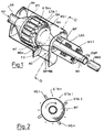
- FIG. 1 shows a part of an extruder ET, the screw tube SR in a multiple mouthpiece VM flows out, the numerous extruder outlet nozzles with each an outlet opening ETA1, ... ETAn.
- a plastic melt KU enters the screw tube Multiple - VM mouthpiece.
- From every outlet ETA1, ... ETAn enters a strand of melted, but after immediately freezing plastic strand.
- the plastic strand is formed before it solidifies completely chopped; the small cut pieces solidify to granules GR. Is known and beneficial it, the plastic strand at a speed of about 0.2 m / s to 0.6 m / s from the extruder outlet openings ETA1, ... to let ETAn emerge.
- a cutting tool MK consisting of an annular one Knife holder MT with peripherally arranged knives MS1, ... MSn can be rotated axially in front of the front wall of the Multiple mouthpiece VM arranged that the knife MS Swipe past the extruder orifices. This is also shown in Fig. 2.
- the ring-shaped knife carrier MT forms the end edge a funnel-shaped opening TO, with which it is in one piece and is rotatably connected.
- the opening TO in turn converges to a water supply line WF, which as Rotor element is mounted in a housing.
- WF water supply line
- the water supply line WF protrudes from the Housing is out via a rotary seal (not shown) waterproof with a water connection line WAE connected.
- a rotary seal not shown
- the knives MS1, ... MSn and the emerging plastic strand are cooled by the water.
- the end of the water supply line is particularly spectacular WF a funnel-shaped opening Shape.
- the funnel opening widens towards the cutting tool MK off, i.e. the water supply line WF ends similar to a trumpet.
- the walls of the water supply pipe can also from the Water exclusion line to the knives MS1, ... MSn cross section like a truncated cone.
- the funnel-shaped Extended opening TO of the water supply line WF and their rapid rotation about an axis AH with about 1000 up to 4000 U / min the water WA to the Flows inside the funnel-shaped opening, because a centrifugal force acts.
- Water WA superimposed on a swirl flow The water WA therefore strikes with considerable turbulence with tangential Component on the knives MS1, ... MSn and on the plastic strands. It cools the aforementioned Elements and wash the resulting granules through the between knife carrier MT and end wall SW Gap to the outside.
- the water supply line WF rotates in bearings LAG; their speed can be controlled by an ANT drive being controlled.
- an electric motor For example, a hydraulic motor or a water turbine drive can be used.
Landscapes
- Engineering & Computer Science (AREA)
- Mechanical Engineering (AREA)
- Manufacturing & Machinery (AREA)
- Processing And Handling Of Plastics And Other Materials For Molding In General (AREA)
Abstract
Description
Die Erfindung betrifft eine Vorrichtung zum Granulieren von Kunststoffen, aufweisend
- ein Schneidwerkzeug, das die aus Austrittsöffnungen eines Extruders austretenden Stränge des Kunststoffes granuliert,
- eine Zuführungsleitung für Wasser als Kühlmedium, das
das Schneidwerkzeug und die austretenden Stränge des
Kunststoffes kühlt,
wobei die Zuführungsleitung zum Schneidwerkzeug innerhalb einer trichterförmigen Erweiterung vor dem Schneidwerk endet,
wobei das Schneidwerkzeug ein ringförmiger Messerträger mit Messern ist und der Messerträger den Abschlußrand der trichterförmigen Erweiterung ausbildet, und
wobei das Wasser zugleich Transportmedium für das abgeschlagene Granulat ist, und - eine Austrittsöffnung für Granulat und Wasser.
- a cutting tool that granulates the strands of plastic emerging from the outlet openings of an extruder,
- a supply line for water as a cooling medium, which cools the cutting tool and the emerging strands of the plastic,
the feed line to the cutting tool ending within a funnel-shaped extension in front of the cutting device,
wherein the cutting tool is an annular knife carrier with knives and the knife carrier forms the end edge of the funnel-shaped extension, and
wherein the water is also a transport medium for the chopped off granulate, and - an outlet for granules and water.
Eine Vorrichtung der eingangs genannten Art ist aus der US-A-4 300 877 bekannt. Sie besteht aus einem Trägerkörper besteht, der an seiner Außenseite Austrittsöffnungen aufweist. Die Austrittsöffnungen sind mit Zuführungskanälen für den Durchfluß von flüssigem Kunststoff verbunden, der einen Hohlkörper trägt. Er besteht aus einem hohlzylindrischen Stil, der in einen Trichter übergeht. Im Trichter ist eine Platte mit segmentförmigen Ausnehmungen angeordnet, die auf die Welle geschraubt ist. Der Trichter geht an seinem Rand in eine Ringscheibe über, auf der Schneidmesser angeordnet sind. Der hohlzylindrische Stil des Hohlkörpers rotiert um eine statisch angeordnete Wasserzuführungsleitung.A device of the type mentioned is from the US-A-4,300,877. It consists of a carrier body exists, the outlet openings on its outside having. The outlet openings are with Feed channels for the flow of liquid Connected plastic that carries a hollow body. He consists of a hollow cylindrical style that fits into one Funnel passes. There is a plate in the funnel segment-shaped recesses arranged on the Shaft is screwed. The funnel goes to its edge into an washer, on the cutting knife are arranged. The hollow cylindrical style of the hollow body rotates around a statically arranged water supply line.
Nachteilig ist, daß in der Platte Zwischenstege zwischen den segmentförmigen Ausnehmungen angeordnet sind und der hohlzylindrische Stil um die Eingangsleitung rotiert. Dadurch trifft über die Eingangsleitung das axillar eintretende Wasser gegen das Zentrum der Platte. Nur ein Teil des Wassers wird durch die Segmente hindurchgelassen und büßt damit an Kühlwirkung für die Schneidmesser und an Transportwirkung gegenüber dem abgeschlagenen Granulat ein. Die Stege zwischen den Segmenten verursachen einen weiteren Wirkungsverlust, indem sie den seitwärtigen Wasserstrom bei einer Rotation des Hohlkörpers ständig unterbrechen.The disadvantage is that in the plate intermediate webs between the segment-shaped recesses are arranged and the hollow cylindrical style rotates around the input pipe. As a result, the axillary hits via the input line entering water towards the center of the plate. Just one Part of the water is let through the segments and thus loses cooling effect for the cutting knives and transport effect compared to the knocked off Granules. The webs between the segments cause another loss of effectiveness by the sideways water flow when the Always interrupt the hollow body.
Aus der CH-A-530 852 ist ein Granulator für eine Trockengranulierung bekannt, bei dem vor einer Sieblochplatte Schneidmesser rotieren. Die Schneidmesser sind an einer Scheibe eines Schneidkörpers befestigt, der trichterförmig ausgebildet ist und vor einem zylinderförmigen Ausgangsrohr rotiert, das auf einem ortfesten Gehäuseteil befestigt ist. Die Scheibe des Schneidkopfes weist im Bereich der Schneidmesser je einen Ausgangsschlitz auf.CH-A-530 852 describes a granulator for dry granulation known, in front of a perforated plate Rotate cutting knife. The cutting knives are on one Disk of a cutting body attached, the funnel-shaped is formed and in front of a cylindrical Output tube rotates on a stationary housing part is attached. The disc of the cutting head faces one exit slot each in the area of the cutting knives on.
Der Schneidkörper ist allerdings nur deshalb trichterförmig ausgebildet, damit das durch das Ausgangsrohr angesaugte Granulat gesammelt wird. Darüberhinaus wird die Saug- und Kühlwirkung durch die Scheibe und die in ihr vor den Schneidmessern eingebrachten Schlitze gemindert. Die Rotation der Scheibe und die der Schneidmesser wirkt der Saugwirkung des Luftstromes ebenfalls entgegen. Hierdurch besteht die Gefahr, daß sich das Granulat in dem Schlitz festsetzen kann und die Saug- und Kühlwirkung weiter herabgesetzt wird.However, the cutting body is only funnel-shaped for this reason trained so that through the exit pipe sucked granules is collected. Furthermore, the suction and cooling effect through the disc and the in her slots in front of the cutting knives diminished. The rotation of the disc and that of the cutting knife also affects the suction effect of the air flow opposite. This creates the risk that the Granules can set in the slot and the suction and Cooling effect is further reduced.
In DE-B-2 646 309 wird eine Granuliervorrichtung für thermoplastische Kunststoffe, die auf einem rotierenden Schneidwerkzeug besteht, das direkt vor Extruderöffnungen rotiert und aus einem Extruder austretende Stränge eines Kunststoffes abschlägt, beschrieben. Mit einer unten am Gehäuse des Granulatorgehäuses angeordneten Zuführung wird Wasser zum Kühlen des Schneidwerkzeuges zugeführt. Die Ausleitung des Wassers, das zugleich Transportmedium für das abgeschlagene Granulat ist, erfolgt nach oben über eine Austrittsöffnung zu einem Granulatabschneider. Dadurch, daß die Strömung von der Wasserzufuhr zu Austrittsöffnungen von Granulat und Wasser zum einen nicht mit der Kunststoff-Führung übereinstimmt und zum anderen gegen die Schwerkraft gerichtet ist, kann es zu Störungen im Granulieren und beim Abtransport kommen.DE-B-2 646 309 describes a granulating device for thermoplastics rotating on a Cutting tool exists, which is directly in front of extruder openings rotates and emerges from an extruder Strands of a plastic hitting described. With one arranged at the bottom of the housing of the granulator housing Water is used to cool the cutting tool fed. The drainage of the water at the same time transport medium for the chipped granulate is upwards via an outlet opening a granule cutter. The fact that the flow of the water supply to the outlet openings of the granulate and Water, on the one hand, not with the plastic guide agrees and secondly against gravity is directed, it can lead to disturbances in the granulation and come when they are transported.
Aus der DE-A-1 454 863 ist eine Vorrichtung zum Schneiden, Kühlen und Wegtransport eines Granulats bekannt. Stränge aus plastischem Kunststoff, die aus einer gelochten Extruderplatte austreten, werden von einem Schneidwerkzeug abgeschlagen. Die gerade Welle für den Messerantrieb ist hohl ausgeführt und an gebogene Rohre angeschlossen, die an den Messern enden. Durch diese Rohre wird das in den Messerarm eintretende Granulat mit Wasserspülung wegtransportiert. Unten am schneckenartig ausgeführten Gehäuse ist eine Öffnung angebracht, durch die das Wasser und das Granulat abgeleitet werden. Auch wenn das Granulieren, Kühlen und der Abtransport des Wasser- und Granulatgemisches einer befriedigenden Lösung zugeführt sind, wird die Vorrichtung durch die beschränkte Anzahl von Austrittsöffnungen aus einer gelochten Extruderplatte in ihrer Kapazität begrenzt. Darüber hinaus ist das Anbringen der gebogenen Rohre kompliziert. Nur mit großem Aufwand sind die Unwuchten beherrschbar, die durch das aus dem Rohr herausgeschleuderte Wasser entstehen können. Außerdem kann die direkte Zuführung des Kühlmittels an die Kunststoffaustrittsöffnungen zu einer solchen Abkühlung führen, daß die Kunststoffstränge in der Düsenführung erstarren.DE-A-1 454 863 describes a device for cutting, Cooling and transport of granules known. Strands of plastic that are perforated from a plastic Extruder plate emerge from one Cutting tool knocked off. The straight wave for that Knife drive is hollow and on bent tubes connected, which end at the knives. Through this The granules entering the knife arm become part of the pipes Water flush transported away. Down at snail-like executed housing is provided through an opening which drain the water and the granules. Also if the granulation, cooling and removal of the A satisfactory mixture of water and granules Solution are supplied, the device is through the limited number of outlet openings from one perforated extruder plate limited in capacity. In addition, attaching the bent pipes complicated. The unbalances are only with great effort manageable, which by thrown out of the tube Water can arise. In addition, the direct supply of the coolant to the plastic outlet openings lead to such a cooling, that the plastic strands solidify in the nozzle guide.
Weiterhin ist aus der DE-A 3 212 409 eine Vorrichtung bekannt, die einen Extruder mit einem von Heizkörpern umgebenen Zylinder enthält, der vorn in einer runden Platte mit Düsenöffnungen endet. Vor den Düsenöffnungen rotieren eine mit einer Hohlwelle verbundene Schneidscheibe, deren Schneidklingen Kühlwasseraustrittsöffnungen aufweisen. Durch das Erwärmen des Kunststoffes wird zwar ein Erstarren verhindert, aber das von der Schneidklinge auf die Düsenöffnung tretende Wasser drückt das Granulat auf die Platte, wodurch dessen Abfluß und die des Wasser- und Granulatgemisches behindert wird.Furthermore, DE-A 3 212 409 describes a device known an extruder with one of radiators contains the surrounding cylinder, the front in a round Plate with nozzle openings ends. In front of the nozzle openings rotate a cutting disc connected to a hollow shaft, their cutting blades cooling water outlet openings exhibit. By heating the plastic solidification is prevented, but by the cutting blade water that presses on the nozzle opening presses this Granules on the plate, causing its drain and the of the water and granulate mixture is hindered.
Der Erfindung liegt die Aufgabe zugrunde, eine Vorrichtung zum Granulieren von Kunststoff der eingangs genannten Art so weiter zu entwickeln, daß das Schneidwerkzeug ausreichend gekühlt, der Kunststoff ohne Behinderung granuliert und das Gemisch aus Granulat und Wasser einfach abtransportiert wird.The invention has for its object a device for granulating plastic at the beginning to develop the type mentioned so that the Sufficiently cooled cutting tool, the plastic without Disability granulated and the mixture of granules and Water is simply transported away.
Erreicht wird dieses Ziel dadurch,
- daß ein Teil der Zuführungsleitung in die trichterförmige Erweiterung übergeht und um eine Achse drehbar angeordnet ist und
- daß die Messer über den Abschlußrand der trichterförmigen Erweiterung herausragend angeordnet sind.
- that part of the feed line merges into the funnel-shaped extension and is rotatably arranged about an axis and
- that the knives are arranged projecting over the end of the funnel-shaped extension.
Die mit der Erfindung erzielten Vorteile bestehen insbesondere darin, daß das in die Wasserzuführung eintretende Wasser zu seiner Längsströmung einen Drall erfährt. Dieser Drall wird immer größer, je näher das Wasser dem Schneidwerkzeug kommt. Erhöht wird dieser Effekt noch durch den sich vergrößernden Durchmesser des Trichters, so daß sich das Wasser beinahe nur außenseitig bewegt. Durch diese Wasserbewegung wird das Schneidwerkzeug gekühlt, ohne daß dabei der Kunststoff erstarrt. Außerdem werden die austretenden Kunststoffstränge leicht nach außen gebogen und das Granulat mit dem Wasser bei Unterstützung durch das Schneidwerkzeug nach außen geschleudert. Das an der außenliegenden Wand des Extruders abfließende Gemisch behindert so in keiner Weise den Bereich zwischen Austrittsöffnung und Schneidwerkzeug.The advantages achieved with the invention are in particular in that what enters the water supply Water swirls to its longitudinal flow. This twist gets bigger the closer the water is to that Cutting tool is coming. This effect is increased due to the increasing diameter of the funnel, so that the water almost only moves on the outside. Through this water movement, the cutting tool cooled without the plastic solidifying. In addition, the emerging plastic strands slightly bent outwards and the granules with the Water with the help of the cutting tool hurled outside. That on the outside wall of the Extruder flowing mixture does not hinder in any way Way the area between outlet and Cutting tool.
Es ist darüber hinaus vorteilhaft die Austrittsöffnungen für das Wasser-Granulat-Gemisch im Bereich zum Schneidwerkzeug anzuordnen. Dadurch können Granulat und Wasser unter Ausnutzung der Schwerkraft schnellstens abfließen. Ihre Austrittsöffnung sollte dabei in dem unteren Punkt des Gehäuses angebracht werden, der strömungstechnisch am günstigsten ist. Das kann zur Folge haben, daß die Austrittsöffnung nicht genau lotrecht unter der Rotationsachse zwischen Wassereintrittsöffnung und Schneidwerkzeug angeordnet ist.The outlet openings are also advantageous for the water-granulate mixture in the area of the cutting tool to arrange. This can cause granules and water drain as quickly as possible using gravity. Your outlet opening should be in the lower point be attached to the housing, the fluidic is cheapest. As a result, the The outlet opening is not exactly perpendicular to the Rotation axis between water inlet opening and Cutting tool is arranged.
Die Erfindung wird nachstehend an einem Ausführungsbeispiel näher erläutert. In der Zeichnung zeigen in
- Figur 1:
- Eine Vorrichtung zum Granulieren von Kunststoff in einer teilgeschnittenen, perspektivischen, schematischen Darstellung,
- Figur 2:
- Einen Schnitt durch eine Vorrichtung gemäß Figur 1 entlang der Linie II - II.
- Figure 1:
- A device for granulating plastic in a partially cut, perspective, schematic representation,
- Figure 2:
- A section through a device according to Figure 1 along the line II - II.
In Fig. 1 ist ein Teil eines Extruders ET dargestellt, dessen Schneckenrohr SR in ein Vielfach-Mundstück VM einmündet, das zahlreiche Extruderaustrittsdüsen mit je einer Austrittsöffnung ETA1, ... ETAn trägt. Aus dem Schneckenrohr tritt eine Kunststoff-Schmelze KU in das Vielfach--Mundstück VM ein. Aus jeder Austrittsöffnung ETA1, ... ETAn tritt ein Strang geschmolzener, aber nach dem Austreten sofort erstarrender Kunststoffstrang aus. Vor dem vollständigen Erstarren wird der Kunststoffstrang gehäckselt; die kleinen geschnittenen Stücke erstarren zu Granulat GR. Bekannt und vorteilhaft ist es, den Kunststoffstrang mit einer Geschwindigkeit von etwa 0,2 m/s bis 0,6 m/s aus den Extruderaustrittsöffnungen ETA1, ... ETAn austreten zu lassen.1 shows a part of an extruder ET, the screw tube SR in a multiple mouthpiece VM flows out, the numerous extruder outlet nozzles with each an outlet opening ETA1, ... ETAn. From the A plastic melt KU enters the screw tube Multiple - VM mouthpiece. From every outlet ETA1, ... ETAn enters a strand of melted, but after immediately freezing plastic strand. The plastic strand is formed before it solidifies completely chopped; the small cut pieces solidify to granules GR. Is known and beneficial it, the plastic strand at a speed of about 0.2 m / s to 0.6 m / s from the extruder outlet openings ETA1, ... to let ETAn emerge.
Ein Schneidwerkzeug MK, bestehend aus einem ringförmigen Messerträger MT mit peripher angeordneten Messern MS1, ... MSn ist so axial rotierbar vor der Stirnwand des Vielfach-Mundstückes VM angeordnet, daß die Messer MS unmittelbar vor den Extruderaustrittsöffnungen vorbeistreichen. Dies ist auch in Fig. 2 dargestellt.A cutting tool MK consisting of an annular one Knife holder MT with peripherally arranged knives MS1, ... MSn can be rotated axially in front of the front wall of the Multiple mouthpiece VM arranged that the knife MS Swipe past the extruder orifices. This is also shown in Fig. 2.
Der ringförmige Messerträger MT bildet den Abschlußrand einer trichterförmigen Öffnung TO, mit der er einstückig und rotierbar verbunden ist. Die Öffnung TO wiederum konvergiert zu einer Wasserzuführungsleitung WF, die als Rotorelement in einem Gehäuse gelagert ist. Am Ende EWF der Wasserzuführungsleitung WF ragt diese aus dem Gehäuse heraus ist über eine Drehdichtung (nicht dargestellt) wasserdicht mit einer Wasseranschlußleitung WAE verbunden. Von der Wasseranschlußleitung WAE kommend kann Kühl- und Spülwasser bis zur Öffnung TO geführt werden.The ring-shaped knife carrier MT forms the end edge a funnel-shaped opening TO, with which it is in one piece and is rotatably connected. The opening TO in turn converges to a water supply line WF, which as Rotor element is mounted in a housing. At the end of EWF the water supply line WF protrudes from the Housing is out via a rotary seal (not shown) waterproof with a water connection line WAE connected. Coming from the water supply line WAE can run cooling and rinsing water up to the opening TO will.
Die Messer MS1, ... MSn und der austretende Kunststoffstrang werden durch das Wasser gekühlt. Wie die Fig. 1 besonders deutlich zeugt, hat das Ende der Wasserzuführungsleitung WF eine trichterförmig sich öffnende Gestalt. Die Trichteröffnung weitet sich zum Schneidwerkzeug MK aus, d.h., die Wasserzuführungsleitung WF endet ähnlich wie bei einer Trompete. Die Wände der Wasserzuführungsleitung können aber auch von der Wasserausschlußleitung zu den Messern MS1, ... MSn hin im Querschnitt wie eine Kegelstumpf ausgeführt werden.The knives MS1, ... MSn and the emerging plastic strand are cooled by the water. Like FIG. 1 The end of the water supply line is particularly impressive WF a funnel-shaped opening Shape. The funnel opening widens towards the cutting tool MK off, i.e. the water supply line WF ends similar to a trumpet. The walls of the water supply pipe can also from the Water exclusion line to the knives MS1, ... MSn cross section like a truncated cone.
Erfindungswesentlich ist, daß durch die trichterförmig erweiterte Öffnung TO der Wasserzuführungsleitung WF und ihre schnelle Rotation um eine Achse AH mit etwa 1000 bis 4000 U/min das Wasser WA im wesentlichen an den Innenwänden der trichterförmigen Öffnung entlangströmt, da eine Zentrifugalkraft wirkt. Gleichzeitig wird dem Wasser WA eine Drallströmung überlagert. Das Wasser WA trifft demnach mit erheblicher Turbulenz mit tangentialer Komponente auf die Messer MS1, ... MSn und auf die Kunststoffstränge. Es kühlt die vorgenannten Elemente und schwemmt das entstandene Granulat durch den zwischen Messerträger MT und Stirnwand SW liegenden Spalt nach außen.It is essential to the invention that the funnel-shaped Extended opening TO of the water supply line WF and their rapid rotation about an axis AH with about 1000 up to 4000 U / min the water WA to the Flows inside the funnel-shaped opening, because a centrifugal force acts. At the same time Water WA superimposed on a swirl flow. The water WA therefore strikes with considerable turbulence with tangential Component on the knives MS1, ... MSn and on the plastic strands. It cools the aforementioned Elements and wash the resulting granules through the between knife carrier MT and end wall SW Gap to the outside.
Die Wasserzuführungsleitung WF dreht sich dabei in Lagerungen LAG; ihre Drehzahl kann über einen Antrieb ANT gesteuert werden. Anstelle eines elektromotorischen Antriebs kann beispielsweise auch ein Hydromotor oder ein Wasser-Turbinenantrieb verwendet werden.The water supply line WF rotates in bearings LAG; their speed can be controlled by an ANT drive being controlled. Instead of an electric motor For example, a hydraulic motor or a water turbine drive can be used.
Das in die Wasserzuführungsleitung WF axial einströmende Wasser WA erhält durch starke Rotation der trichterförmigen Öffnung TO eine zusätzliche rotierende Bewegungskomponente. Je weiter das Wasser WA in Richtung des Schneidwerkzeuges MK fließt, umso stärker wird diese. Das hat zur Folge, daß das Wasser WA letztendlich mit starker, nach außen fließender Strömung auf die Messer MS1, ... MSn des Schneidwerkzeuges MK trifft. Dadurch wird jedes einzelne Messer MS1, ... MSn ausreichend gekühlt. Darüber hinaus wird der aus der Extruderaustrittsdüse ETA1, ... ETAn austretende Kunststoffstrang kraftvoll mit Wasser WA nach außen gedrückt. Die Schneidbahn wird dadurch immer frei gehalten von geschnittenem Granulat GR.The axially flowing into the water supply line WF Water WA is obtained by strong rotation of the funnel-shaped Opening TO an additional rotating movement component. The further the water WA towards the Cutting tool MK flows, the stronger it becomes. As a result, the water WA ultimately with strong, outward flowing flow on the knives MS1, ... MSn of the cutting tool MK hits. Thereby every single knife MS1, ... MSn is sufficient chilled. In addition, the extruder outlet nozzle ETA1, ... ETAn emerging plastic strand forcefully pressed outwards with water WA. The cutting path is always kept free of cut Granules GR.
Mit der Richtungsänderung des Wassers wird also ein doppelter Effekt erreicht. Zum einen werden die Messer MS1, ... MSn ausreichend gekühlt, ohne daß dabei der aus den Extruderaustrittsdüsen austretende Kunststoff KU innerhalb der Extruderöffnungen erstarrt; zum anderen wird der Bereich vor den Extruderaustrittsöffnungen ETA1, ... ETAn immer frei von Kunststoff, insbesondere Granulat GR gehalten.With the change of direction of the water becomes a double effect achieved. Firstly, the knives MS1, ... MSn sufficiently cooled without the plastic KU emerging from the extruder outlet nozzles solidified within the extruder openings; on the other hand becomes the area in front of the extruder outlet openings ETA1, ... ETAn always free of plastic, in particular Granules GR held.
Die rotierenden Messer MS1, ... MSn des Schneidwerkzeuges MK und das rotierend strömende Wasser WA sorgen dafür, daß das Granulat GR schnell aus diesem Bereich weggefördert wird. Vorteilhaft wirkt sich dabei aus, daß das heruntergeschwemmte Gemisch aus Granulat GR und Wasser WA aus einer Austrittsöffnung AO abfließen kann. Diese Austrittsöffnung AO sollte, um besser wirksam zu sein, nicht genau senkrecht unter der Achse AH angeordnet sein.The rotating knives MS1, ... MSn of the cutting tool MK and the rotating water WA making sure that the granules GR quickly out of this area is promoted away. The fact that the washed down mixture of granules GR and Water WA can flow out of an outlet opening AO. This exit opening AO should, in order to be more effective be, not exactly perpendicular under the axis AH be arranged.
Claims (3)
- An apparatus for granulating plastics materials, comprising:a cutting tool (MK) which granulates the strands of the plastics material (KU) which emerge from exit openings (ETA1, ... ETAn) of an extruder (ET),a feed line for water (WA) as cooling medium which cools the cutting tool (MK) and the emerging strands of the plastics material (KU), the feed line (WF) to the cutting tool (MK) ending within a funnel-shaped widened section before the cutting tool (MK),
the cutting tool (MK) being an annular knife holder (MT) with knives (MS1, ... MSn) and the knife holder (MT) forming the terminal edge of the funnel-shaped widened section (TO), and the water (WA) at the same time being the transport medium for the granules (GR) knocked off, andan exit opening (AO) for granules and water (GR + WA),
characterised in thatpart of the feed line (WF) merges into the funnel-shaped widened section (TO) and is arranged to rotate about an axis (AH) andthat the knives (MS1, ... MSn) are arranged projecting beyond the terminal edge of the funnel-shaped widened section (TO). - An apparatus according to Claim 1, characterised in that the funnel-shaped widened section (TO) of the feed line (WF) has a truncated cone-like and/or trumpet-like shape.
- An apparatus according to Claim 1 or 2, characterised in that the exit opening (AO) for the granule/water mixture is located beneath the gap between the end of the feed line (WF) and the outside of the cutting tool (MK).
Applications Claiming Priority (3)
| Application Number | Priority Date | Filing Date | Title |
|---|---|---|---|
| DE9210621U DE9210621U1 (en) | 1992-08-08 | 1992-08-08 | Device for granulating plastics |
| DE9210621U | 1992-08-08 | ||
| PCT/EP1993/002021 WO1994003314A1 (en) | 1992-08-08 | 1993-07-29 | Device for granulating plastics |
Publications (2)
| Publication Number | Publication Date |
|---|---|
| EP0607399A1 EP0607399A1 (en) | 1994-07-27 |
| EP0607399B1 true EP0607399B1 (en) | 1998-01-07 |
Family
ID=6882472
Family Applications (1)
| Application Number | Title | Priority Date | Filing Date |
|---|---|---|---|
| EP93917689A Expired - Lifetime EP0607399B1 (en) | 1992-08-08 | 1993-07-29 | Device for granulating plastics |
Country Status (3)
| Country | Link |
|---|---|
| EP (1) | EP0607399B1 (en) |
| DE (2) | DE9210621U1 (en) |
| WO (1) | WO1994003314A1 (en) |
Families Citing this family (1)
| Publication number | Priority date | Publication date | Assignee | Title |
|---|---|---|---|---|
| DE102013018239A1 (en) | 2013-10-30 | 2015-04-30 | Automatik Plastics Machinery Gmbh | Granulating device with cutting blade head |
Family Cites Families (6)
| Publication number | Priority date | Publication date | Assignee | Title |
|---|---|---|---|---|
| DE1454863A1 (en) * | 1963-08-30 | 1969-04-30 | Reifenhaeuser Kg | Device for cutting, cooling and transporting away granules |
| CH460319A (en) * | 1967-02-03 | 1968-07-31 | Barmag Barmer Maschf | Device for granulating thermoplastic polymeric material |
| CH530852A (en) * | 1972-04-19 | 1972-11-30 | Stuedli Hans | Dry granulator - with multi blade cutter head and suction extraction for plastic granule prodn |
| DE2646309C3 (en) * | 1976-10-14 | 1980-02-21 | Werner & Pfleiderer, 7000 Stuttgart | Underwater pelletizing device for thermoplastics |
| US4300877A (en) * | 1979-01-10 | 1981-11-17 | Sterling Extruder Corp. | Underwater pelletizer |
| DE3212409A1 (en) * | 1982-04-02 | 1983-10-13 | Kensaku Matsubara Osaka Nakamura | Plastics pelleting machine |
-
1992
- 1992-08-08 DE DE9210621U patent/DE9210621U1/en not_active Expired - Lifetime
-
1993
- 1993-07-29 WO PCT/EP1993/002021 patent/WO1994003314A1/en active IP Right Grant
- 1993-07-29 EP EP93917689A patent/EP0607399B1/en not_active Expired - Lifetime
- 1993-07-29 DE DE59307942T patent/DE59307942D1/en not_active Expired - Fee Related
Also Published As
| Publication number | Publication date |
|---|---|
| DE9210621U1 (en) | 1992-10-15 |
| DE59307942D1 (en) | 1998-02-12 |
| EP0607399A1 (en) | 1994-07-27 |
| WO1994003314A1 (en) | 1994-02-17 |
Similar Documents
| Publication | Publication Date | Title |
|---|---|---|
| DE2646309A1 (en) | UNDERWATER GRANULATING DEVICE | |
| DE19914116C2 (en) | Underwater pelletizer and process for pelletizing thermoplastics | |
| DE3541500C2 (en) | ||
| EP1618947A1 (en) | Cutting device for tough plastic materials and method for operating such a cutting device | |
| EP0046569A2 (en) | Process and apparatus for mixing solids with liquids | |
| EP3062978B1 (en) | Granulating device with cutting knife head | |
| WO2015082069A1 (en) | Process for producing particles of granulated material from a molten material | |
| EP0764075A1 (en) | Hot-chopping granulation device | |
| DE1454888B2 (en) | DEVICE FOR PELLETIZING THERMOPLASTIC PLASTICS | |
| EP0229610B1 (en) | Apparatus for granulation of thermoplastic strands | |
| DE3009185C2 (en) | Device for melting and mixing thermoplastic materials | |
| EP0607399B1 (en) | Device for granulating plastics | |
| DE2328019B2 (en) | PELLETIZING DEVICE FOR PLASTICS | |
| EP1412150B1 (en) | Device for granulating a thermoplastic, which is extruded from nozzles | |
| AT507066B1 (en) | DEVICE FOR GRANULATING PLASTIC | |
| DE2813332A1 (en) | Thermoplastic strand granulator - with side stream of coolant on perforated plate, revolving flow removing cut granules | |
| DE19631182A1 (en) | Granulating extruder, especially for plastics and foodstuffs | |
| EP0862944A1 (en) | Process and apparatus for making pallets from product strands | |
| DE3116117C2 (en) | Device for granulating plastic melts and other plastic masses | |
| DE3116153C2 (en) | Device for granulating plastic melts and other plastic masses | |
| DE2825287A1 (en) | DEVICE FOR GRANULATING PLASTIC MELT | |
| DE1454753B2 (en) | PELLETIZER FOR PLASTIC BULK | |
| DE1454863A1 (en) | Device for cutting, cooling and transporting away granules | |
| DE102013020317A1 (en) | Apparatus and method for granulating melt material | |
| EP4041515B1 (en) | Assembly for granulating extruded material |
Legal Events
| Date | Code | Title | Description |
|---|---|---|---|
| PUAI | Public reference made under article 153(3) epc to a published international application that has entered the european phase |
Free format text: ORIGINAL CODE: 0009012 |
|
| AK | Designated contracting states |
Kind code of ref document: A1 Designated state(s): DE FR GB IT NL |
|
| 17P | Request for examination filed |
Effective date: 19940701 |
|
| 17Q | First examination report despatched |
Effective date: 19950706 |
|
| GRAG | Despatch of communication of intention to grant |
Free format text: ORIGINAL CODE: EPIDOS AGRA |
|
| GRAG | Despatch of communication of intention to grant |
Free format text: ORIGINAL CODE: EPIDOS AGRA |
|
| GRAH | Despatch of communication of intention to grant a patent |
Free format text: ORIGINAL CODE: EPIDOS IGRA |
|
| GRAH | Despatch of communication of intention to grant a patent |
Free format text: ORIGINAL CODE: EPIDOS IGRA |
|
| GRAA | (expected) grant |
Free format text: ORIGINAL CODE: 0009210 |
|
| AK | Designated contracting states |
Kind code of ref document: B1 Designated state(s): DE FR GB IT NL |
|
| REF | Corresponds to: |
Ref document number: 59307942 Country of ref document: DE Date of ref document: 19980212 |
|
| GBT | Gb: translation of ep patent filed (gb section 77(6)(a)/1977) |
Effective date: 19980219 |
|
| ITF | It: translation for a ep patent filed | ||
| ET | Fr: translation filed | ||
| PLBE | No opposition filed within time limit |
Free format text: ORIGINAL CODE: 0009261 |
|
| STAA | Information on the status of an ep patent application or granted ep patent |
Free format text: STATUS: NO OPPOSITION FILED WITHIN TIME LIMIT |
|
| 26N | No opposition filed | ||
| REG | Reference to a national code |
Ref country code: GB Ref legal event code: IF02 |
|
| PGFP | Annual fee paid to national office [announced via postgrant information from national office to epo] |
Ref country code: NL Payment date: 20020731 Year of fee payment: 10 |
|
| PGFP | Annual fee paid to national office [announced via postgrant information from national office to epo] |
Ref country code: GB Payment date: 20020814 Year of fee payment: 10 |
|
| PGFP | Annual fee paid to national office [announced via postgrant information from national office to epo] |
Ref country code: FR Payment date: 20020819 Year of fee payment: 10 |
|
| PG25 | Lapsed in a contracting state [announced via postgrant information from national office to epo] |
Ref country code: GB Free format text: LAPSE BECAUSE OF NON-PAYMENT OF DUE FEES Effective date: 20030729 |
|
| PG25 | Lapsed in a contracting state [announced via postgrant information from national office to epo] |
Ref country code: NL Free format text: LAPSE BECAUSE OF NON-PAYMENT OF DUE FEES Effective date: 20040201 |
|
| GBPC | Gb: european patent ceased through non-payment of renewal fee |
Effective date: 20030729 |
|
| PG25 | Lapsed in a contracting state [announced via postgrant information from national office to epo] |
Ref country code: FR Free format text: LAPSE BECAUSE OF NON-PAYMENT OF DUE FEES Effective date: 20040331 |
|
| NLV4 | Nl: lapsed or anulled due to non-payment of the annual fee |
Effective date: 20040201 |
|
| REG | Reference to a national code |
Ref country code: FR Ref legal event code: ST |
|
| PG25 | Lapsed in a contracting state [announced via postgrant information from national office to epo] |
Ref country code: IT Free format text: LAPSE BECAUSE OF NON-PAYMENT OF DUE FEES Effective date: 20050729 |
|
| PGFP | Annual fee paid to national office [announced via postgrant information from national office to epo] |
Ref country code: DE Payment date: 20071113 Year of fee payment: 15 |
|
| PG25 | Lapsed in a contracting state [announced via postgrant information from national office to epo] |
Ref country code: DE Free format text: LAPSE BECAUSE OF NON-PAYMENT OF DUE FEES Effective date: 20090203 |