EP0606874B1 - Method and apparatus for preventing air entry between a moving material web and a roll - Google Patents
Method and apparatus for preventing air entry between a moving material web and a roll Download PDFInfo
- Publication number
- EP0606874B1 EP0606874B1 EP94100259A EP94100259A EP0606874B1 EP 0606874 B1 EP0606874 B1 EP 0606874B1 EP 94100259 A EP94100259 A EP 94100259A EP 94100259 A EP94100259 A EP 94100259A EP 0606874 B1 EP0606874 B1 EP 0606874B1
- Authority
- EP
- European Patent Office
- Prior art keywords
- web
- backing roll
- pressing
- roll
- line
- Prior art date
- Legal status (The legal status is an assumption and is not a legal conclusion. Google has not performed a legal analysis and makes no representation as to the accuracy of the status listed.)
- Expired - Lifetime
Links
Images

Classifications
-
- D—TEXTILES; PAPER
- D21—PAPER-MAKING; PRODUCTION OF CELLULOSE
- D21H—PULP COMPOSITIONS; PREPARATION THEREOF NOT COVERED BY SUBCLASSES D21C OR D21D; IMPREGNATING OR COATING OF PAPER; TREATMENT OF FINISHED PAPER NOT COVERED BY CLASS B31 OR SUBCLASS D21G; PAPER NOT OTHERWISE PROVIDED FOR
- D21H23/00—Processes or apparatus for adding material to the pulp or to the paper
- D21H23/02—Processes or apparatus for adding material to the pulp or to the paper characterised by the manner in which substances are added
- D21H23/22—Addition to the formed paper
- D21H23/30—Pretreatment of the paper
Definitions
- the present invention relates to a method according to the preamble of claim 1 for preventing air conveyed by a moving material web from entering between a backing roll of a coater and said web.
- the invention further concerns an apparatus according to the preamble of claim 8 for implementing said method.
- the kiss roll is ordinarily rotated along with the web at a tangential speed of approx. 10 - 30 % of the speed of the web being coated.
- the kiss roll can be rotated counter to the web movement or at a different speed, whereby similar problems are met also in these cases. Air conveyed into the tapering space between the roll and the web causes equivalent complications in other application methods, too.
- the rotational speed of the kiss roll When the web speed is increased, the rotational speed of the kiss roll must be increased by an equivalent measure to avoid the occurrence of uncoated blotches. On the other hand, when the rotational speed of the kiss roll is increased, more splashing of the coat mix will occur, and eventually streaking of the coat, whereby the equipment and surroundings are soiled and paper quality deteriorated. Accordingly, a sufficiently low rotational speed of the kiss roll should be used that still can provide a coat of satisfactory quality. At maximum web speeds the rotational speed of the kiss roll unavoidably becomes so high as to cause splashing to a relatively high extent. Then, the rotational speed of the kiss roll need be reduced, which has not been possible in prior-art equipment due to the concomitant increase of coating defects.
- a feature that is present in all coating apparatuses as e. g. that of US-A-3 640 752 is that the web is pressed against the backing roll by the tension of the web itself.
- the web tension only is not at all sufficient to prevent the entry of air between the web and the backing roll.
- the tension of the web has to be relatively low since if the tension is increased, it will brake the web, especially thin paper webs.
- the web is wetted during the coating process and the wetting decreases the durability of the web, which naturally decreases the highest web tension that can be used. Since the web speeds of present coating apparatuses are very high, the web tension that would be required to prevent the entry of air between the web and the backing roll would certainly brake the web.
- the invention is based on pressing the web being coated against the backing roll from the opposite side of the web relative to the backing roll at a point preceding the nip between the kiss roll and the backing roll, whereby air is prevented from entering between the web and the backing roll.
- the invention offers significant benefits.
- the principal benefits of the invention are the quality improvement of coated paper and reduction of coating defects in most application methods.
- the rotational speed of the kiss roll can be reduced, whereby also the splashing of the coat mix is reduced, or alternatively, the web speed can be increased while still retaining the quality level unchanged.
- the assembly required is simple and easy to manufacture, and its retrofit compatibility with conventional coaters is good.
- the pressing of the web against the backing roll imposes no significant stress on the paper web thus causing no deterioration of the paper web properties, since the pressing operation can be arranged in a noncontacting manner. Additionally, the pressing means doctors away air conveyed by the web into the application nip or slit, thus equalizing the application conditions in the nip with a resulting improvement of the coat quality.
- FIG 1 shows diagrammatically one embodiment of the invention.
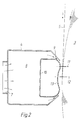
- Figure 2 shows an enlarged detail of the diagram of Fig. 1.
- a kiss roll 2 Located approximately to the midpoint of the arc covered by the web 5 over the backing roll 3 is a kiss roll 2 so as to form with the backing roll 3 an application nip through which the web 5 being coated passes.
- the kiss roll 2 is placed in a tray 1 containing so much coat mix 6 as to leave the nip of the roll 2 clearly above the coat mix level.
- the movement directions of the backing roll 3, the kiss roll 2 and the web 5 are indicated by arrows in the diagram.
- the entry of air between the backing roll 3 and the web 5 is prevented by means of a blow pipe 4.
- the pipe 4 is extended over the entire web width and has a slit nozzle mounted to it in the cross direction of the web, said pipe being mounted at the tangential meeting point of the web 5 with the backing roll 3 on the entry side of the web 5 relative to the kiss roll 2 in a manner described below in greater detail.
- the coating operation with the help of the above-described assembly is as follows.
- the web 5 meets first the backing roll 3 and the web is pressed by means of the air jet blown via the nozzle slit of the blow pipe 4 against the backing roll 3, thus preventing the air conveyed by the web 5 from entering between the web 5 and the backing roll 3.
- An appropriate gauge pressure at the meeting point of the web 5 with the backing roll 3 is approx. 2.5 kPa, whereby the entry of air under the web 5 is prevented at contemporary web speeds.
- the applied pressure is selected so as to make the imposed force sufficiently high to attain the desired effect of preventing the entry of the conveyed air between the web and the backing roll.
- the web 5 meets the kiss roll 2 whose rotation lifts coating mix 6 from the tray 1 to the nip between the web 5 and the kiss roll 2, and a portion of the mix is applied to the surface of the web 5 in the nip. Subsequently, the web 5 meets a doctor blade which is not shown here, since the doctor blade arrangements of a kiss roll coater are well known in the art.
- the blow pipe 4 is comprised of a U-shaped section extending at least essentially across the web 5, said section having the edges of the U-shape slightly inward slanted.
- the inside space of the section forms an air compartment 8 into which an inlet air nozzle 7 exits.
- a tubular flow guide 10 Adapted to the exit slit of the U-shaped section is a tubular flow guide 10 which blocks the exit slit almost entirely so as to leave only a narrow nozzle slit 9 between the perimeter of the tubular flow guide and either inward slanted edge of the section.
- the nozzle slit 9 is thus formed at either edge of the blow pipe 4 and said slits 9 direct the exiting air jets against each other toward the center plane 12 of the blow pipe 4.
- the perimeter of the tubular flow guide 10 facing the web 5 is curved so that its edges reach closer to the web 5, while its center is retracted from the web so as to form a groove 13.
- the purpose of the above-described contouring of the tubular flow guide 10 is to align the pressure effect of the air jets toward the center plane 12 of the blow pipe and to maximize the imposed pressure effect.
- the blow pipe 4 is placed at the meeting point of the web with the backing roll 3 so that the center plane 12 of the blow pipe, which determines the location where the pressure effect is applied, is situated next after the meeting point 11 of the web 5 with the roll 3 as viewed from the entry direction of the web 5 onto the roll.
- an advantageous displacement of the center plane 12 from the meeting point 11 is 8 - 12 mm, most advantageously 10 mm.
- the optimal placement of the blow pipe is dependent on the size of the backing roll 3, the web speed and other related factors, whereby the mounting of the blow pipe 4 is preferably arranged by adjustable means, thus allowing the optimization of the blow pipe placement through practical test runs.
- the present invention can have alternative embodiments.
- the shape of the outlet nozzle and the construction of the blow pipe can be varied in multiple ways.
- the outlet nozzle can simply be a single slit exiting against the web, or alternatively, complemented by guide surfaces similar to the tubular flow guide used in the above-described embodiment with the purpose of further augmentation and alignment of the effect imposed by the exiting air jet. If the exit nozzle is tilted backward counter to the web travel in the machine direction, the jet performs an effective doctoring-away of the air conveyed by the web.
- the exit nozzle should not be tilted too obliquely against the machine direction of the web, because an air jet directed to a sufficiently small angle against the web travel evokes a partial vacuum that detaches the web from the surface of the backing roll.
- the design of the exit nozzle shape should aim at reaching maximum imposed pressure effect with the least volume rate of blow air.
- the exit nozzle can have a discontinuous construction in the web cross direction.
- a mechanical knife or similar pressure-applying means can be used.
- such means impose additional stress on the web, so they must preferably be made of low-friction materials such as plastics or ceramics.
- the use of a mechanical embodiment attains accurate alignment of the position at which the pressure is imposed on the web and no compressed air jets are discharged to the surroundings.
- the combination of a mechanical means with air blowing is also feasible, and further, the use of a greater number of pressing means is conceivable, for instance, two pressing means displaced at a distance from each other.
- the present invention is also suited for use in conjunction with other coating methods than the above-described coat application by means of a kiss roll.
Abstract
Description
Claims (13)
- A method for preventing entry of air between a moving web (5) and a backing roll (3) of a coating station during the coating of the web (5), comprising:
passing the web (5) through a nip defined between the backing roll (3) and means (2) for applying a coating to a desired surface of the web (5), the web (5) being in pressing contact with a circumferential surface portion of the backing roll (3) extending at least between an initial tangential meeting line (11) of the web (5) with the backing roll (3) and the nip; and applying a coating to the desired surface of the web (5) in the nip by way of the application means (2),
characterized by
pressing the web (5) from the side to be coated against the roll (3) by applying pressure to the web (5) by way of a pressing means (4), the pressure of the pressing means (4) being applied to the web (5) along a line (12) transverse to the moving direction of the web (5) and situated between the tangential meeting line (11) and the nip, the pressing means (4) being arranged in such a way that the web (5) can pass between the pressing means (4) and the backing roll (3). - A method as defined in claim 1, characterized in that the web (5) is pressed against the backing roll (3) along said line (12) which is situated at a distance of less than 12 mm from the tangential meeting line (11) of the web (5) with the backing roll (3).
- A method as defined in claim 1, characterized in that the web (5) is pressed against the backing roll (3) along said line (12) which is situated at a distance of 12 - 8 mm, most advantageously 10 mm, from the tangential meeting line (11) of the web (5) with the backing roll (3).
- A method as defined in any foregoing claim, characterized in that the web (5) is pressed against the backing roll (3) by means of an air jet.
- A method as defined in any foregoing claim 1 - 3, characterized in that the web (5) is pressed against the backing roll (3) with the help of mechanical pressing means, preferably a knife.
- A method as defined in claim 4, characterized in that the pressure of the air jet directed toward the web (5) is at least 2.5 kPa.
- A method as defined in claim 4 or 6, characterized in that the air jet directed toward the web (5) is tilted backward counter to the moving direction of the web (5).
- An apparatus for coating a material web (5) comprising:
a backing roll (3) for supporting the web (5) along an arcuate surface portion, said arcuate surface portion beginning at an initial tangential meeting line (11) of the web (5) with the backing roll (3); and application means (2) for applying a coating to the web (5), the application means (2) being arranged in such a way that a nip is defined between the application means (2) and the backing roll (3) and coating is applied to the web (5) by the application means in the nip,
characterized by
pressing means (4) for applying pressure to the web (5) from the side to be coated along a line (12) transverse to the moving direction of the web (5) and situated between the initial tangential meeting line (11) and the nip to press the web against the backing roll (3), the pressing means (4) being arranged in such a way that the web (5) can pass between the pressing means (4) and the backing roll (3). - An assembly as defined in claim 8, characterized in that said means for pressing the web (5) against the backing roll (3) are provided at said line (12) which is situated at a distance of less than 12 mm from the tangential meeting line (11) of the web (5) with the backing roll (3).
- An assembly as defined in claim 8, characterized in that said means for pressing the web (5) against the backing roll (3) are provided at said line (12) which is situated at a distance of 12 - 8 mm, most preferably 10 mm, from the tangential meeting line (11) of the web (5) with the backing roll (3).
- An assembly as defined in any foregoing claim 8 - 10, characterized in that said means for pressing the web (5) against the backing roll (3) is a blow pipe (4) having an air exit nozzle slit.
- An assembly as defined in any foregoing claim 8 - 10, characterized in that said means for pressing the web (5) against the backing roll (3) is a mechanical pressing means, preferably a knife.
- An assembly as defined in claim 11, characterized in that said blow pipe (4) comprises a body made from a U-shaped section, whose edges are aligned toward said web (5) and are inwardly slanted so as form a tapering slit, and a tubular flow guide (10) provided within the U-shaped section and close to the exit slit, so as to form narrow exit nozzle slits (9) between said tubular flow guide and the inward slanted edges of the section and said flow guide having its center retracted from the web (5) so as to form a groove (13) along the guide.
Applications Claiming Priority (2)
| Application Number | Priority Date | Filing Date | Title |
|---|---|---|---|
| FI930126A FI93377C (en) | 1993-01-13 | 1993-01-13 | A method and arrangement for preventing air from entering between a moving material web and a roll |
| FI930126 | 1993-01-13 |
Publications (2)
| Publication Number | Publication Date |
|---|---|
| EP0606874A1 EP0606874A1 (en) | 1994-07-20 |
| EP0606874B1 true EP0606874B1 (en) | 1998-05-06 |
Family
ID=8536699
Family Applications (1)
| Application Number | Title | Priority Date | Filing Date |
|---|---|---|---|
| EP94100259A Expired - Lifetime EP0606874B1 (en) | 1993-01-13 | 1994-01-10 | Method and apparatus for preventing air entry between a moving material web and a roll |
Country Status (7)
| Country | Link |
|---|---|
| US (1) | US5506005A (en) |
| EP (1) | EP0606874B1 (en) |
| JP (1) | JPH06226176A (en) |
| AT (1) | ATE165880T1 (en) |
| CA (1) | CA2113134C (en) |
| DE (1) | DE69409976T2 (en) |
| FI (1) | FI93377C (en) |
Families Citing this family (9)
| Publication number | Priority date | Publication date | Assignee | Title |
|---|---|---|---|---|
| DE19702605A1 (en) * | 1997-01-24 | 1998-07-30 | Voith Sulzer Papiermasch Gmbh | Device and method for the direct or indirect application of a liquid or pasty medium to a running material web |
| TW418116B (en) * | 1997-11-04 | 2001-01-11 | Matsushita Electric Ind Co Ltd | Water-repellent coating and coating device |
| FI110956B (en) * | 1997-11-21 | 2003-04-30 | Metso Paper Inc | JET application station and coating process |
| ITMI20010265A1 (en) * | 2001-02-09 | 2002-08-09 | Ind Cartarie Tronchetti Spa | APPARATUS AND METHOD FOR APPLYING A FLUID TO A PAPER TAPE |
| DE10319988A1 (en) | 2003-05-06 | 2004-11-25 | Voith Paper Patent Gmbh | Device for the direct application of a liquid or pasty medium to a running material web |
| DE10319992A1 (en) | 2003-05-06 | 2004-11-25 | Voith Paper Patent Gmbh | Device for the direct application of a liquid or pasty medium to a running material web |
| DE102004037214A1 (en) * | 2004-07-30 | 2006-03-23 | Voith Paper Patent Gmbh | Device for the direct application of a liquid or pasty medium to a moving material web |
| JPWO2010041520A1 (en) * | 2008-10-10 | 2012-03-08 | コニカミノルタオプト株式会社 | Hard coat film, method for producing the same, and antireflection film using the same |
| JP2011215231A (en) * | 2010-03-31 | 2011-10-27 | Konica Minolta Opto Inc | Optical film and method for producing the same |
Family Cites Families (6)
| Publication number | Priority date | Publication date | Assignee | Title |
|---|---|---|---|---|
| US3468700A (en) * | 1966-04-07 | 1969-09-23 | Du Pont | Differential speed gravure coating process |
| US3640752A (en) * | 1966-05-02 | 1972-02-08 | Fuji Photo Film Co Ltd | Coating method |
| US3539384A (en) * | 1967-06-30 | 1970-11-10 | Gaf Corp | Coating apparatus for coating a flexible web |
| JPS4935438A (en) * | 1972-08-09 | 1974-04-02 | ||
| US4761309A (en) * | 1987-01-05 | 1988-08-02 | Beloit Corporation | Coating apparatus and method |
| US5340611A (en) * | 1989-07-25 | 1994-08-23 | J. M. Voith Gmbh | Process for coating travelling webs |
-
1993
- 1993-01-13 FI FI930126A patent/FI93377C/en active
-
1994
- 1994-01-07 US US08/178,872 patent/US5506005A/en not_active Expired - Fee Related
- 1994-01-10 CA CA002113134A patent/CA2113134C/en not_active Expired - Fee Related
- 1994-01-10 DE DE69409976T patent/DE69409976T2/en not_active Expired - Fee Related
- 1994-01-10 EP EP94100259A patent/EP0606874B1/en not_active Expired - Lifetime
- 1994-01-10 AT AT94100259T patent/ATE165880T1/en not_active IP Right Cessation
- 1994-01-13 JP JP6002074A patent/JPH06226176A/en active Pending
Also Published As
| Publication number | Publication date |
|---|---|
| DE69409976D1 (en) | 1998-06-10 |
| FI930126A (en) | 1994-07-14 |
| JPH06226176A (en) | 1994-08-16 |
| CA2113134A1 (en) | 1994-07-14 |
| US5506005A (en) | 1996-04-09 |
| FI930126A0 (en) | 1993-01-13 |
| ATE165880T1 (en) | 1998-05-15 |
| EP0606874A1 (en) | 1994-07-20 |
| FI93377C (en) | 1995-03-27 |
| FI93377B (en) | 1994-12-15 |
| CA2113134C (en) | 2004-09-14 |
| DE69409976T2 (en) | 1998-09-03 |
Similar Documents
| Publication | Publication Date | Title |
|---|---|---|
| EP0606874B1 (en) | Method and apparatus for preventing air entry between a moving material web and a roll | |
| EP0651095B1 (en) | Method and assembly for coating a moving web | |
| EP0596365A1 (en) | Method and apparatus for two-side coating of a thin printing paper web | |
| US6475281B1 (en) | Applicator for direct or indirect application of a liquid or pasty coating medium onto a traveling material web | |
| US6123770A (en) | Apparatus for coating a paper web | |
| US4780336A (en) | Doctor blade for paper coater | |
| US6613386B1 (en) | Apparatus and method for direct or indirect application of a liquid or pasty medium onto a traveling material web | |
| JPH10314646A (en) | Method for applying liquid or pasty medium onto moving material web and apparatus therefor | |
| US4859507A (en) | High speed paper coaters | |
| CA2219249C (en) | Method and assembly for coating a moving web of paper or paperboard | |
| US6103314A (en) | Method and assembly for coating a paper web | |
| CA2229118C (en) | Apparatus for and method of forming a coated paper web | |
| US5516365A (en) | Apparatus for coating a paper or cardboard web | |
| EP0571351A1 (en) | Coating device for the coating of a size-press roll, paper, or board | |
| JPH06182280A (en) | Applicator for coating strip-like material consist- ing of paper or paperboard | |
| KR100197308B1 (en) | Method and device for coating continuous strips of material, in particular paper or cardboard | |
| US5766350A (en) | Applicator system for a web-coating apparatus | |
| US5612091A (en) | Method and apparatus for controlling the coat profile in coaters based on short dwell time application | |
| EP0051698B2 (en) | Paper coating method and apparatus | |
| US5776252A (en) | Assembly for preventing striping in a short dwell time applicator | |
| JPH11200297A (en) | Coating apparatus for wetting zone of machine for producing material web comprising especially paper or carton and coating method | |
| US6589340B1 (en) | Machine for direct or indirect application of a liquid or viscous coating medium onto a moving surface | |
| EP0213323A2 (en) | Application method and application device | |
| US6303187B1 (en) | Method and an apparatus for coating paperboard with a coating mix having a high solids content | |
| JPH0724382A (en) | Roll coater |
Legal Events
| Date | Code | Title | Description |
|---|---|---|---|
| PUAI | Public reference made under article 153(3) epc to a published international application that has entered the european phase |
Free format text: ORIGINAL CODE: 0009012 |
|
| AK | Designated contracting states |
Kind code of ref document: A1 Designated state(s): AT DE FR GB IT SE |
|
| 17P | Request for examination filed |
Effective date: 19940727 |
|
| 17Q | First examination report despatched |
Effective date: 19951124 |
|
| RAP1 | Party data changed (applicant data changed or rights of an application transferred) |
Owner name: VALMET CORPORATION |
|
| GRAG | Despatch of communication of intention to grant |
Free format text: ORIGINAL CODE: EPIDOS AGRA |
|
| GRAH | Despatch of communication of intention to grant a patent |
Free format text: ORIGINAL CODE: EPIDOS IGRA |
|
| GRAH | Despatch of communication of intention to grant a patent |
Free format text: ORIGINAL CODE: EPIDOS IGRA |
|
| GRAA | (expected) grant |
Free format text: ORIGINAL CODE: 0009210 |
|
| AK | Designated contracting states |
Kind code of ref document: B1 Designated state(s): AT DE FR GB IT SE |
|
| REF | Corresponds to: |
Ref document number: 165880 Country of ref document: AT Date of ref document: 19980515 Kind code of ref document: T |
|
| ITF | It: translation for a ep patent filed |
Owner name: RACHELI & C. S.R.L. |
|
| REF | Corresponds to: |
Ref document number: 69409976 Country of ref document: DE Date of ref document: 19980610 |
|
| ET | Fr: translation filed | ||
| PLBE | No opposition filed within time limit |
Free format text: ORIGINAL CODE: 0009261 |
|
| STAA | Information on the status of an ep patent application or granted ep patent |
Free format text: STATUS: NO OPPOSITION FILED WITHIN TIME LIMIT |
|
| 26N | No opposition filed | ||
| REG | Reference to a national code |
Ref country code: GB Ref legal event code: IF02 |
|
| PGFP | Annual fee paid to national office [announced via postgrant information from national office to epo] |
Ref country code: GB Payment date: 20050104 Year of fee payment: 12 |
|
| PGFP | Annual fee paid to national office [announced via postgrant information from national office to epo] |
Ref country code: DE Payment date: 20050106 Year of fee payment: 12 |
|
| PGFP | Annual fee paid to national office [announced via postgrant information from national office to epo] |
Ref country code: SE Payment date: 20050111 Year of fee payment: 12 Ref country code: FR Payment date: 20050111 Year of fee payment: 12 |
|
| PGFP | Annual fee paid to national office [announced via postgrant information from national office to epo] |
Ref country code: AT Payment date: 20050118 Year of fee payment: 12 |
|
| PG25 | Lapsed in a contracting state [announced via postgrant information from national office to epo] |
Ref country code: GB Free format text: LAPSE BECAUSE OF NON-PAYMENT OF DUE FEES Effective date: 20060110 Ref country code: AT Free format text: LAPSE BECAUSE OF NON-PAYMENT OF DUE FEES Effective date: 20060110 |
|
| PG25 | Lapsed in a contracting state [announced via postgrant information from national office to epo] |
Ref country code: SE Free format text: LAPSE BECAUSE OF NON-PAYMENT OF DUE FEES Effective date: 20060111 |
|
| PG25 | Lapsed in a contracting state [announced via postgrant information from national office to epo] |
Ref country code: FR Free format text: LAPSE BECAUSE OF NON-PAYMENT OF DUE FEES Effective date: 20060131 |
|
| PGFP | Annual fee paid to national office [announced via postgrant information from national office to epo] |
Ref country code: IT Payment date: 20060131 Year of fee payment: 13 |
|
| PG25 | Lapsed in a contracting state [announced via postgrant information from national office to epo] |
Ref country code: DE Free format text: LAPSE BECAUSE OF NON-PAYMENT OF DUE FEES Effective date: 20060801 |
|
| EUG | Se: european patent has lapsed | ||
| GBPC | Gb: european patent ceased through non-payment of renewal fee |
Effective date: 20060110 |
|
| REG | Reference to a national code |
Ref country code: FR Ref legal event code: ST Effective date: 20060929 |
|
| PG25 | Lapsed in a contracting state [announced via postgrant information from national office to epo] |
Ref country code: IT Free format text: LAPSE BECAUSE OF NON-PAYMENT OF DUE FEES Effective date: 20070110 |