EP0606770B1 - A measuring-point member for optical measurement - Google Patents
A measuring-point member for optical measurement Download PDFInfo
- Publication number
- EP0606770B1 EP0606770B1 EP93310586A EP93310586A EP0606770B1 EP 0606770 B1 EP0606770 B1 EP 0606770B1 EP 93310586 A EP93310586 A EP 93310586A EP 93310586 A EP93310586 A EP 93310586A EP 0606770 B1 EP0606770 B1 EP 0606770B1
- Authority
- EP
- European Patent Office
- Prior art keywords
- light
- measuring
- point member
- point
- hole
- Prior art date
- Legal status (The legal status is an assumption and is not a legal conclusion. Google has not performed a legal analysis and makes no representation as to the accuracy of the status listed.)
- Expired - Lifetime
Links
Images

Classifications
-
- G—PHYSICS
- G01—MEASURING; TESTING
- G01C—MEASURING DISTANCES, LEVELS OR BEARINGS; SURVEYING; NAVIGATION; GYROSCOPIC INSTRUMENTS; PHOTOGRAMMETRY OR VIDEOGRAMMETRY
- G01C15/00—Surveying instruments or accessories not provided for in groups G01C1/00 - G01C13/00
- G01C15/02—Means for marking measuring points
-
- G—PHYSICS
- G01—MEASURING; TESTING
- G01B—MEASURING LENGTH, THICKNESS OR SIMILAR LINEAR DIMENSIONS; MEASURING ANGLES; MEASURING AREAS; MEASURING IRREGULARITIES OF SURFACES OR CONTOURS
- G01B11/00—Measuring arrangements characterised by the use of optical techniques
-
- G—PHYSICS
- G01—MEASURING; TESTING
- G01S—RADIO DIRECTION-FINDING; RADIO NAVIGATION; DETERMINING DISTANCE OR VELOCITY BY USE OF RADIO WAVES; LOCATING OR PRESENCE-DETECTING BY USE OF THE REFLECTION OR RERADIATION OF RADIO WAVES; ANALOGOUS ARRANGEMENTS USING OTHER WAVES
- G01S5/00—Position-fixing by co-ordinating two or more direction or position line determinations; Position-fixing by co-ordinating two or more distance determinations
- G01S5/16—Position-fixing by co-ordinating two or more direction or position line determinations; Position-fixing by co-ordinating two or more distance determinations using electromagnetic waves other than radio waves
Definitions
- the present invention relates to a measuring-point member for an optical measurement for use in, but not in an exclusive sense, three-dimensional measurement by means of a plurality of two-dimensional photosensitive elements.
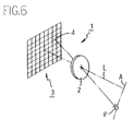
- the computer unit computes the position of the light point P based on the angle data transmitted from a plurality of CCD cameras 1.
- any conventional system determines three-dimensional dimension of a measurable object A by sequentially computing data collected from a number of light points P on the measurable object A.
- a laser scanner may be used for composing practical means for forming a number of light points P on a measurable object A by sequentially irradiating the object A with laser spot beam.
- a plurality of measuring-pont members 10 available for an optical measurement as the basis of the measurement are installed on the measurable object A or at plural positions in the periphery of the measurable object A.
- the computer unit computes absolute positions of respective CCD cameras 1 based on the positions of respective measuring-point members 10 seen from respective CCD cameras 1 and also based on the distance between the previously known two points on or in the periphery of the measurable object A.
- the conventional system uses those measuring-point members 10 which respectively use an LED light source and incorporate a cap lens 13 in the center of the front surface of a cylidrical system 11, where the cap lens 13 protects an LED light emitter 12 and evenly irradiates front domain of the light emitter 12 by emitting light beam.
- each of those conventional measuring-point members 10 for an optical measurement incorporates an LED light emitter 12 having a substantial area, and in addition, a cap lens 13 for protecting the LED light emitter 12 is installed around external periphery of the light emitter 12. Because of this structure, when each of those CCD cameras 1 picks up image of individual measuring-point members 10, the LED light emitter 12 itself is identified as a light ball having a substantial area, and yet, whenever varying angle to pick up image of respective measuring-point members 10, due to frictional effect of the cap lens 13 disposed in front of the LED light emitter 12, position of the most luminous domain inside of the light ball is variably seen.
- a position detecting apparatus is disclosed in GB-A-2005950 having a target defining four points (ABCD) in non-coplanar relationship, a first set of three points (ABC) lying in a first target plane and a second set of three points (BCD) lying in a second target plane.
- a two dimensional set of photosensitive elements at the focal plane of a camera receive radiation from the radiation emitters. The orientation of an object to which the target is attached may be determined in relation to a selected reference plane.
- DE-A-37 34821 discloses a schlieren optical device using monochromatic light emitting diodes.
- a first optical lens system receives light from the diode, a first condenser lens focuses the light from the diode to form an image thereof at the focal point of a first schlieren lens.
- a diffusing plate In the focusing plane lies, a diffusing plate to ensure uniformity of the light, and also a pin hole to cut out the excessive light.
- the invention provides a measuring-point member as claimed in claim 1 or 2.
- a fine through hole permitting permeation of light from a light source and a diffusible member for diffusing light are disposed in front of a light source.
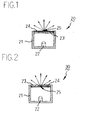
- Fig. 1 schematically illustrates a measuring-point member for an optical measurement according to the first embodiment of the invention.
- the reference numeral 21 shown in Fig. 1 designates a bottomed cylindrical casing having an aperture in the front.
- the reference numeral 22 designates a light-emitting diode (hereinafter merely called an LED) which itself makes up a light source being disposed at the center of the internal bottom of the casing 21.
- the reference numeral 23 designates a diffusible plate which diffuses light emitted from the LED 22 built in the aperture domain of the casing 21.
- the reference numeral 24 designates a light-shielding film adhered to the front surface of the diffusible plate 23.
- a pin hole 25 is provided through the center of the light-shielding film 24.
- a plurality of measuring-point members 20 respectively having the structure mentioned above are disposed in the periphery of or on a measurable object A.
- the built-in LED 22 emits light
- light emitted from the LED 22 is diffused by the diffusible plate 23, and then, the diffused light beam permeates the pin hole 25 formed through the light-shielding film 24 before irradiating front domain of respective measring-point members 20.
- each measuring-point member As viewed from each CCD camera 1 functioning as a two-dimensional photosensitive element, takes the form of a pin hole 25 formed in the light-shielding film 24, and therefore, each light emitter becomes an extremely fine spot light source. Light being emitted through the pin hole 25 is diffused by the diffusible plate 23, and in consequence, light containing weak directivity of light intensity is emitted through the pin hole 25.
- the optical measuring system can achieve extremely precise optical measuring effect.
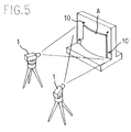
- Fig. 2 schematically illustrates a measuring-point member for optical measurement according to the second embodiment of the invention.
- the measuring-point member 30 shown in Fig. 2 comprises a bottomed cylindrical casing 21, an LED 22 housed in the casing 21, a diffusible plate 23 secured to the opening of the casing 21, and a light-shielding film 24 adhered to the diffusible plate 23 and having a pin hole 25 formed therethrough.
- the light-shielding film 24 having the pin hole 25 is attached to the front surface of the diffusible plate 23 in the second embodiment.
- the light-shielding film 24 is on the back surface of the diffusible plate 23.
- a plurality of measuring-point members 30 respectively having the structure mentioned above are disposed in the periphery of or on a measurable object A.
- the built-in LED 22 emits light
- light emitted from the LED 22 permeates the pin hole 25 formed through the light-shielding film 24, and then, while being diffused by the diffusible plate 23, the diffused light beam irradiates front domain of each measuring-point member 30.
- the light emitter of each measurable-point member 30 as viewed from each CCD camera 1 takes the form of a pin hole 25 formed in the light-shielding film 24, and therefore, the light emitter becomes an extremely fine spot light source. Then, light emitted through the pin hole 25 is diffused by the diffusible plate 23. In consequence, light emitted through the pin hole 25 irradiates front domain of respective measuring-point members 30 in the form of light containing weak directivity of light intensity.
- each CCD camera 1 picks up image of each measuring-point member 30
- the light emitter itself can be identified as an extremely fine spot light source. Furthermore, even when varying the angle for picking up image of each measuring-point member 30, apparent position of the light emitter remains invariable, and therefore, the optical measuring system can achieve extremely precise measuring effect.
- Fig. 3 schematically illustrates a measuring-point member according to the third embodiment of the invention.
- the measuring-point member 40 shown in Fig. 3 comprises a casing 41 which is composed of a bottomed cylindrical body 41, an LED 22 disposed in the center of the bottom of the casing 41, a light-shielding plate 42 secured to the opening of the casing 41 and having an extremely fine through-hole 43 formed in the center thereof, and a diffusible member 44 embedded in the through-hole 43 of the light-shielding plate 42.
- a plurality of measuring-point members 40 respectively having the structure mentioned above are disposed in the periphery of or on a measurable object A.
- the built-in LED 22 emits light
- light emitted from the LED 22 arrives at the through-hole 43 formed through the light-shielding plate 42, and then, while being diffused by the diffusible member 44 built in the through-hole 43, the diffused light irradiates front domain of each measuring-point member 40.
- the light emitter of the measuring-point member 40 as viewed from each CCD camera 1 takes the form of a fine through-hole 43 formed in the light-shielding plate 42, and therefore, the light emitter becomes an extremely fine spot light source. Furthermore, since light emitted through the fine through-hole 43 is diffused by the diffusible member 44 built in the fine through-hole 43, diffused light from the through-hole 43 irradiates front domain of each measuring-point member 40 in the form of light containing weak directivity of light intensity.
- the optical measuring system can achieve extremely precise optical measuring effect.
- each embodiment of the invention has solely referred to an example of disposing an LED 22 inside of casings 21 and 41.
- each embodiment of the invention it is also possible for each embodiment of the invention to provide a plurality of LEDs 22 inside of the casings 21 and 41 in the event that a short amount of light is emitted through the pin hole 25 or the through-hole 43.
- the invention provides a self-illuminating measuring-point member available for optical measurement, which is used for determining three-dimensional dimension of a measurable object upon activating a plurality of CCD cameras to pick up image of the measurable object.
- the measuring-point member according to the invention comprises an LED, a fine through-hole which permits light from the LED to pass therethrough, and a diffusible member which diffuses light permeating the fine through-hole.
- the optical measuring system utilizing the measuring-point member according to the invention condenses light from an LED through an extremely fine through-hole and diffuses light by means of a diffusible member.
- the optical measuring system of the invention can form an extremely fine spot light source capable of emitting light containing weak directivity of light intensity from an extremely fine light point available for optical measurement. Therefore, the optical measuring system can implement three-dimensional measurement with unsurpassed precision in the course of measuring three-dimensional dimension of a measurable object by means of a plurality of measuring-point members available for optical measurement.
Description
Claims (2)
- A measuring-point member (20;30) for executing an optical measurement using a plurality of self illuminating measuring-point members activating a plurality of two-dimensional photosensitive elements for determining the dimensions of a three-dimensional object, the measuring point member (20;30) comprises a casing (21) having an aperture, a light source (22) located in said casing, a diffusible plate (23) located in said aperture and disposed in front of said light source in order to diffuse light from said light source, and a light-shielding film (24) formed on the front or the back of the diffusible plate and having a through-hole (25) formed in a centre thereof; whereby, even when the angle of image pickup is varied, the apparent position of the measuring point member is constant.
- A measuring-point member (40) for executing an optical measurement using a plurality of self illuminating measuring-point members activating a plurality of two-dimensional photosensitive elements for determining the dimensions of a three-dimensional object, the measuring point member comprises a casing (41) having an aperture, a light source (42) located in said casing, a light-shielding plate (44) located in said aperture and disposed in front of said light source and having a through-hole (45) in a centre thereof, and a diffusible member which is built in said through-hole in order to diffuse light permeating said through-hole; whereby, even when the angle of image pickup is varied, the apparent position of the measuring point member is constant.
Applications Claiming Priority (2)
| Application Number | Priority Date | Filing Date | Title |
|---|---|---|---|
| JP00301793A JP3355583B2 (en) | 1993-01-12 | 1993-01-12 | Measurement point member for optical measurement |
| JP3017/93 | 1993-01-12 |
Publications (3)
| Publication Number | Publication Date |
|---|---|
| EP0606770A2 EP0606770A2 (en) | 1994-07-20 |
| EP0606770A3 EP0606770A3 (en) | 1995-09-20 |
| EP0606770B1 true EP0606770B1 (en) | 1998-08-12 |
Family
ID=11545572
Family Applications (1)
| Application Number | Title | Priority Date | Filing Date |
|---|---|---|---|
| EP93310586A Expired - Lifetime EP0606770B1 (en) | 1993-01-12 | 1993-12-29 | A measuring-point member for optical measurement |
Country Status (4)
| Country | Link |
|---|---|
| US (1) | US5424930A (en) |
| EP (1) | EP0606770B1 (en) |
| JP (1) | JP3355583B2 (en) |
| DE (1) | DE69320316T2 (en) |
Families Citing this family (5)
| Publication number | Priority date | Publication date | Assignee | Title |
|---|---|---|---|---|
| DE19536296B4 (en) * | 1995-09-29 | 2004-10-14 | Daimlerchrysler Ag | Signal marks and methods for their identification |
| DE19536295C2 (en) * | 1995-09-29 | 2000-12-14 | Daimler Chrysler Ag | Spatially designed signal mark |
| BE1016010A3 (en) * | 2004-05-10 | 2006-01-10 | Krypton Electronic Eng Nv | Measuring device and method for determining the position of a point on the verge of a plate-shaped object. |
| TWI354097B (en) * | 2007-12-31 | 2011-12-11 | Ind Tech Res Inst | Standard illuminant apparatus for providing standa |
| JP5915949B2 (en) | 2014-06-25 | 2016-05-11 | パナソニックIpマネジメント株式会社 | Projection system |
Family Cites Families (8)
| Publication number | Priority date | Publication date | Assignee | Title |
|---|---|---|---|---|
| US4114985A (en) * | 1974-03-28 | 1978-09-19 | Friedman Jerome D | Shield for high power infrared laser beam |
| GB2005950B (en) * | 1977-10-07 | 1982-02-10 | Secretary Industry Brit | Position detecting apparatus |
| US4466693A (en) * | 1980-11-25 | 1984-08-21 | Agency Of Industrial Science And Technology | Holographic straightness meter |
| JPH0827443B2 (en) * | 1986-10-16 | 1996-03-21 | オリンパス光学工業株式会社 | Shuriren optical device |
| JPS63235830A (en) * | 1987-03-24 | 1988-09-30 | Nikon Corp | Quantity-of-light detector |
| JP2642216B2 (en) * | 1989-05-23 | 1997-08-20 | サイベック システムズ | Semiconductor article pre-positioning method and apparatus |
| JPH0473702A (en) * | 1990-07-16 | 1992-03-09 | Mitsui Petrochem Ind Ltd | Diffuse reflector |
| JPH04139408A (en) * | 1990-10-01 | 1992-05-13 | Toshiba Corp | Fluorescent pinhole plate |
-
1993
- 1993-01-12 JP JP00301793A patent/JP3355583B2/en not_active Expired - Fee Related
- 1993-08-10 US US08/104,004 patent/US5424930A/en not_active Expired - Lifetime
- 1993-12-29 EP EP93310586A patent/EP0606770B1/en not_active Expired - Lifetime
- 1993-12-29 DE DE69320316T patent/DE69320316T2/en not_active Expired - Fee Related
Also Published As
| Publication number | Publication date |
|---|---|
| DE69320316D1 (en) | 1998-09-17 |
| JP3355583B2 (en) | 2002-12-09 |
| EP0606770A3 (en) | 1995-09-20 |
| EP0606770A2 (en) | 1994-07-20 |
| US5424930A (en) | 1995-06-13 |
| DE69320316T2 (en) | 1998-12-17 |
| JPH06207811A (en) | 1994-07-26 |
Similar Documents
| Publication | Publication Date | Title |
|---|---|---|
| CA2195359C (en) | Vision system and proximity detector | |
| US4867570A (en) | Three-dimensional information processing method and apparatus for obtaining three-dimensional information of object by projecting a plurality of pattern beams onto object | |
| US20050023448A1 (en) | Position-detecting device | |
| JP2002139304A (en) | Distance measuring device and distance measuring method | |
| US4534645A (en) | Automatic lens meter | |
| JP2002506976A (en) | Optical sensor system for detecting the position of an object | |
| US4501961A (en) | Vision illumination system for range finder | |
| JP2009236533A (en) | Calibration plate | |
| EP0606770B1 (en) | A measuring-point member for optical measurement | |
| US5572368A (en) | Light projecting device with cylindrical lens | |
| US4494868A (en) | Rangefinder device with focused elongated light source | |
| US5416317A (en) | Visual line detecting device | |
| US4907882A (en) | Surveying instrument for automatically taking measurements | |
| US5159378A (en) | Light projector for range finding device | |
| JPH10307025A (en) | Point light source device and photograph surveying target using point light source device | |
| JPH04110706A (en) | Device for taking three-dimensional form data | |
| JPH0473130B2 (en) | ||
| JPS5853449B2 (en) | Hanshiyagata Koden Switch | |
| JPS62291512A (en) | Distance measuring apparatus | |
| JP2589579Y2 (en) | Mounting structure of light emitting element for auto focus | |
| JP2983182B2 (en) | Emitter / receiver sensor | |
| JPH0789058B2 (en) | Distance measuring device | |
| JP2625722B2 (en) | Illumination device for focus detection | |
| RU2146039C1 (en) | Object position measurement technique | |
| JPH0753060Y2 (en) | Mounting device for light emitting element for distance measurement |
Legal Events
| Date | Code | Title | Description |
|---|---|---|---|
| PUAI | Public reference made under article 153(3) epc to a published international application that has entered the european phase |
Free format text: ORIGINAL CODE: 0009012 |
|
| AK | Designated contracting states |
Kind code of ref document: A2 Designated state(s): DE FR GB IT SE |
|
| PUAL | Search report despatched |
Free format text: ORIGINAL CODE: 0009013 |
|
| AK | Designated contracting states |
Kind code of ref document: A3 Designated state(s): DE FR GB IT SE |
|
| 17P | Request for examination filed |
Effective date: 19960315 |
|
| 17Q | First examination report despatched |
Effective date: 19960703 |
|
| GRAG | Despatch of communication of intention to grant |
Free format text: ORIGINAL CODE: EPIDOS AGRA |
|
| GRAG | Despatch of communication of intention to grant |
Free format text: ORIGINAL CODE: EPIDOS AGRA |
|
| GRAH | Despatch of communication of intention to grant a patent |
Free format text: ORIGINAL CODE: EPIDOS IGRA |
|
| GRAH | Despatch of communication of intention to grant a patent |
Free format text: ORIGINAL CODE: EPIDOS IGRA |
|
| ITF | It: translation for a ep patent filed |
Owner name: INTERPATENT ST.TECN. BREV. |
|
| GRAA | (expected) grant |
Free format text: ORIGINAL CODE: 0009210 |
|
| AK | Designated contracting states |
Kind code of ref document: B1 Designated state(s): DE FR GB IT SE |
|
| REF | Corresponds to: |
Ref document number: 69320316 Country of ref document: DE Date of ref document: 19980917 |
|
| ET | Fr: translation filed | ||
| PLBE | No opposition filed within time limit |
Free format text: ORIGINAL CODE: 0009261 |
|
| STAA | Information on the status of an ep patent application or granted ep patent |
Free format text: STATUS: NO OPPOSITION FILED WITHIN TIME LIMIT |
|
| 26N | No opposition filed | ||
| REG | Reference to a national code |
Ref country code: GB Ref legal event code: IF02 |
|
| PGFP | Annual fee paid to national office [announced via postgrant information from national office to epo] |
Ref country code: SE Payment date: 20021204 Year of fee payment: 10 |
|
| PGFP | Annual fee paid to national office [announced via postgrant information from national office to epo] |
Ref country code: FR Payment date: 20021210 Year of fee payment: 10 |
|
| PGFP | Annual fee paid to national office [announced via postgrant information from national office to epo] |
Ref country code: GB Payment date: 20021224 Year of fee payment: 10 |
|
| PGFP | Annual fee paid to national office [announced via postgrant information from national office to epo] |
Ref country code: DE Payment date: 20030109 Year of fee payment: 10 |
|
| PG25 | Lapsed in a contracting state [announced via postgrant information from national office to epo] |
Ref country code: GB Free format text: LAPSE BECAUSE OF NON-PAYMENT OF DUE FEES Effective date: 20031229 |
|
| PG25 | Lapsed in a contracting state [announced via postgrant information from national office to epo] |
Ref country code: SE Free format text: LAPSE BECAUSE OF NON-PAYMENT OF DUE FEES Effective date: 20031230 |
|
| PG25 | Lapsed in a contracting state [announced via postgrant information from national office to epo] |
Ref country code: DE Free format text: LAPSE BECAUSE OF NON-PAYMENT OF DUE FEES Effective date: 20040701 |
|
| EUG | Se: european patent has lapsed | ||
| GBPC | Gb: european patent ceased through non-payment of renewal fee |
Effective date: 20031229 |
|
| PG25 | Lapsed in a contracting state [announced via postgrant information from national office to epo] |
Ref country code: FR Free format text: LAPSE BECAUSE OF NON-PAYMENT OF DUE FEES Effective date: 20040831 |
|
| REG | Reference to a national code |
Ref country code: FR Ref legal event code: ST |
|
| PG25 | Lapsed in a contracting state [announced via postgrant information from national office to epo] |
Ref country code: IT Free format text: LAPSE BECAUSE OF NON-PAYMENT OF DUE FEES;WARNING: LAPSES OF ITALIAN PATENTS WITH EFFECTIVE DATE BEFORE 2007 MAY HAVE OCCURRED AT ANY TIME BEFORE 2007. THE CORRECT EFFECTIVE DATE MAY BE DIFFERENT FROM THE ONE RECORDED. Effective date: 20051229 |