EP0606548B1 - Apparatus for extracorporal therapy - Google Patents
Apparatus for extracorporal therapy Download PDFInfo
- Publication number
- EP0606548B1 EP0606548B1 EP93117784A EP93117784A EP0606548B1 EP 0606548 B1 EP0606548 B1 EP 0606548B1 EP 93117784 A EP93117784 A EP 93117784A EP 93117784 A EP93117784 A EP 93117784A EP 0606548 B1 EP0606548 B1 EP 0606548B1
- Authority
- EP
- European Patent Office
- Prior art keywords
- transducer
- ray
- tracking mark
- locating device
- focus
- Prior art date
- Legal status (The legal status is an assumption and is not a legal conclusion. Google has not performed a legal analysis and makes no representation as to the accuracy of the status listed.)
- Revoked
Links
Images


Classifications
-
- A—HUMAN NECESSITIES
- A61—MEDICAL OR VETERINARY SCIENCE; HYGIENE
- A61B—DIAGNOSIS; SURGERY; IDENTIFICATION
- A61B17/00—Surgical instruments, devices or methods, e.g. tourniquets
- A61B17/22—Implements for squeezing-off ulcers or the like on the inside of inner organs of the body; Implements for scraping-out cavities of body organs, e.g. bones; Calculus removers; Calculus smashing apparatus; Apparatus for removing obstructions in blood vessels, not otherwise provided for
- A61B17/225—Implements for squeezing-off ulcers or the like on the inside of inner organs of the body; Implements for scraping-out cavities of body organs, e.g. bones; Calculus removers; Calculus smashing apparatus; Apparatus for removing obstructions in blood vessels, not otherwise provided for for extracorporeal shock wave lithotripsy [ESWL], e.g. by using ultrasonic waves
- A61B17/2255—Means for positioning patient, shock wave apparatus or locating means, e.g. mechanical aspects, patient beds, support arms, aiming means
-
- A—HUMAN NECESSITIES
- A61—MEDICAL OR VETERINARY SCIENCE; HYGIENE
- A61B—DIAGNOSIS; SURGERY; IDENTIFICATION
- A61B17/00—Surgical instruments, devices or methods, e.g. tourniquets
- A61B17/22—Implements for squeezing-off ulcers or the like on the inside of inner organs of the body; Implements for scraping-out cavities of body organs, e.g. bones; Calculus removers; Calculus smashing apparatus; Apparatus for removing obstructions in blood vessels, not otherwise provided for
- A61B17/225—Implements for squeezing-off ulcers or the like on the inside of inner organs of the body; Implements for scraping-out cavities of body organs, e.g. bones; Calculus removers; Calculus smashing apparatus; Apparatus for removing obstructions in blood vessels, not otherwise provided for for extracorporeal shock wave lithotripsy [ESWL], e.g. by using ultrasonic waves
- A61B17/2256—Implements for squeezing-off ulcers or the like on the inside of inner organs of the body; Implements for scraping-out cavities of body organs, e.g. bones; Calculus removers; Calculus smashing apparatus; Apparatus for removing obstructions in blood vessels, not otherwise provided for for extracorporeal shock wave lithotripsy [ESWL], e.g. by using ultrasonic waves with means for locating or checking the concrement, e.g. X-ray apparatus, imaging means
- A61B17/2258—Implements for squeezing-off ulcers or the like on the inside of inner organs of the body; Implements for scraping-out cavities of body organs, e.g. bones; Calculus removers; Calculus smashing apparatus; Apparatus for removing obstructions in blood vessels, not otherwise provided for for extracorporeal shock wave lithotripsy [ESWL], e.g. by using ultrasonic waves with means for locating or checking the concrement, e.g. X-ray apparatus, imaging means integrated in a central portion of the shock wave apparatus
-
- A—HUMAN NECESSITIES
- A61—MEDICAL OR VETERINARY SCIENCE; HYGIENE
- A61B—DIAGNOSIS; SURGERY; IDENTIFICATION
- A61B6/00—Apparatus for radiation diagnosis, e.g. combined with radiation therapy equipment
- A61B6/12—Devices for detecting or locating foreign bodies
Definitions
- the invention relates to an extracorporeal therapy device with the features listed in the preamble of claim 1.
- Therapy devices of this type are used, for example, for crushing concrements or treating tissue (tumor treatment). They usually work with high-energy ultrasound, be it in the form of shock waves or in continuous or burst operation.
- a generic device is known from DE 39 16 093 A1.
- the lithotriptor described there has a dome-shaped transducer with an ultrasound locating device and an x-ray locating device integrated therein.
- the transducer and locating devices are firmly connected to one another and can be pivoted about a confocal axis with respect to the patient support. Since the focus remains unchanged when the transducer is pivoted with its locating devices, the direction of the sound waves can be changed without changing the position of the patient, which is of great advantage. For example, obstacles in the sound path can be avoided. This also offers particular advantages for location, since the focus area can be viewed from different directions and perspectives within the patient's body, whereby exact data about the spatial extent of any concretions or tissue areas to be treated can be obtained.
- the ultrasound locating device is often sufficient for numerous applications of the aforementioned lithotriptors.
- Therapy devices are therefore already known in which, in the case of a desired x-ray location, a separate x-ray location device must be placed on the therapy device.
- a commercially available X-ray C-arm can then be used here.
- the prerequisite is that the therapy device is designed so that there is still enough space for inserting this C-arm.
- the present invention is based on the object of designing a generic therapy device in such a way that on the one hand the X-ray locating device can be separated from the therapy device, but on the other hand this can be done quickly and easily while avoiding the aforementioned disadvantages connected to this and can be aligned to this.
- the x-ray location device is designed as a separate device, for example as an x-ray C-arm, and is detachably connected to the therapy device only via a coupling device.
- the invention provides a target mark that can be introduced into the focus of the converter for the X-ray location device on the therapy device. Since the transducer and the X-ray locating device are arranged so as to be pivotable about the same axis, the alignment with this target mark in the focus of the transducer is sufficient.
- the configuration according to the invention has the advantage that the advantages known in therapy devices with permanently assigned x-ray location devices, as are known, for example, from DE 39 16 093 A1, are essentially retained - in particular the pivoting movement of the transducer should be emphasized here - but the known disadvantages those with external x-ray location facilities known type go hand in hand, can be substantially avoided.
- the coupling required to connect the X-ray locating device to the therapy device can, as far as the X-ray locating device is concerned, be easily retrofitted so that the commercially available X-ray C-arms can be used. These are movable anyway and usually also adjustable in the height of their pivot axis, so that the pivot axis of the X-ray locating device and the transducer can be brought into agreement at least essentially by manual alignment.
- these additional devices consist on the one hand of the target mark for the x-ray locating device, which can be brought into the focus of the transducer, and on the other hand of a controller assigned to the x-ray locating device, which in conjunction with a position transmitter assigned to the transducer, the respective transducer position and thus also recognizes the swivel position of the x-ray locating device and thus assigns the focus position with respect to the x-ray locating device on the basis of a previously determined path curve.
- this path curve it is only necessary to determine the position of the focus with the aid of the target mark in two swivel positions, preferably the end positions, with the aid of the X-ray locating device, after which the control device determines this curve or the corresponding values determined and taken into account when displaying the electronic target mark on the monitor.
- the target for the X-ray locating device is expediently already provided on the therapy device, in particular the transducer, so that it only has to be brought into the focus position if necessary.
- a practical device for swiveling this target in and out on the ultrasound scanner is described below using an exemplary embodiment.
- the target mark can, however, also be attached to the dome membrane that closes the lead section on the device side towards the patient by gluing an appropriate X-ray positive mark there.
- an optical device is expediently provided which, for example, consists of two lasers arranged within the converter, the beams of which intersect in the focus of the converter.
- the commercial X-ray C-arms already mentioned have an X-ray source at one end of the C and an X-ray image intensifier at the other end, the signal of which is fed to an image display device, usually a monitor.
- a target mark that corresponds to the central beam of the x-ray source can usually be displayed on this monitor.
- this central beam and thus the target mark defined in the monitor must be brought into agreement with the converter focus.
- Such positioning with millimeter precision is very time-consuming.
- the solution according to the invention only provides a rough manual alignment and, in an advantageous development, has the possibility of tracking the electronic target to the target actually depicted. This makes it possible to display the focus of the transducer on the monitor without an exact alignment of the x-ray locating device, even if the actual target is not in the area of the central beam.
- a control device which tracks the electronic target mark according to the respective swivel position of the transducer, specifically on a basis based on the actual focus position in FIG the path determined by the swivel end positions.
- Displacement sensor in The sense of the invention is a sensor that detects the position of the transducer, be it by distance measurement, by angle measurement or in some other way.
- the coupling device which fixes the x-ray locating device on the therapy device, is arranged on the therapy device side near the transducer and on the x-ray locating device side on the support frame, specifically in the vicinity of the x-ray source.
- This achieves a connection via short levers and also ensures a very precise arrangement between the X-ray source and transducer.
- a window for the x-ray source is provided within the transducer dome.
- the invention also provides a method for setting up an external x-ray locating device on such a therapy device that can be carried out simply and quickly, with which an association between transducer focus and x-ray locating device takes place in accordance with the respective pivot position.
- the transducer After coupling the X-ray locating device to the transducer of the therapy device, that is to say after the mechanical connection of the units, the transducer is pivoted into an end position together with the X-ray locating device.
- the target for the X-ray location i.e. an X-ray positive mark, is placed in the focus of the transducer (this can of course also be done in any time beforehand).
- the target mark is imaged on the image display device by means of the X-ray locating device and the position of this target mark is stored in a control device.
- the transducer is then pivoted into its other end position together with the X-ray locating device and the position of the target mark depicted is again stored.
- setup is complete.
- the control device now calculates a path that indicates the position of the transducer focus as a function of the pivot position of the transducer.
- the electronic target mark provided in the image display device is tracked on the basis of these path parameters, so that the electronic target mark of the X-ray locating device always corresponds with high accuracy to the actual focus position of the converter.
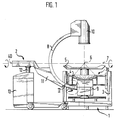
- the arrangement according to FIG. 1 shows an extracorporeal therapy device 1 with a coupled x-ray locating device 2.
- the therapy device 1 essentially consists of a support frame 3 in which an electroacoustic transducer 4 is pivotally mounted and on which a patient support 5 is adjustably attached.
- the usually required auxiliary units, such as control electronics, actuators, etc. are not shown.
- the transducer 4 consists of a large number of dome-shaped piezoelectric elements, its focus is denoted by 6.
- the converter 4 is pivotally mounted on the swivel table 3a within the support frame 3 about the axis 7 in which the focus 6 lies. It can be swiveled out of the position shown perpendicular to the patient support 5 by 15 ° on both sides. In order to position a patient on the patient support 5, the patient support 5 be positioned in all three spatial coordinates to the support frame 3 and the transducer 4.
- the X-ray locating device 2 is designed as a commercially available X-ray C-arm.
- the actual C-arm 8 is part of the supporting frame.
- An X-ray source 9 is arranged at one end of this arch 8, and an X-ray image intensifier 10 is arranged on the opposite side.
- the C-arm 8 is designed as a profile and is guided in the direction of its arch on an arm 11 which in turn is connected via an arm (not shown in detail).
- Lifting device 12 is connected to the chassis 13.
- the arm 11 is mounted on the lifting device 12 so that the entire C-arm can be pivoted with the arm 11 about the axis 40, which does not necessarily have to coincide exactly with the axis 7.
- the C-arm 8 is first of all aligned by means of the lifting device 12 such that the axis 40 is approximately aligned with the axis 7.
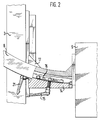
- the lower end of the C-arm, which carries the X-ray source 9, is then inserted into the support frame 3 of the therapy device 1 until the X-ray source 9 is in register with the X-ray window (not shown) provided in the transducer 4. In this position, the coupling shown in detail in FIGS. 2 to 4 is to be connected, which creates a firm mechanical connection between the devices.
- the coupling consists of a part on the C-arm side and a part on the device side.
- a coupling body 14 is fixed near the X-ray source 9 by means of the guide groove of the C-arm which is present in the C-arm 8 and is open to the outside.
- This coupling body 14 can be fixed via a lever 15 with respect to a clamping plate 16 running within the groove.
- the Coupling body 14 is essentially cuboid, but is adapted to it in the region of the C-arm 8, so that a large-area, secure contact is ensured.
- At the side of the coupling body 14 there is an angle plate 17 which is screwed to the coupling body 14.
- This angle plate 17 comes to rest on a flat side of the swivel table 3a, specifically on a clamping plate 18.
- This clamping plate 18 forms the part of the coupling on the device side. It has a groove 19 with a T-shaped cross section, into which a clamping bolt 20 which passes through the corresponding leg of the angle plate 17 engages and which can be tensioned by means of a lever 21 which engages on the outside of the angle plate and with which the angle plate 17 is firmly connected to the clamping plate 18 can be.
- the actual coupling process takes place between the X-ray locating device 2 and the swiveling table 3a in the therapy device 1. Because of the large contact surfaces of the coupling, the forces occurring here can be safely transmitted, in particular it is ensured that the C-arm 8 follows the pivoting movements of the transducer 4.
- this mechanical coupling between the X-ray locating device 2 and the therapy device 1 only provides a rough alignment; the exact setting is carried out by electronically tracking the target mark on the monitor of the X-ray locating device.
- the arrangement of an x-ray positive target 22 in focus 6 is required, which can then be displayed by means of the x-ray location device 2.
- These Target 22, for example in the form of a lead ball, as shown in Figures 5 to 9, can be attached in various ways.
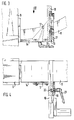
- FIGS. 5 to 7 An embodiment is described with reference to FIGS. 5 to 7, in which this target mark is arranged so that it can be swung out at the end of an ultrasound scanner 23 on the patient side.
- the target 22 is held by an arm 24 which is pivotally mounted at its end on the scanner side with an axis 25 extending transversely to the longitudinal axis of the scanner such that the target, as shown, can be pivoted into the focus or can be applied to the scanner 23.
- the pivoting takes place via a rotation of the scanner 23 within a stationary tube 26 surrounding it.
- a spur gear 27 which is fixedly connected to the axle 25 and meshes with a corresponding toothing 28 provided on the free end face of the tube 26.
- the toothing 28 extends, as can be seen in FIG.
- the ultrasound scanner 23 In order to be able to scan in different planes during the ultrasound location, it is customary to arrange the ultrasound scanner 23 rotatably. So that the target mark 22 is not inadvertently swung out during these normal rotary movements during locating, part of the end face of the tube 26 is not toothed, so that the target mark 22 is pivoted in only when the scanner 23 is rotated beyond 180 ° on both sides .
- FIG. 1 An alternative device for attaching the target 22 is shown in FIG.
- a telescopic device 29 is provided with which the target 22 can be positioned in the focus of the transducer via the extendable telescope 29.
- the telescope 29 can be actuated mechanically, pneumatically or hydraulically.
- the target mark 22 can be positioned on a rod 32 in the focus 6 of the transducer via a guide tube 31 arranged on the side of the transducer.
- the guide tube 31 is tightly integrated into the lead section, the rod 32 is displaceable and mounted tightly within the guide tube 31.
- a stop is also provided here in order to reach the focus position quickly and safely.
- the focus position of the target 22 can also be checked via the ultrasound scanner 23.
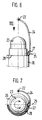
- FIGS. 10 and 11 An alternative device for attaching an x-ray positive target 22 is shown with reference to FIGS. 10 and 11.
- two HE-NE lasers 41 are arranged approximately diametrically opposite one another, the light beams 42 of which intersect in the focus 6 of the converter 4.
- the coupling membrane 30 is first adjusted in its distance from the transducer 4 until the light spots 43 generated on the membrane 30 by the light beams 42 are brought into line, as shown in FIG.
- an x-ray positive target mark 22 for example in the form of a metal cross, is glued to the membrane in place of the light spots 43. This ensures the exact positioning of the target 22 in the focus 6 of the converter 4.
- the electronic correction described above which ensures that the one shown on the monitor 33 is illustrated with reference to FIG Target always corresponds to focus 6 of the converter.
- the video output signal of the X-ray image intensifier 10 is denoted by 34 in FIG.
- This signal then passes through a target mark generator 35, which generates an electronic target mark at the location of the monitor image.
- a control device 36 Downstream of the target mark generator 35 is a control device 36, which receives a signal about the swivel position of the converter via a transducer 37 arranged on the transducer and has data access via a memory 38 to the actual coordinates of the shown target mark 22 in the end positions of the transducer 4.
- the control device 36 uses the coordinates stored in the memory 38 to calculate a path K on which the focus 6 travels about the axis 7 when the transducer 4 is pivoted or about the axis 40 when the X-ray C-arm 8 is also pivoted. The resulting deviations are determined, the electronic target mark E generated by generator 35 is tracked and displayed in monitor 33 at the calculated location corresponding to focus 6.
- the values defined in the memory 38 are determined during setup, as described at the beginning.
- the setup process is explained below with reference to FIG. 13: With reference to FIGS. 13A and 13B, the principle of tracking the electronic mark to the illustrated target mark is first explained.
- the target mark 22 shown is marked with M, the electronic mark with E.
- the coordinates X and Y must be entered. Such an input can be made using buttons or with the help of an optical pointing device.
- the coordinates X and Y in the two extreme positions of the transducer are stored in the memory 38.
- a path K is calculated within the control device 36, which represents the position of the focus as a function of the swivel movement with respect to the X-ray locating device .
- the target mark E is displayed on the monitor 33 in accordance with the respective swivel position during the later location.
Description
Die Erfindung betrifft ein extrakorporales Therapiegerät mit den im Oberbegriff des Anspruchs 1 aufgeführten Merkmalen.The invention relates to an extracorporeal therapy device with the features listed in the preamble of
Derartige Therapiegeräte werden beispielsweise bei der Zertrümmerung von Konkrementen oder der Behandlung von Gewebe (Tumorbehandlung) eingesetzt. Sie arbeiten in der Regel mit Hochenergie-Ultraschall, sei es in Form von Stoßwellen oder im Dauer- oder Burstbetrieb.Therapy devices of this type are used, for example, for crushing concrements or treating tissue (tumor treatment). They usually work with high-energy ultrasound, be it in the form of shock waves or in continuous or burst operation.
Ein gattungsgemäßes Gerät ist aus DE 39 16 093 A1 bekannt. Der dort beschriebene Lithotriptor weist einen kalottenförmigen Wandler mit darin integrierter Ultraschallortungseinrichtung und Röntgenortungseinrichtung auf. Wandler und Ortungseinrichtungen sind fest miteinander verbunden und können in bezug auf die Patientenauflage um eine konfokale Achse geschwenkt werden. Da beim Schwenken des Wandlers mit seinen Ortungseinrichtungen der Fokus unverändert bleibt, können ohne Lageveränderung des Patienten die Richtung der Schallwellen geändert werden, was von großem Vorteil ist. So können beispielsweise Hindernisse im Schallweg umgangen werden. Auch für die Ortung bietet dies besondere Vorteile, da der Fokusbereich innerhalb des Patientenkörpers aus unterschiedlichen Richtungen und Blickwinkeln betrachtet werden kann, wodurch exakte Daten über die räumliche Erstreckung etwaiger Konkremente oder zu behandelnder Gewebebereiche erhalten werden können.A generic device is known from DE 39 16 093 A1. The lithotriptor described there has a dome-shaped transducer with an ultrasound locating device and an x-ray locating device integrated therein. The transducer and locating devices are firmly connected to one another and can be pivoted about a confocal axis with respect to the patient support. Since the focus remains unchanged when the transducer is pivoted with its locating devices, the direction of the sound waves can be changed without changing the position of the patient, which is of great advantage. For example, obstacles in the sound path can be avoided. This also offers particular advantages for location, since the focus area can be viewed from different directions and perspectives within the patient's body, whereby exact data about the spatial extent of any concretions or tissue areas to be treated can be obtained.
Als nachteilig bei derartigen mit Röntgen- und Ultraschallortung ausgestatteten Therapiegeräten wird der vergleichsweise hohe Anschaffungspreis empfunden. Bei der immer vielseitiger werdenden Anwendung sowohl der Therapiegeräte als auch der Ortungseinrichtungen gibt es Bestrebungen, diese zumindest zeitweise voneinander zu trennen, um sie unabhängig voneinander nutzen zu können und somit die Wirtschaftlichkeit zu erhöhen.The comparatively high purchase price is perceived as disadvantageous in such therapy devices equipped with X-ray and ultrasound location. With the ever more versatile use of both the therapy devices and the locating devices, efforts are being made to separate them from one another at least temporarily in order to be able to use them independently of one another and thus to increase efficiency.
So reicht bei zahlreichen Anwendungen der vorerwähnten Lithotriptoren häufig die Ultraschallortungseinrichtung aus. Es sind daher schon Therapiegeräte bekannt, bei denen für den Fall einer gewünschten Röntgenortung eine gesonderte Röntgenortungseinrichtung an das Therapiegerät herangestellt werden muß. Hier kann dann ein handelsüblicher Röntgen-C-Bogen Verwendung finden. Voraussetzung ist jedoch, daß das Therapiegerät so ausgebildet ist, daß noch genügend Raum zum Einschieben dieses C-Bogens verbleibt.Thus, the ultrasound locating device is often sufficient for numerous applications of the aforementioned lithotriptors. Therapy devices are therefore already known in which, in the case of a desired x-ray location, a separate x-ray location device must be placed on the therapy device. A commercially available X-ray C-arm can then be used here. However, the prerequisite is that the therapy device is designed so that there is still enough space for inserting this C-arm.
Eine solche Anwendung von extrakorporalem Therapiegerät in Verbindung mit einer externen Röntgenortungseinrichtung ist beispielhaft in EP 0 402 584 A1 beschrieben. Dort geht es im wesentlichen um das sich regelmäßig bei solchen Anordnungen stellende Problem der räumlichen Zuordnung zwischen Röntgenortungseinrichtung und dem Fokus des elektroakustischen Wandlers. Dieses Problem wird durch eine Art Zieleinrichtung gelöst, die am Wandler angebracht wird und anhand der der Röntgenbogen in zwei Stellungen auf den Fokus ausgerichtet wird. Die hierzu erforderlichen Justierarbeiten sind nicht nur zeitaufwendig, sondern belasten den Patienten auch wegen der dabei auftretenden Röntgenstrahlung. Ein weiterer Nachteil ist darin zu sehen, daß immer dann, wenn die Stellung des Wandlers in bezug auf den Patienten geändert wird, wenn beispielsweise bestimmte Körperbereiche abgeschattet und daher von einer Seite nicht zugänglich sind, stets die Röntgenortungseinrichtung neu ausgerichtet werden muß.Such an application of extracorporeal therapy device in connection with an external x-ray location device is described by way of example in EP 0 402 584 A1. It is essentially about the problem of the spatial assignment between the X-ray locating device and the focus of the electroacoustic transducer that regularly arises in such arrangements. This problem is solved by a kind of aiming device, which is attached to the transducer and by means of which the X-ray arch is aligned with the focus in two positions. The adjustment work required for this is not only time-consuming, but also burden the patient because of the resulting X-rays. Another disadvantage is the fact that whenever the position of the transducer with respect to the patient is changed, for example if certain areas of the body are shadowed and are therefore not accessible from one side, the X-ray locating device must always be realigned.
Aus der nachveröffentlichten EP 0 538 659 A2 ist es bereits bekannt, eine Röntgenortungseinrichtung in Form eines externen Röntgen-C-Bogens im Bedarfsfalle an ein extrakorporales Therapiegerät derart anzukoppeln, daß es zusammen mit dem Therapiegerät um den Fokus des Wandlers schwenkbar ist. Auch dort ist bereits eine Zieleinrichtung vorgesehen, mit der die Röntgenortungseinrichtung in bezug auf den Wandlerfokus ausrichtbar ist. Die dort beschriebene Zieleinrichtung ist im Strahlengang zwischen Röntgenquelle und Röntgenbildempfangsvorrichtung in Form von zwei in Überdeckung zu bringende Zielmarken vorgesehen bzw. in diesen Strahlengang einschwenkbar, und zwar außerhalb des Fokus des Wandlers.From post-published EP 0 538 659 A2 it is already known to couple an X-ray locating device in the form of an external X-ray C-arm to an extracorporeal therapy device in such a way that it can be pivoted together with the therapy device about the focus of the transducer. A target device is already provided there, with which the x-ray locating device can be aligned with respect to the converter focus. The aiming device described there is provided in the beam path between the X-ray source and the X-ray image receiving device in the form of two target marks to be overlapped or can be pivoted into this beam path, specifically outside the focus of the transducer.
Ausgehend von dem einleitend genannten Stand der Technik nach DE 39 16 093 A1 liegt der vorliegenden Erfindung die Aufgabe zugrunde, ein gattungsgemäßes Therapiegerät so auszubilden, daß einerseits die Röntgenortungseinrichtung vom Therapiegerät getrennt werden kann, andererseits diese aber schnell und einfach unter Vermeidung der vorgenannten Nachteile mit diesem verbunden und auf dieses ausgerichtet werden kann.Based on the prior art mentioned in the introduction according to DE 39 16 093 A1, the present invention is based on the object of designing a generic therapy device in such a way that on the one hand the X-ray locating device can be separated from the therapy device, but on the other hand this can be done quickly and easily while avoiding the aforementioned disadvantages connected to this and can be aligned to this.
Erfindungsgemäß wird dies dadurch erreicht, daß die Röntgenortungseinrichtung als gesondertes Gerät, beispielsweise als Röntgen-C-Bogen ausgebildet und lediglich über eine Kupplungseinrichtung lösbar mit dem Therapiegerät verbunden wird. Um eine schnelle und genaue Ausrichtung der Röntgenortungseinrichtung in bezug auf das Therapiegerät, insbesondere den Wandlerfokus zu gewährleisten, sieht die Erfindung eine in den Fokus des Wandlers einbringbare Zielmarke für die Röntgenortungseinrichtung am Therapiegerät vor. Da Wandler und Röntgenortungseinrichtung um dieselbe Achse schwenkbar angeordnet sind, genügt die Ausrichtung auf diese Zielmarke im Fokus des Wandlers.According to the invention, this is achieved in that the x-ray location device is designed as a separate device, for example as an x-ray C-arm, and is detachably connected to the therapy device only via a coupling device. In order to quickly and accurately align the X-ray locating device with respect to the Therapy device, in particular to ensure the converter focus, the invention provides a target mark that can be introduced into the focus of the converter for the X-ray location device on the therapy device. Since the transducer and the X-ray locating device are arranged so as to be pivotable about the same axis, the alignment with this target mark in the focus of the transducer is sufficient.
Die erfindungsgemäße Ausbildung hat den Vorteil, daß die bei Therapiegeräten mit fest zugeordneten Röntgenortungseinrichtungen, wie sie beispielsweise aus DE 39 16 093 A1 bekannt sind, bekannten Vorteile im wesentlichen erhalten bleiben - hier ist insbesondere die Schwenkbewegbarkeit des Wandlers hervorzuheben -, jedoch die bekannten Nachteile, die mit externen Röntgenortungseinrichtungen bekannter Art einhergehen, im wesentlichen vermieden werden können. Die zum Anschluß der Röntgenortungseinrichtung an das Therapiegerät erforderliche Kupplung kann, soweit es die Röntgenortungseinrichtung betrifft, ohne weiteres nachgerüstet werden, so daß die handelsüblichen Röntgen-C-Bögen Verwendung finden können. Diese sind ohnehin verfahrbar und meist auch in der Höhe ihrer Schwenkachse einstellbar, so daß die Schwenkachse der Röntgenortungseinrichtung und des Wandlers zumindest im wesentlichen durch manuelles Ausrichten in Übereinstimmung gebracht werden können.The configuration according to the invention has the advantage that the advantages known in therapy devices with permanently assigned x-ray location devices, as are known, for example, from DE 39 16 093 A1, are essentially retained - in particular the pivoting movement of the transducer should be emphasized here - but the known disadvantages those with external x-ray location facilities known type go hand in hand, can be substantially avoided. The coupling required to connect the X-ray locating device to the therapy device can, as far as the X-ray locating device is concerned, be easily retrofitted so that the commercially available X-ray C-arms can be used. These are movable anyway and usually also adjustable in the height of their pivot axis, so that the pivot axis of the X-ray locating device and the transducer can be brought into agreement at least essentially by manual alignment.
Es stellt jedoch kein Problem dar, wenn diese Achsen nicht miteinander fluchten sondern geringfügig auseinanderfallen. Gemäß der Erfindung sind Zusatzeinrichtungen vorgesehen, mit denen in einfacher und sehr praktikabler Weise eine exakte Zuordnung der Röntgenortungseinrichtung zum Fokus des Wandlers gewährleistet ist, und das über den gesamten Schwenkbereich des Wandlers. Nach dem Einrichten und Ankuppeln der Röntgenortungseinrichtung bleibt diese Zuordnung so lange erhalten, bis die Geräte wieder voneinander getrennt werden.However, it is not a problem if these axes do not align with each other but fall apart slightly. According to the invention, additional devices are provided with which an exact assignment of the X-ray locating device to the focus of the transducer is ensured in a simple and very practical manner, and this over the entire pivoting range of the transducer. After setting up and coupling the X-ray locating device, this assignment is retained until the devices are separated from each other again.
In einer Weiterbildung der Erfindung bestehen diese Zusatzeinrichtungen zum einen aus der Zielmarke für die Röntgenortungseinrichtung, die in den Fokus des Wandlers einbringbar ist, und zum anderen aus einer der Röntgenortungseinrichtung zugeordneten Steuerung, die in Verbindung mit einem dem Wandler zugeordneten Positionsgeber die jeweilige Wandlerstellung und damit auch Schwenkstellung der Röntgenortungseinrichtung erkennt und damit die Fokuslage in bezug auf die Röntgenortungseinrichtung anhand einer vorher ermittelten Wegkurve zuordnet. Zur Ermittlung dieser Wegkurve ist es lediglich erforderlich, die Lage des Fokus mit Hilfe der Zielmarke in zwei Schwenkstellungen, vorzugsweise den Endpositionen, mit Hilfe der Röntgenortungseinrichtung zu ermitteln, wonach die Steuereinrichtung diese Kurve bzw. die entsprechenden Werte ermittelt und bei der Darstellung der elektronischen Zielmarke auf den Monitor berücksichtigt.In a further development of the invention, these additional devices consist on the one hand of the target mark for the x-ray locating device, which can be brought into the focus of the transducer, and on the other hand of a controller assigned to the x-ray locating device, which in conjunction with a position transmitter assigned to the transducer, the respective transducer position and thus also recognizes the swivel position of the x-ray locating device and thus assigns the focus position with respect to the x-ray locating device on the basis of a previously determined path curve. To determine this path curve, it is only necessary to determine the position of the focus with the aid of the target mark in two swivel positions, preferably the end positions, with the aid of the X-ray locating device, after which the control device determines this curve or the corresponding values determined and taken into account when displaying the electronic target mark on the monitor.
Zweckmäßigerweise ist die Zielmarke für die Röntgenortungseinrichtung bereits am Therapiegerät, insbesondere dem Wandler vorgesehen, so daß diese bei Bedarf nur noch in die Fokuslage gebracht werden muß. Dies kann zweckmäßigerweise dadurch erfolgen, daß innerhalb des Wandlers oder nahe am Wandler eine ein- und ausfahrbare Teleskopeinrichtung vorgesehen ist, an deren Ende diese Zielmarke sitzt, so daß bei ausgefahrenem Teleskop die Zielmarke im Fokus des Wandlers liegt und bei eingefahrenem Teleskop weder Therapie noch Ortung behindert.The target for the X-ray locating device is expediently already provided on the therapy device, in particular the transducer, so that it only has to be brought into the focus position if necessary. This can expediently take place in that a retractable and extendable telescope device is provided within the transducer or close to the transducer, at the end of which this target is located, so that the target is in the focus of the transducer when the telescope is extended and neither therapy nor location when the telescope is retracted with special needs.
Vorteilhaft kann dies auch durch eine Anbringung der Zielmarke am patientenseitigen Ende des Ultraschallscanners vorgesehen sein. Eine zweckmäßige Vorrichtung zum Aus- und Einschwenken dieser Zielmarke am Ultraschallscanner ist weiter unten anhand eines Ausführungsbeispiels beschrieben.This can advantageously also be provided by attaching the target to the patient-side end of the ultrasound scanner. A practical device for swiveling this target in and out on the ultrasound scanner is described below using an exemplary embodiment.
Die Zielmarke kann jedoch auch auf der die geräteseitige Vorlaufstrecke zum Patienten hin abschließenden Kuppelmembran angebracht werden, indem dort eine entsprechende röntgenpositive Marke aufgeklebt wird. Um auch sicherzustellen, daß diese Marke tatsächlich im Fokus des Wandlers angeordnet ist, wird zweckmäßigerweise eine optische Einrichtung vorgesehen, die beispielsweise aus zwei innerhalb des Wandlers angeordneten Lasern besteht, deren Strahlen sich im Fokus des Wandlers schneiden. Wenn die beiden sich auf der Membran bildenden Leuchtflecke durch Verschiebung der Membran in Überdeckung gebracht sind, befindet sich die entsprechende Stelle der Membran im Fokus des Wandlers. Es kann dann an dieser Stelle eine röntgenpositive Zielmarke aufgeklebt werden.The target mark can, however, also be attached to the dome membrane that closes the lead section on the device side towards the patient by gluing an appropriate X-ray positive mark there. In order to also ensure that this mark is actually arranged in the focus of the converter, an optical device is expediently provided which, for example, consists of two lasers arranged within the converter, the beams of which intersect in the focus of the converter. When the two light spots forming on the membrane are overlapped by shifting the membrane, the corresponding location of the membrane is in the focus of the transducer. An X-ray positive target can then be stuck on at this point.
Die bereits angesprochenen handelsüblichen Röntgen-C-Bögen weisen an einem Ende des C eine Röntgenquelle und am anderen Ende einen Röntgenbildverstärker auf, dessen Signal einer Bildwiedergabeeinrichtung, in der Regel einem Monitor, zugeführt wird. Auf diesem Monitor ist üblicherweise eine Zielmarke darstellbar, die mit dem Zentralstrahl der Röntgenquelle übereinstimmt. Bei Anordnungen nach dem Stand der Technik ist es stets so, daß dieser Zentralstrahl und damit die im Monitor festgelegte Zielmarke mit dem Wandlerfokus in Übereinstimmung gebracht werden muß. Eine solche milimetergenaue Positionierung ist sehr zeitaufwendig. Die erfindungsgemäße Lösung sieht hingegen nur eine manuelle Grobausrichtung vor und weist in einer vorteilhaften Weiterbildung die Möglichkeit auf, die elektronische Zielmarke auf die tatsächlich abgebildete Zielmarke nachzuführen. Hiermit ist es also ohne exakte Ausrichtung der Röntgenortungseinrichtung möglich, den Fokus des Wandlers auf dem Monitor darzustellen, auch wenn die tatsächliche Zielmarke sich nicht im Bereich des Zentralstrahls befindet.The commercial X-ray C-arms already mentioned have an X-ray source at one end of the C and an X-ray image intensifier at the other end, the signal of which is fed to an image display device, usually a monitor. A target mark that corresponds to the central beam of the x-ray source can usually be displayed on this monitor. In the case of arrangements according to the prior art, it is always the case that this central beam and thus the target mark defined in the monitor must be brought into agreement with the converter focus. Such positioning with millimeter precision is very time-consuming. The solution according to the invention, on the other hand, only provides a rough manual alignment and, in an advantageous development, has the possibility of tracking the electronic target to the target actually depicted. This makes it possible to display the focus of the transducer on the monitor without an exact alignment of the x-ray locating device, even if the actual target is not in the area of the central beam.
Um dies auch mit der erforderlichen Genauigkeit in jeder Schwenkstellung des Wandlers und der Röntgenortungseinrichtung zu gewährleisten, ist gemäß der Weiterbildung der Erfindung eine Steuereinrichtung vorgesehen, welche die elektronische Zielmarke entsprechend der jeweiligen Schwenkstellung des Wandlers nachführt, und zwar auf einer vorher anhand der tatsächlichen Fokuslage in den Schwenkendstellungen ermittelten Bahn.In order to ensure this with the required accuracy in each swivel position of the transducer and the X-ray locating device, a control device is provided according to the development of the invention, which tracks the electronic target mark according to the respective swivel position of the transducer, specifically on a basis based on the actual focus position in FIG the path determined by the swivel end positions.
Um an der Röntgenortungseinrichtung möglichst wenig bauliche Änderungen vornehmen zu müssen, ist es zweckmäßig, nicht die Schwenkstellung der Röntgenortungseinrichtung, sondern die des Wandlers innerhalb des Therapiegerätes zu erfassen und der Steuereinrichtung zuzuführen. Eine solche Erfassung kann durch einen am Wandler vorgesehenen Wegaufnehmer erfolgen. Wegaufnehmer im Sinne der Erfindung ist ein Sensor, der die Stellung des Wandlers erfaßt, sei es durch Wegmessung, durch Winkelmessung oder auf andere Weise.In order to make the least possible structural changes to the x-ray locating device, it is expedient not to detect the pivoting position of the x-ray locating device but rather that of the transducer within the therapy device and to feed it to the control device. Such detection can be carried out by a transducer provided on the transducer. Displacement sensor in The sense of the invention is a sensor that detects the position of the transducer, be it by distance measurement, by angle measurement or in some other way.
Von Vorteil ist es, wenn die Kupplungseinrichtung, die die Röntgenortungseinrichtung am Therapiegerät festlegt therapiegeräteseitig nahe dem Wandler und auf Seiten der Röntgenortungseinrichtung am Traggestell, und zwar in der Nähe der Röntgenquelle angeordnet ist. Hierdurch wird eine Verbindung über kurze Hebel erreicht und zudem eine recht genaue Anordnung zwischen Röntgenquelle und Wandler gewährleistet. Insbesondere bei einem kalottenförmig ausgebildeten und aus piezoelektrischen Elementen aufgebauten Wandler ist es zweckmäßig, wenn innerhalb der Wandlerkalotte ein Fenster für die Röntgenquelle vorgesehen ist.It is advantageous if the coupling device, which fixes the x-ray locating device on the therapy device, is arranged on the therapy device side near the transducer and on the x-ray locating device side on the support frame, specifically in the vicinity of the x-ray source. This achieves a connection via short levers and also ensures a very precise arrangement between the X-ray source and transducer. Particularly in the case of a dome-shaped transducer and constructed from piezoelectric elements, it is expedient if a window for the x-ray source is provided within the transducer dome.
Neben der vorrichtungsmäßigen Ausbildung gibt die Erfindung auch ein einfach und schnell durchzuführendes Verfahren zum Einrichten einer externen Röntgenortungseinrichtung an einem solchen Therapiegerät an, mit dem eine Zuordnung zwischen Wandlerfokus und Röntgenortungseinrichtung entsprechend der jeweiligen Schwenkstellung erfolgt. Nach dem Ankuppeln der Röntgenortungseinrichtung an den Wandler des Therapiegerätes, also nach der mechanischen Verbindung der Aggregate, wird der Wandler zusammen mit der Röntgenortungseinrichtung in eine Endstellung geschwenkt. Dann wird die Zielmarke für die Röntgenortung, also eine röntgenpositive Marke, im Fokus des Wandlers angebracht (dies kann natürlich auch in beliebiger Zeit vorher erfolgen). Mittels der Röntgenortungseinrichtung wird die Zielmarke auf der Bildwiedergabeeinrichtung abgebildet und die Lage dieser Zielmarke in einer Steuereinrichtung gespeichert. Sodann wird der Wandler zusammen mit der Röntgenortungseinrichtung in seine andere Endstellung geschwenkt und wiederum die Lage der abgebildeten Zielmarke gespeichert. Nachdem die Zielmarke aus dem Fokus entfernt worden ist, ist das Einrichten beendet. Die Steuereinrichtung errechnet nun eine Bahn, welche die Lage des Wandlerfokus in Abhängigkeit der Schwenkstellung des Wandlers angibt. Die in der Bildwiedergabeeinrichtung vorgesehene elektronische Zielmarke wird anhand dieser Bahnparameter nachgeführt, so daß die elektronische Zielmarke der Röntgenortungseinrichtung stets mit hoher Genauigkeit der tatsächlichen Fokuslage des Wandlers entspricht.In addition to the design of the device, the invention also provides a method for setting up an external x-ray locating device on such a therapy device that can be carried out simply and quickly, with which an association between transducer focus and x-ray locating device takes place in accordance with the respective pivot position. After coupling the X-ray locating device to the transducer of the therapy device, that is to say after the mechanical connection of the units, the transducer is pivoted into an end position together with the X-ray locating device. Then the target for the X-ray location, i.e. an X-ray positive mark, is placed in the focus of the transducer (this can of course also be done in any time beforehand). The target mark is imaged on the image display device by means of the X-ray locating device and the position of this target mark is stored in a control device. The transducer is then pivoted into its other end position together with the X-ray locating device and the position of the target mark depicted is again stored. After the target is off focus is removed, setup is complete. The control device now calculates a path that indicates the position of the transducer focus as a function of the pivot position of the transducer. The electronic target mark provided in the image display device is tracked on the basis of these path parameters, so that the electronic target mark of the X-ray locating device always corresponds with high accuracy to the actual focus position of the converter.
Die Erfindung ist nachfolgend anhand von in den Figuren dargestellten Ausführungsbeispielen erläutert. Es zeigen:
Figur 1- in schematischer Darstellung ein Therapiegerät mit angekuppelter Röntgenortungseinrichtung in Seitenansicht,
Figur 2- die Einzelheit II in
Figur 1 in vergrößerter Teilschnittdarstellung, - Figur 3
- eine Ansicht des Kupplungsbereichs zwischen Therapiegerät und Röntgenortungseinrichtung von der Rückseite der Figur 2,
- Figur 4
- eine Ansicht in Richtung des Pfeils IV in Figur 3,
- Figur 5
- die Anordnung einer Zielmarke am Ultraschallscanner,
Figur 6- in vergrößerter Darstellung das patientenseitige Ende des Ultraschallscanners mit Zielmarke,
- Figur 7
- eine Draufsicht in Richtung des Pfeils VII in
Figur 6 mit seitlich weggeschwenkter Zielmarke, Figur 8- eine andere Anbringung einer Zielmarke innerhalb des Wandlers,
Figur 9- eine weitere Ausführung der Anbringung einer Zielmarke,
Figur 10- eine alternative Einrichtung zur Anordnung einer Zielmarke am Wandler,
- Figur 11
- eine Draufsicht auf die Koppelmembran des anhand
von Figur 10 dargestellten Wandlers, Figur 12- die elektronische Kopplung zwischen Wandler und Röntgenortungseinrichtung im Blockschaltbild und
Figur 13- die Verfahrensschritte beim Einrichten anhand von Monitordarstellungen.
- Figure 1
- a schematic representation of a therapy device with coupled X-ray locating device in side view,
- Figure 2
- the detail II in Figure 1 in an enlarged partial sectional view,
- Figure 3
- 3 shows a view of the coupling area between the therapy device and the X-ray locating device from the rear of FIG. 2,
- Figure 4
- 3 shows a view in the direction of arrow IV in FIG. 3,
- Figure 5
- the arrangement of a target on the ultrasound scanner,
- Figure 6
- the patient end of the ultrasound scanner with target mark in an enlarged representation,
- Figure 7
- 6 shows a plan view in the direction of arrow VII in FIG. 6 with the target mark pivoted away to the side,
- Figure 8
- another placement of a target within the transducer,
- Figure 9
- a further execution of applying a target,
- Figure 10
- an alternative device for arranging a target mark on the converter,
- Figure 11
- 3 shows a top view of the coupling membrane of the converter shown in FIG. 10,
- Figure 12
- the electronic coupling between transducer and X-ray locating device in the block diagram and
- Figure 13
- the process steps for setting up using monitor displays.
Die Anordnung nach Figur 1 zeigt ein extrakorporales Therapiegerät 1 mit angekuppelter Röntgenortungseinrichtung 2. Das Therapiegerät 1 besteht im wesentlichen aus einem Tragrahmen 3, in dem ein elektroakustischer Wandler 4 schwenkbar gelagert ist und an dem eine Patientenauflage 5 verstellbar angebracht ist. Die üblicherweise erforderlichen Nebenaggregate, wie Steuerelektronik, Stelleinrichtungen usw. sind nicht dargestellt. Der Wandler 4 besteht aus einer Vielzahl von kalottenförmig angeordneten piezoelektrischen Elementen, sein Fokus ist mit 6 bezeichnet. Der Wandler 4 ist um die Achse 7, in der der Fokus 6 liegt, schwenkbar auf einem Schwenktisch 3a innerhalb des Tragrahmens 3 gelagert. Er kann aus der dargestellten, zur Patientenauflage 5 senkrechten Position jeweils um 15° zu beiden Seiten ausgeschwenkt werden. Um einen auf der Patientenauflage 5 befindlichen Patienten zu positionieren, kann die Patientenauflage 5 in allen drei Raumkoordinaten zum Tragrahmen 3 und zum Wandler 4 positioniert werden.The arrangement according to FIG. 1 shows an
Die Röntgenortungseinrichtung 2 ist als handelsüblicher Röntgen-C-Bogen ausgebildet. Der eigentliche C-Bogen 8 ist Teil des Traggestelles. An einem Ende dieses Bogens 8 ist eine Röntgenquelle 9 angeordnet, an der gegenüberliegenden Seite ein Röntgenbildverstärker 10. Der C-Bogen 8 ist als Profil ausgebildet und in Richtung seines Bogens an einem Arm 11 geführt, der seinerseits über eine (nicht im einzelnen dargestellte) Hubeinrichtung 12 mit dem Fahrgestellt 13 verbunden ist. Der Arm 11 ist so an der Hubeinrichtung 12 gelagert, daß der gesamte C-Bogen mit dem Arm 11 um die Achse 40 schwenkbar ist, die nicht notwendigerweise exakt mit der Achse 7 zusammenfallen muß.The
Zum Anschluß der Röntgenortungseinrichtung 2 an das Therapiegerät 1 wird zunächst einmal der C-Bogen 8 mittels der Hubeinrichtung 12 so ausgerichtet, daß die Achse 40 etwa mit der Achse 7 fluchtet. Dann wird der C-Bogen mit seinem unteren, die Röntgenquelle 9 tragenden Ende in den Tragrahmen 3 des Therapiegerätes 1 soweit eingeschoben, bis die Röntgenquelle 9 mit dem im Wandler 4 vorgesehenen (nicht dargestellten) Röntgenfenster in Überdeckung ist. In dieser Stellung ist dann die anhand der Figuren 2 bis 4 im einzelnen dargestellte Kupplung anzuschließen, die eine feste mechanische Verbindung zwischen den Geräten schafft.To connect the
Die Kupplung besteht aus einem C-bogenseitigem Teil und einem geräteseitigen Teil. C-bogenseitig ist mittels der ohnehin im C-Bogen 8 vorhandenen nach außen hin offenen Führungsnut des C-Bogens, nahe der Röntgenquelle 9 ein Kupplungskörper 14 festgelegt. Dieser Kupplungskörper 14 kann über einen Hebel 15, gegenüber einer innerhalb der Nut laufenden Spannplatte 16 festgelegt werden. Der Kupplungskörper 14 ist im wesentlichen quaderförmig, jedoch im Bereich des C-Bogens 8 an diesen angepaßt, so daß eine großflächige sichere Anlage gewährleistet ist. An den Kupplungskörper 14 schließt seitlich eine Winkelplatte 17 an, die fest mit dem Kupplungskörper 14 verschraubt ist. Ein Schenkel dieser Winkelplatte 17 kommt zur Anlage an einer Flachseite des Schwenktisches 3a, und zwar an einer Spannplatte 18. Diese Spannplatte 18 bildet den geräteseitigen Teil der Kupplung. Sie weist eine im Querschnitt T-förmige Nut 19 auf, in die ein den entsprechenden Schenkel der Winkelplatte 17 durchsetzender Spannbolzen 20 greift, der mittels eines außen an der Winkelplatte angreifenden Hebels 21 spannbar ist, mit dem die Winkelplatte 17 fest mit der Spannplatte 18 verbunden werden kann. Hier erfolgt also der eigentliche Kupplungsvorgang zwischen Röntgenortungseinrichtung 2 und Schwenktisch 3a im Therapiegerät 1. Aufgrund der großflächigen Anlageflächen der Kupplung können die hier auftretenden Kräfte sicher übertragen werden, insbesondere ist gewährleistet, daß der C-Bogen 8 den Schwenkbewegungen des Wandlers 4 folgt.The coupling consists of a part on the C-arm side and a part on the device side. On the C-arm side, a
Da der C-bogenseitige Teil der Kupplung unter Ausnutzung des vorhandenen Profils festgelegt ist, brauchen am C-Bogen selbst keine baulichen Veränderungen vorgenommen zu werden. Dieser Teil kann ggf. vor Ort schnell und einfach am C-Bogen 8 montiert werden.Since the part of the coupling on the C-arm is fixed using the existing profile, no structural changes need to be made on the C-arm itself. This part can, if necessary, be quickly and easily installed on the C-
Wie bereits eingangs beschrieben, erfolgt mit dieser mechanischen Ankupplung zwischen Röntgenortungseinrichtung 2 und Therapiegerät 1 lediglich eine Grobausrichtung, die exakte Einrichtung erfolgt durch elektronische Nachführung der Zielmarke auf dem Monitor der Röntgenortungseinrichtung. Für diese Einrichtung ist die Anordnung einer röntgenpositiven Zielmarke 22 im Fokus 6 erforderlich, die dann mittels der Röntgenortungseinrichtung 2 darstellbar ist. Diese Zielmarke 22, z.B. in Form einer Bleikugel, wie sie in den Figuren 5 bis 9 dargestellt ist, kann auf verschiedene Weise angebracht sein.As already described at the outset, this mechanical coupling between the
Anhand der Figuren 5 bis 7 ist eine Ausführung beschrieben, bei der diese Zielmarke am patientenseitigen Ende eines Ultraschallscanners 23 ausschwenkbar angeordnet ist. Die Zielmarke 22 ist über einen Arm 24 gehalten, der an seinem scannerseitigen Ende mit einer quer zur Längsachse des Scanners verlaufenden Achse 25 derart schwenkbar gelagert ist, daß die Zielmarke, wie dargestellt, in den Fokus einschwenkbar oder aber an den Scanner 23 anlegbar ist. Die Verschwenkung erfolgt über eine Drehung des Scanners 23 innerhalb eines feststehenden, diesen umgebenden Rohres 26. Auf der Achse 25 Sitzt ein fest mit dieser verbundenes stirnverzahntes Rad 27, das mit einer entsprechenden auf der freien Stirnseite des Rohres 26 angebrachten Verzahnung 28 kämmt. Die Verzahnung 28 erstreckt sich, wie in Figur 7 sichtbar, nur über einen Teil der Stirnseite, und zwar über einen Bogen von etwa 180°. Durch Drehen des Scanners 23 innerhalb des Rohrs 26 wird das Zahnrad 27 gedreht, wodurch der Arm 24 mit der Zielmarke 22 aus- bzw. einschwenkt, je nach Drehrichtung. Die den Fokus repräsentierende Stellung ist durch entsprechende (nicht dargestellte) Anschläge bestimmt.An embodiment is described with reference to FIGS. 5 to 7, in which this target mark is arranged so that it can be swung out at the end of an
Um während der Ultraschallortung in unterschiedlichen Ebenen scannen zu können, ist es üblich, den Ultraschallscanner 23 drehbar anzuordnen. Damit bei diesen während der Ortung üblichen Drehbewegungen die Zielmarke 22 nicht unbeabsichtigt ausgeschwenkt wird, ist ein Teil der Stirnseite des Rohres 26 unverzahnt, so daß erst dann, wenn der Scanner 23 über 180° zu beiden Seiten hinausgedreht wird, das Einschwenken der Zielmarke 22 erfolgt.In order to be able to scan in different planes during the ultrasound location, it is customary to arrange the
Eine alternative Vorrichtung zur Anbringung der Zielmarke 22 ist in Figur 8 dargestellt. Dort ist innerhalb der Kalotte des Wandlers 4 eine Teleskopeinrichtung 29 vorgesehen, mit der die Zielmarke 22 über das ausfahrbare Teleskop 29 im Fokus des Wandlers positioniert werden kann. Das Teleskop 29 kann mechanisch, pneumatisch oder hydraulisch betätigbar sein.An alternative device for attaching the
Bei der Ausführung nach Figur 9, in der der Wandler 4 mit seiner durch eine Membran 30 abgeschlossenen und flüssigkeitsgefüllten Vorlaufstrecke dargestellt ist, ist die Zielmarke 22 über ein seitlich des Wandlers angeordnetes Führungsrohr 31 an einer Stange 32 im Fokus 6 des Wandlers positionierbar. Das Führungsrohr 31 ist dicht in die Vorlaufstrecke eingegliedert, die Stange 32 ist verschiebbar und dicht innerhalb des Führungsrohrs 31 gelagert. Auch hier ist ein Anschlag vorgesehen, um die Fokusposition schnell und sicher zu erreichen. Im übrigen kann die Fokuspositon der Zielmarke 22 zusätzlich über den Ultraschallscanner 23 kontrolliert werden.In the embodiment according to FIG. 9, in which the transducer 4 is shown with its feed section closed and sealed by a
Anhand der Figuren 10 und 11 ist eine alternative Einrichtung zur Anbringung einer röntgenpositiven Zielmarke 22 dargestellt. Innerhalb des Wandlers 4 sind etwa diametral gegenüber angeordnet zwei HE-NE-Laser 41 vorgesehen, deren Lichtstrahlenbündel 42 sich im Fokus 6 des Wandlers 4 schneiden. Zum Anbringen der Zielmarke 22 wird nun zunächst die Koppelmembran 30 so lange in ihrem Abstand zum Wandler 4 verstellt, bis die durch die Lichtstrahlenbündel 42 auf der Membran 30 erzeugten Lichtflecken 43 in Übereinstimmung gebracht sind, wie dies in Figur 11 dargestellt ist. Dann wird an die Stelle der Lichtflecken 43 eine röntgenpositive Zielmarke 22, beispielsweise in Form eines Metallkreuzes auf der Membran aufgeklebt. Hierdurch ist die exakte Positionierung der Zielmarke 22 im Fokus 6 des Wandlers 4 sichergestellt.An alternative device for attaching an x-ray
Anhand von Figur 12 ist die vorbeschriebene elektronische Korrektur verdeutlicht, die sicherstellt, daß die auf dem Monitor 33 dargestellte Zielmarke stets dem Fokus 6 des Wandlers entspricht. Das Videoausgangssignal des Röntgenbildverstärkers 10 ist in Figur 12 mit 34 bezeichnet. Dieses Signal durchläuft dann einen Zielmarkengenerator 35, der eine elektronische Zielmarke an der Stelle des Monitorbildes generiert. Dem Zielmarkengenerator 35 nachgeschaltet ist eine Steuereinrichtung 36, die über einen am Wandler angeordneten Wegaufnehmer 37 ein Signal über die Schwenkstellung des Wandlers erhält und über einen Speicher 38 Datenzugriff hat auf die tatsächlichen Koordinaten der abgebildeten Zielmarke 22 in den Endstellungen des Wandlers 4. Die Steuereinrichtung 36 errechnet anhand der im Speicher 38 abgelegten Koordinaten über die tatsächliche Fokuslage eine Bahn K, auf welcher der Fokus 6 beim Schwenken des Wandlers 4 um die Achse 7 bzw. beim Mitschwenken des Röntgen-C-Bogens 8 um die Achse 40 verfährt. Die sich daraus ergebenden jeweiligen Abweichungen werden ermittelt, die elektronische, vom Generator 35 erzeugte Zielmarke E wird nachgeführt und im Monitor 33 auf der dem Fokus 6 entsprechenden, errechneten Stelle dargestellt. Die im Speicher 38 festgelegten Werte werden beim Einrichten, wie eingangs beschrieben, ermittelt.The electronic correction described above, which ensures that the one shown on the
Anhand der Figur 13 wird der Einrichtvorgang nachfolgend erläutert:
Anhand der Figuren 13A und 13B ist zunächst einmal das Prinzip des Nachführens der elektronischen Marke auf die abgebildete Zielmarke erläutert. Die abgebildete Zielmarke 22 ist mit M gekennzeichnet, die elektronische Marke mit E. Um diese Marken in Überdeckung zu bringen, wie dies in Figur 13B dargestellt ist, sind die Koordinaten X und Y einzugeben. Eine solche Eingabe kann über Taster oder auch mit Hilfe eines optischen Zeigegerätes erfolgen. Im Speicher 38 werden die Koordinaten X und Y in den beiden Extremstellungen des Wandlers gespeichert. Diese Vorgänge sind beispielhaft anhand der Figuren 13C und 13D dargestellt. Es ist dabei deutlich sichtbar, daß die tatsächlichen Abbildungen der Zielmarke 22 in den beiden Schwenkstellungen I und II unterschiedliche Positionen aufweisen. Diese Abweichungen kommen beispielsweise dadurch zustande, daß die Achsen 40 und 7 nicht exakt miteinander fluchten. Nachdem in beiden Schwenkstellungen die elektronische Zielmarke E mit der tatsächlich abgebildeten Zielmarke M in Übereinstimmung gebracht und die entsprechenden Verschiebungskoordinaten gespeichert worden sind, wird innerhalb der Steuereinrichtung 36 eine Bahn K errechnet, welche die Position des Fokus in Abhängigkeit der Schwenkbewegung in bezug auf die Röntgenortungseinrichtung repräsentiert. Anhand dieser Bahn K wird entsprechend der jeweiligen Schwenkstellung bei der späteren Ortung die Zielmarke E auf dem Monitor 33 dargestellt.The setup process is explained below with reference to FIG. 13:
With reference to FIGS. 13A and 13B, the principle of tracking the electronic mark to the illustrated target mark is first explained. The
Claims (11)
- Extracorporeal therapy apparatus(1) with an electroacoustic transducer (4) for the generation of focused sound waves, with a patient support (5) displaceable with respect to the transducer (4) for the purpose of positioning a patient and with an X-ray locating device (2), consisting essentially of an X-ray source (9), an X-ray image receiving device (10) and a support frame (8) connecting the latter, wherein the transducer (4) together with the X-ray locating device (2) with reference to the patient support (5) is arranged pivotably about the focus (6) of the transducer in such a manner that the X-ray locating device (2) follows the pivotal movement of the transducer (4), characterised in that the X-ray locating device (2) is constructed as a separate device and is connected in detachable manner through a coupling device to the therapy device and that an X-ray positive tracking mark (22) which can be introduced into the focus (6) of the transducer (4) is provided for the X-ray locating device (2) on the therapy apparatus (1).
- Extracorporeal therapy device according to claim 1, characterised in that the tracking mark (22) is seated at the end of a retractable and expandable telescope device (29) arranged on the transducer side.
- Extracorporeal therapy device according to claim 1, characterised in that the tracking mark can be attached to a coupling diaphragm (30) of the transducer (4) which can be placed on the patient.
- Extracorporeal therapy device according to claim 3, characterised in that on or within the transducer (4) two light sources (41), preferably lasers, are arranged, the beams (42) of which intersect one another in the focus (6) of the transducer (4).
- Extracorporeal therapy device according to one of the preceding claims, characterised in that an ultrasonic scanner (23) is arranged on the transducer (4) and that the tracking mark (22) is arranged close to the end of the ultrasonic scanner (23) on the patient side such that it can be swung out.
- Extracorporeal therapy device according to one of the preceding claims, characterised in that the X-ray image receiving device (10) comprises an electronic image reproduction device (33) on which an electronic tracking mark (E) can be represented and that the electronic tracking mark (E) can track on to the tracking mark (M) actually depicted.
- Extracorporeal therapy device according to one of the preceding claims, characterised in that associated with the X-ray locating device (2) is an electronic control device (36) which tracks the electronic tracking mark (E) during the joint pivoting of the transducer (4) and X-ray locating device (2) on a previously determined course (K), for which purpose the pivot position of the transducer (4) at any time is captured and passed on to the control device (36).
- Extracorporeal therapy device according to one of the preceding claims, characterised in that a displacement pickup (37) is provided on the transducer (4) for capturing the pivot position of the transducer (4).
- Extracorporeal therapy device according to one of the preceding claims, characterised in that the coupling device (14-21), with which the support frame (8, 13) of the X-ray locating device can be fixed on the transducer (4), is arranged on the support frame side close to the X-ray source (9) and on the therapy device side close to the transducer (4).
- Extracorporeal therapy device according to one of the preceding claims, characterised in that the transducer (4) is formed by a multiplicity of piezoelectric elements arranged in the shape of a calotte and that a window and an X-ray tube for the X-ray source (9) is provided in this transducer calotte.
- Method for the setting up of an external X-ray locating device on a therapy device according to one of the preceding claims, characterised by the following procedural steps:a) coupling the X-ray locating device to the transducer of the therapy device,b) pivoting the transducer together with the X-ray locating device into an end position,c) attaching an X-ray positive tracking mark for the X-ray locating in the focus of the transducer,d) tracking the electronic tracking mark on to the tracking mark actually depicted in the image reproduction device of the X-ray locating device and storing this setting in the control device,e) pivoting the transducer together with the X-ray locating device into the other end position,f) tracking the electronic tracking mark on to the tracking mark actually depicted in the image reproduction device of the X-ray locating device and storing this setting in the control device, andg) removing the tracking mark from the focus.
Applications Claiming Priority (2)
| Application Number | Priority Date | Filing Date | Title |
|---|---|---|---|
| DE4300740 | 1993-01-14 | ||
| DE4300740A DE4300740C1 (en) | 1993-01-14 | 1993-01-14 | Extracorporeal therapy appliance with electroacoustic transducer - produces focussed ultrasonic waves and has patient support arranged opposite transducer which is movable for purpose of positioning patient |
Publications (2)
| Publication Number | Publication Date |
|---|---|
| EP0606548A1 EP0606548A1 (en) | 1994-07-20 |
| EP0606548B1 true EP0606548B1 (en) | 1996-02-07 |
Family
ID=6478137
Family Applications (1)
| Application Number | Title | Priority Date | Filing Date |
|---|---|---|---|
| EP93117784A Revoked EP0606548B1 (en) | 1993-01-14 | 1993-11-03 | Apparatus for extracorporal therapy |
Country Status (5)
| Country | Link |
|---|---|
| US (1) | US5488951A (en) |
| EP (1) | EP0606548B1 (en) |
| JP (1) | JP2591588B2 (en) |
| CA (1) | CA2113377A1 (en) |
| DE (1) | DE4300740C1 (en) |
Cited By (3)
| Publication number | Priority date | Publication date | Assignee | Title |
|---|---|---|---|---|
| DE19746956A1 (en) * | 1997-10-23 | 1999-05-12 | Siemens Ag | Medical system with X=ray device and therapy device and source of focused acoustic waves |
| DE19802341C1 (en) * | 1998-01-22 | 1999-08-12 | Siemens Ag | Medical system |
| DE19822793A1 (en) * | 1998-05-20 | 1999-12-09 | Siemens Ag | Focus position indication device for shock wave source |
Families Citing this family (23)
| Publication number | Priority date | Publication date | Assignee | Title |
|---|---|---|---|---|
| US5595178A (en) * | 1994-10-02 | 1997-01-21 | Hmt High Medical Technologies Gmbh | System, method and apparatus for treatment of degenerative bone |
| DE4443495A1 (en) * | 1994-12-07 | 1996-06-20 | Philips Patentverwaltung | Lithotripsy combination with a therapy unit |
| JPH08173440A (en) * | 1995-09-07 | 1996-07-09 | Toshiba Corp | Lithodialysis apparatus |
| DE19615342C1 (en) * | 1996-04-18 | 1997-10-09 | Siemens Ag | Therapy appts. with optical positioning device |
| DE19648338C2 (en) | 1996-11-22 | 2001-02-01 | Wolf Gmbh Richard | Device for tracking a target for a therapy device |
| DE19733233C1 (en) * | 1997-08-01 | 1998-09-17 | Wolf Gmbh Richard | Electroacoustic transducer |
| DE19802340B4 (en) | 1998-01-22 | 2005-01-20 | Siemens Ag | Medical device system |
| DE19805522B4 (en) | 1998-02-11 | 2005-03-31 | Siemens Ag | Medical workplace |
| DE19935724A1 (en) * | 1999-07-29 | 2001-02-15 | Wolf Gmbh Richard | Therapy devices for shock wave treatment of a patient |
| DE10032982B4 (en) * | 2000-07-10 | 2010-04-22 | Richard Wolf Gmbh | Device for monitoring the therapy focus of a therapy unit to the target cross of an X-ray C-arm |
| DE10145852B4 (en) | 2001-09-17 | 2005-08-25 | Richard Wolf Gmbh | Medical device |
| US20040167397A1 (en) * | 2003-02-25 | 2004-08-26 | Hmt Holding Ag | Medical system |
| US6846289B2 (en) * | 2003-06-06 | 2005-01-25 | Fischer Imaging Corporation | Integrated x-ray and ultrasound medical imaging system |
| US7783336B2 (en) * | 2003-06-06 | 2010-08-24 | Ethicon Endo-Surgery, Inc. | Subcutaneous biopsy cavity marker device |
| DE10337519B4 (en) * | 2003-08-14 | 2005-11-03 | Dornier Medtech Systems Gmbh | Modular coupling device arrangement |
| CA2546265A1 (en) * | 2003-12-30 | 2005-07-21 | Liposonix, Inc. | Systems and methods for the destruction of adipose tissue |
| DE102004038848B4 (en) * | 2004-08-10 | 2009-10-08 | Siemens Ag | Shockwave head with a device to control the position of its focus |
| DE102006009716B4 (en) * | 2006-03-02 | 2009-09-17 | Siemens Ag | lithotripsy |
| JP5567399B2 (en) | 2009-06-22 | 2014-08-06 | 株式会社モリタ製作所 | Medical X-ray CT system |
| FR2958530B1 (en) * | 2010-04-13 | 2013-02-15 | Edap Tms France | PRESSURE WAVE TREATMENT APPARATUS EQUIPPED WITH A SYSTEM FOR MOVING THE ARM FROM AN X-RAY IMAGING SYSTEM |
| DE102010020350B4 (en) * | 2010-05-12 | 2017-02-23 | Siemens Healthcare Gmbh | Method for positioning the focus of a gradient field and treatment device |
| KR102642526B1 (en) * | 2015-08-10 | 2024-02-28 | 퍼스모바일 인코포레이티드 | Image-guided high-intensity ultrasound treatment device and aiming device |
| EP3199106B1 (en) * | 2017-04-26 | 2020-09-09 | Siemens Healthcare GmbH | Method and device for ultrasound inspection |
Family Cites Families (14)
| Publication number | Priority date | Publication date | Assignee | Title |
|---|---|---|---|---|
| DE538659C (en) * | 1931-11-16 | Sachsenwerk Licht & Kraft Ag | Device for starting pole-changing three-phase induction machines for driving machines that are periodically accelerated and decelerated | |
| GB196374A (en) * | 1922-01-21 | 1923-04-23 | Marles Steering Company Ltd | Improvements in steering gear for mechanically propelled vehicles and the like |
| DE396866C (en) * | 1922-03-21 | 1924-06-26 | Koerting & Mathiesen Akt Ges | Support frame punched from sheet metal for the shunt resistance of a magnetic motor counter |
| JPS6178032A (en) * | 1984-09-25 | 1986-04-21 | Toshiba Corp | Jig structure body for glass sealing |
| US5065741A (en) * | 1987-04-16 | 1991-11-19 | Olympus Optical Co. Ltd. | Extracoporeal ultrasonic lithotripter with a variable focus |
| US5230329A (en) * | 1988-11-16 | 1993-07-27 | Medas S.P.A. | Lithotripter with two localization devices in an isocentric system |
| EP0372119B2 (en) * | 1988-12-09 | 1997-08-27 | Siemens Aktiengesellschaft | Lithotripter |
| DE3915381A1 (en) * | 1989-05-11 | 1990-11-15 | Dornier Medizintechnik | BED FOR A LITHOTRIPTER |
| DE3916093A1 (en) * | 1989-05-17 | 1990-11-22 | Wolf Gmbh Richard | LITHOTRIPTOR |
| DE3919083C1 (en) * | 1989-06-10 | 1990-06-21 | Dornier Medizintechnik Gmbh, 8000 Muenchen, De | |
| DE4003350C1 (en) * | 1990-02-05 | 1991-04-25 | Dornier Medizintechnik Gmbh, 8000 Muenchen, De | C-bow X=ray appts. setter for lithotriptor - uses metal sphere on support as reference element for position of therapy focus |
| DE4007669C3 (en) * | 1990-03-10 | 1997-11-13 | Wolf Gmbh Richard | Shock wave treatment device |
| JPH04307545A (en) * | 1991-04-04 | 1992-10-29 | Asahi Glass Co Ltd | Phase shift mask and its production |
| DE4135328C2 (en) * | 1991-10-25 | 1995-01-19 | Wolf Gmbh Richard | Extracorporeal therapy device |
-
1993
- 1993-01-14 DE DE4300740A patent/DE4300740C1/en not_active Expired - Fee Related
- 1993-11-03 EP EP93117784A patent/EP0606548B1/en not_active Revoked
- 1993-11-23 US US08/156,604 patent/US5488951A/en not_active Expired - Fee Related
-
1994
- 1994-01-13 CA CA002113377A patent/CA2113377A1/en not_active Abandoned
- 1994-01-14 JP JP6002578A patent/JP2591588B2/en not_active Expired - Fee Related
Cited By (5)
| Publication number | Priority date | Publication date | Assignee | Title |
|---|---|---|---|---|
| DE19746956A1 (en) * | 1997-10-23 | 1999-05-12 | Siemens Ag | Medical system with X=ray device and therapy device and source of focused acoustic waves |
| DE19746956C2 (en) * | 1997-10-23 | 2000-05-11 | Siemens Ag | Medical system comprising an X-ray device and a therapy device with a source of focused acoustic waves |
| DE19802341C1 (en) * | 1998-01-22 | 1999-08-12 | Siemens Ag | Medical system |
| DE19822793A1 (en) * | 1998-05-20 | 1999-12-09 | Siemens Ag | Focus position indication device for shock wave source |
| DE19822793C2 (en) * | 1998-05-20 | 2000-05-31 | Siemens Ag | Device for marking the position of the focus of a shock wave source |
Also Published As
| Publication number | Publication date |
|---|---|
| JPH06233776A (en) | 1994-08-23 |
| US5488951A (en) | 1996-02-06 |
| CA2113377A1 (en) | 1994-07-15 |
| JP2591588B2 (en) | 1997-03-19 |
| EP0606548A1 (en) | 1994-07-20 |
| DE4300740C1 (en) | 1994-03-17 |
Similar Documents
| Publication | Publication Date | Title |
|---|---|---|
| EP0606548B1 (en) | Apparatus for extracorporal therapy | |
| EP0360322B1 (en) | Method and apparatus for positioning a patient lying on a supporting table | |
| DE102007042340C5 (en) | Particle therapy system with moveable C-arm | |
| DE10332743B4 (en) | X-ray system with a radiation protection device | |
| DE102005062582B4 (en) | Imaging system and method for making x-ray and optical images | |
| EP0715831B1 (en) | Lithotripsy combination with a therapy unit | |
| DE19917867A1 (en) | Method for image-guided treatment of patient; involves providing X-ray image for treatment area and reference structure, and using navigation system to determine position of treatment device on image | |
| DE10145852B4 (en) | Medical device | |
| DE2238706A1 (en) | ROUND TUBE TRIPOD WITH A C-BOW | |
| EP0397980A1 (en) | Lithotriptor | |
| DE4306460C2 (en) | Therapy device for treatment with focused acoustic waves | |
| EP0509587B1 (en) | Lithotripsy working place | |
| DE4135328C2 (en) | Extracorporeal therapy device | |
| DE4306459C1 (en) | Ultrasound therapy device using X-ray imaging - uses mounting allowing X-ray imaging from two different directions, with corresponding adjustment of acoustic wave focus | |
| DE4436828C1 (en) | Diagnostic X-ray appts. with C-frame setting control device | |
| DE4232683C1 (en) | Ultrasound therapy device with X=ray imaging system - has carrier for acoustic wave source and patient table each adjusted to adjust acoustic wave focus position. | |
| DE102016212467A1 (en) | Motion control for mobile X-ray device | |
| DE3723920A1 (en) | LITHOTRIPSY WORKPLACE | |
| DE19511106C1 (en) | Lithotripsy device | |
| DE10032982B4 (en) | Device for monitoring the therapy focus of a therapy unit to the target cross of an X-ray C-arm | |
| EP0262501A1 (en) | Device for positioning a patient's head during the production of X-ray exposures by remote control | |
| DE4329167C2 (en) | Medical device with a device part | |
| EP3453343B1 (en) | Medically therapeutic system | |
| EP2105098B1 (en) | Pressure wave therapy device with integrated x-ray device | |
| DE4344123A1 (en) | Hospital bed with X=ray film holder |
Legal Events
| Date | Code | Title | Description |
|---|---|---|---|
| PUAI | Public reference made under article 153(3) epc to a published international application that has entered the european phase |
Free format text: ORIGINAL CODE: 0009012 |
|
| AK | Designated contracting states |
Kind code of ref document: A1 Designated state(s): DE ES FR GB IT NL |
|
| 17P | Request for examination filed |
Effective date: 19940818 |
|
| 17Q | First examination report despatched |
Effective date: 19941025 |
|
| GRAA | (expected) grant |
Free format text: ORIGINAL CODE: 0009210 |
|
| AK | Designated contracting states |
Kind code of ref document: B1 Designated state(s): ES FR GB IT NL |
|
| PG25 | Lapsed in a contracting state [announced via postgrant information from national office to epo] |
Ref country code: NL Free format text: LAPSE BECAUSE OF FAILURE TO SUBMIT A TRANSLATION OF THE DESCRIPTION OR TO PAY THE FEE WITHIN THE PRESCRIBED TIME-LIMIT Effective date: 19960207 |
|
| ITF | It: translation for a ep patent filed |
Owner name: FUMERO BREVETTI S.N.C. |
|
| PG25 | Lapsed in a contracting state [announced via postgrant information from national office to epo] |
Ref country code: ES Free format text: LAPSE BECAUSE OF FAILURE TO SUBMIT A TRANSLATION OF THE DESCRIPTION OR TO PAY THE FEE WITHIN THE PRESCRIBED TIME-LIMIT Effective date: 19960508 |
|
| ET | Fr: translation filed | ||
| GBT | Gb: translation of ep patent filed (gb section 77(6)(a)/1977) |
Effective date: 19960513 |
|
| NLV1 | Nl: lapsed or annulled due to failure to fulfill the requirements of art. 29p and 29m of the patents act | ||
| PLBI | Opposition filed |
Free format text: ORIGINAL CODE: 0009260 |
|
| PLBF | Reply of patent proprietor to notice(s) of opposition |
Free format text: ORIGINAL CODE: EPIDOS OBSO |
|
| 26 | Opposition filed |
Opponent name: SIEMENS AG ZFE GR PA 4 Effective date: 19961023 |
|
| PLBF | Reply of patent proprietor to notice(s) of opposition |
Free format text: ORIGINAL CODE: EPIDOS OBSO |
|
| PG25 | Lapsed in a contracting state [announced via postgrant information from national office to epo] |
Ref country code: FR Effective date: 19970731 |
|
| REG | Reference to a national code |
Ref country code: FR Ref legal event code: ST |
|
| PG25 | Lapsed in a contracting state [announced via postgrant information from national office to epo] |
Ref country code: GB Free format text: LAPSE BECAUSE OF NON-PAYMENT OF DUE FEES Effective date: 19971103 |
|
| RDAH | Patent revoked |
Free format text: ORIGINAL CODE: EPIDOS REVO |
|
| RDAG | Patent revoked |
Free format text: ORIGINAL CODE: 0009271 |
|
| STAA | Information on the status of an ep patent application or granted ep patent |
Free format text: STATUS: PATENT REVOKED |
|
| GBPC | Gb: european patent ceased through non-payment of renewal fee |
Effective date: 19971103 |
|
| 27W | Patent revoked |
Effective date: 19980320 |