EP0606511B1 - Warning device and system for underinflated tyres and a specially developed wheel therefore - Google Patents
Warning device and system for underinflated tyres and a specially developed wheel therefore Download PDFInfo
- Publication number
- EP0606511B1 EP0606511B1 EP93100542A EP93100542A EP0606511B1 EP 0606511 B1 EP0606511 B1 EP 0606511B1 EP 93100542 A EP93100542 A EP 93100542A EP 93100542 A EP93100542 A EP 93100542A EP 0606511 B1 EP0606511 B1 EP 0606511B1
- Authority
- EP
- European Patent Office
- Prior art keywords
- inflation
- tyre
- centrifugal mass
- warning
- pressure
- Prior art date
- Legal status (The legal status is an assumption and is not a legal conclusion. Google has not performed a legal analysis and makes no representation as to the accuracy of the status listed.)
- Expired - Lifetime
Links
Images


Classifications
-
- F—MECHANICAL ENGINEERING; LIGHTING; HEATING; WEAPONS; BLASTING
- F16—ENGINEERING ELEMENTS AND UNITS; GENERAL MEASURES FOR PRODUCING AND MAINTAINING EFFECTIVE FUNCTIONING OF MACHINES OR INSTALLATIONS; THERMAL INSULATION IN GENERAL
- F16F—SPRINGS; SHOCK-ABSORBERS; MEANS FOR DAMPING VIBRATION
- F16F7/00—Vibration-dampers; Shock-absorbers
- F16F7/10—Vibration-dampers; Shock-absorbers using inertia effect
- F16F7/1005—Vibration-dampers; Shock-absorbers using inertia effect characterised by active control of the mass
- F16F7/1017—Vibration-dampers; Shock-absorbers using inertia effect characterised by active control of the mass by fluid means
-
- B—PERFORMING OPERATIONS; TRANSPORTING
- B60—VEHICLES IN GENERAL
- B60C—VEHICLE TYRES; TYRE INFLATION; TYRE CHANGING; CONNECTING VALVES TO INFLATABLE ELASTIC BODIES IN GENERAL; DEVICES OR ARRANGEMENTS RELATED TO TYRES
- B60C23/00—Devices for measuring, signalling, controlling, or distributing tyre pressure or temperature, specially adapted for mounting on vehicles; Arrangement of tyre inflating devices on vehicles, e.g. of pumps or of tanks; Tyre cooling arrangements
- B60C23/02—Signalling devices actuated by tyre pressure
- B60C23/04—Signalling devices actuated by tyre pressure mounted on the wheel or tyre
-
- B—PERFORMING OPERATIONS; TRANSPORTING
- B60—VEHICLES IN GENERAL
- B60G—VEHICLE SUSPENSION ARRANGEMENTS
- B60G2200/00—Indexing codes relating to suspension types
- B60G2200/10—Independent suspensions
- B60G2200/14—Independent suspensions with lateral arms
- B60G2200/144—Independent suspensions with lateral arms with two lateral arms forming a parallelogram
-
- B—PERFORMING OPERATIONS; TRANSPORTING
- B60—VEHICLES IN GENERAL
- B60G—VEHICLE SUSPENSION ARRANGEMENTS
- B60G2202/00—Indexing codes relating to the type of spring, damper or actuator
- B60G2202/20—Type of damper
- B60G2202/25—Dynamic damper
-
- B—PERFORMING OPERATIONS; TRANSPORTING
- B60—VEHICLES IN GENERAL
- B60G—VEHICLE SUSPENSION ARRANGEMENTS
- B60G2206/00—Indexing codes related to the manufacturing of suspensions: constructional features, the materials used, procedures or tools
- B60G2206/01—Constructional features of suspension elements, e.g. arms, dampers, springs
- B60G2206/50—Constructional features of wheel supports or knuckles, e.g. steering knuckles, spindle attachments
Definitions
- the invention relates to tire monitoring devices. More particularly, it relates to a device, simple and inexpensive, warning of under-inflation of a tire.
- the object of the invention is to remedy the drawbacks indicated above by means of a device for warning of under-inflation of a tire which does not require the transmission of measurement signals between the wheel and the chassis of the vehicle, while offering great sensitivity.
- the subject of the invention is a device for warning of under-inflation of a tire, simple, inexpensive and easily adaptable to all current motor vehicles.
- This device to be mounted on the tire wheel, is characterized in that it creates an imbalance at the level of said wheel, when the inflation pressure of said tire is below a given threshold.
- this device is characterized in that it comprises means for off-centering a moving mass when the inflation pressure is below a given threshold.
- An improvement to the previous embodiment of the invention is characterized in that the device for warning of under-inflation of a tire comprises means for limiting the inflation pressure of said tire, during inflation.
- the means for limiting the inflation pressure, during inflation is characterized in that the blocking piece of the movable mass comes to rest on the end of a rod, the other end of which ends in a needle. closing of the inflating air supply duct of the tire, and thus blocks said duct when the inflation pressure reaches the nominal pressure of said tire.
- This improvement makes it possible to ensure inflation at the nominal pressure of the safe and simple tire.
- a second improvement to the embodiment of the preceding invention is characterized in that it includes a means of alerting the release of the mobile mass.
- the advantage of this improvement is that it makes it possible to warn, when stationary, the driver of the vehicle of the under-inflation of one of his tires by a simple visual examination of the device or by an interior alarm depending on the nature. , known per se, of the chosen means of alert.
- any of the preceding devices warning of under-inflation of a tire on the wheel disc of said tire is characterized in that, the moving mass being in the locked position, the center of gravity of said device is placed on the 'axis of the wheel of said tire.
- This second embodiment has the advantage of being mechanically simpler and easier to install on a wheel than the previous one.
- a final feature of the invention is the use of any one of the preceding devices in combination with a vibration sensor placed on the wheel carrier of the wheel of said tire.
- “Wheel carrier” means the part which actually carries the wheel without any other decoupling than the rolling rotation of the wheel.
- the under-inflation warning system thus formed is simple, inexpensive, highly sensitive and reliable. Indeed, the sudden appearance of a dynamic imbalance when the inflation pressure decreases below a given threshold is easily detected by the vibration sensor. This system thus overcomes the complexity of the evolution of the vibratory behavior of the wheel with the variation of the inflation pressure.
- the under-inflation warning device 1 comprises a fixed body 10, a mobile mass 20 and a locking means 30 for said mobile mass 20.
- the fixed cylindrical body 10 comprises an internal cavity in which the mobile mass 20 moves.
- This mobile mass 20 separates said internal cavity into two chambers 11 and 12.
- the chamber 11 is pneumatically connected to the tire via the conduit 13, it is therefore pressurized at the inflation pressure of said tire.
- the chamber 12 is connected to the atmosphere by the conduit 16, its internal pressure is therefore permanently atmospheric pressure.
- the device 1 can optionally be used to inflate the tire.
- the chamber 11 comprises a second conduit 14 equipped with a non-return valve 15 opposing the deflation of the tire.
- the pneumatic connection between the device 1 and the tire can be fitted with a non-return valve 131.
- This valve 131 is placed at any point of said connection for example at the level of the duct 13 as in FIGS. 1 to 4. However, it is preferably placed at the level of the valve of the rim of said tire.
- the fixed body 10 is made in two parts 18 and 19 assembled by gluing after the insertion of the movable mass 20 and the locking means 30.
- the choice of materials for these two parts 18 and 19 is such that, when the movable mass 20 is in the locked position, the center of gravity of said mobile mass 20 remains off-center with respect to that of the device 1 on the side of the pressurized chamber 11.
- the under-inflation warning device 1 is designed to be mounted on the wheel disc of a tire so that, with the moving mass in the locked position, the center of gravity of said device 1 is placed on the axis of the wheel of said tire and the axis of displacement of the mobile mass 20 is non-parallel with the axis of rotation of the wheel (FIG. 7).
- the pneumatic connections are protected under a cover. It is also possible to provide molded wheels incorporating, from their design, the device 1.
- the nominal inflation pressure of the tire being of the order of two bars
- the safety threshold pressure can be chosen to be 1.5 bars and the pressure called close to 1.6 bars.
- the blocking part 36 is made so that its weight is very low so that its inertia is negligible and does not cause accidental unlocking following impacts.
- the preceding device 1 therefore makes it possible to create a dynamic unbalance at the level of the tire wheel when the inflation pressure decreases below the selected safety threshold and this unbalance causes vibrations which will in turn warn the driver of the existence of the under inflation. It is a particularly advantageous advantage of the device 1 to prohibit all driving at a high speed which is therefore dangerous because these vibrations transmitted by the direction to the driver are unbearable at high speed while not prohibiting driving at moderate speed. The security provided by this device 1 is therefore much greater than that linked to a simple warning on the dashboard, often neglected by drivers.
- This under-inflation warning device 2 is equipped with means for limiting the inflation pressure 40, during inflation.
- the fixed body 10 of this second under-inflation warning device 2 further comprises an inflation air inlet duct 41 which can be closed off by a needle 42, a pipe 43 connecting the preceding air inlet 41 to the leads inlet 14 of the pressurized chamber 11.
- the needle 42 is extended by a rod 44 which passes through the bottom 17 of the fixed body 10 as well as the bottom 21 of the movable mass 20 when the latter is pressed against the bottom 17 by the inflation pressure.
- the seal 45 seals between the chamber 12 and the pipe 43.
- the operation of the under-inflation warning device 2 is close to that of the device 1 with regard to all the conditions for blocking and releasing the moving mass 20 as a function of the inflation pressure of the tire. The only difference is that the "pressure close" to the previous threshold pressure is now the nominal tire pressure.
- the air inlet pressure pushes the needle 42 and can thus enter the chamber 11 and then into the tire via the conduit 13.
- the blocking part 36 is applied against the end of the rod 44 of the needle 42 and progressively moves said needle 42 until the air supply 41 which closes intervenes at the nominal inflation pressure of the tire.
- a second improvement to the embodiment of the invention consists in equipping the under-inflation warning device 1 with a means for alerting the release of the moving mass 20.
- FIG. 4 shows an exemplary embodiment thereof.
- This under-inflation warning device 3 is equipped with a visual alert means 50 for the release of the moving mass 20.
- the visual alert means 50 comprises a rod 51 passing through the bottom 17 of the fixed body 10 as well as the bottom 21 of the moving mass 20, when said moving mass 20 is pressed against the bottom 17, and finished, towards the outside of the device 3, by a brightly colored patch 52.
- the movement of said rod 51 is limited by two stops 53 and 54 on either side of the bottom 17 of the fixed body 10, as well as by a return spring 55 placed between the stop 53 and the inner side of the bottom 17.
- FIG. 5 and 6 show a second embodiment according to the invention.
- the device 4 comprises a fixed tubular body 71 arranged in a spiral around the point O. Inside the fixed body 71, a ball 72 can move which is the moving mass. At the end of the nearest fixed body 71 from point O, at a distance R a , there is a locking device (90) for the ball 72.
- This locking device (FIG. 6) comprises two chambers 73 and 74 separated by a tight elastic membrane 75.
- the chamber 73 is connected to the tire via the conduit 76 and is therefore at the inflation pressure of the tire.
- the chamber 74 is itself in communication with the fixed body 71 via the conduit 77, its pressure is thus normally equal to atmospheric pressure.
- a rod 78 is fixed to the elastic membrane 75 and is pushed through the orifice 79 in the fixed body 71 when the pressure difference between the two chambers 73 and 74 is sufficient, thereby blocking any movement of the ball 72.
- a mass 80 is placed on the side of the fixed body 71 furthest from the point O, at a distance R b , to balance the device 4 and ensure that, the ball 72 being in the locked position, its center of gravity is in O.
- This device 4 can advantageously also be used for inflating the tire by means of a valve 81 placed at the end of the fixed body 71 farthest from the point O and of a conduit 82 connecting the two chambers 73 and 74 equipped with a non-return valve 83.
- the air flow passing through the fixed body 71 presses the ball against the end of said fixed body 71 closest to the point O and, as soon as the tire is correctly inflated, the opening of the valve 81 brings the pressure in the chamber 73 at atmospheric pressure, the chamber 74 remaining at the inflation pressure of the tire.
- the pressure difference between the two chambers deforms the membrane 75, pushes the rod 78 back into the fixed body 71 and blocks the ball 72.
- the membrane 75 is calibrated to release the ball 72 as soon as the inflation pressure becomes lower than a given threshold pressure.
- the centrifugal forces due to rolling then immediately move the ball 72 to the other end of the fixed body 71 because of the difference in radius. As before, this displacement results in the appearance of a sensitive dynamic unbalance by the driver.
- this device 4 is designed to be mounted on a tire wheel, between the rim and the wheel disc, using suitable and known mounting means, so that, the ball 72 being in the locked position, its center of gravity is placed on the axis of said wheel.
- Another improvement of the invention consists in using any of the preceding under-inflation warning devices 1, 2, 3, 4 in combination with a vibration sensor 61 placed on the wheel carrier 62 of the tire wheel .
- FIG. 7 shows the suspension elements of a steerable wheel: wheel carrier 62, lower suspension triangle 63, upper suspension triangle 64, steering rod 65 and pneumatic assembly 60 and wheel fitted with a sub-warning device inflation 1, 2, 3 or 4.
- the vibration sensor 61 can be placed on any one of the vehicle suspension elements: lower wishbone 63, upper wishbone 64, steering rod 65 and wheel carrier 62.
- the arrangement on the wheel carrier 62 is however preferable because the information transmitted by the sensor 61 is the least filtered.
- the measurements of the sensor 61 are transmitted to a central box 66 connected to the four vehicle warning systems 5. The measurements are then analyzed and the alerts transmitted to the driver by known means.
- the easy detection of the dynamic unbalance induced by the under-inflation warning devices 1, 2, 3, 4, above by the vibration sensor 61 allows the reduction of the detectable unbalance threshold and thus a miniaturization of said warning devices 1, 2, 3 , 4.
Description
L'invention concerne les dispositifs de surveillance de pneumatiques. Plus particulièrement, elle se rapporte à un dispositif, simple et peu coûteux, avertisseur du sous-gonflage d'un pneumatique.The invention relates to tire monitoring devices. More particularly, it relates to a device, simple and inexpensive, warning of under-inflation of a tire.
De très nombreux dispositifs ont été présentés pour avertir le conducteur d'un véhicule d'une chute de pression à l'intérieur de l'un de ses pneumatiques.Numerous devices have been presented to warn the driver of a vehicle of a pressure drop inside one of his tires.
La majeure partie de ces dispositifs utilise des capteurs de mesure de pression et/ou de température placés dans la jante du pneumatique. Ces capteurs transmettent leurs mesures en continu, ou lorsque un seuil est franchi, vers un boîtier central. De tels dispositifs sont décrits dans les demandes WO 87/00127, DE 2 923 258 ou US 4 052 696, par exemple. La nécessité, pour tous ces dispositifs, de transmettre les mesures des capteurs, situés dans la roue en rotation, vers le châssis du véhicule, conduit, pour être fiable, à des systèmes d'un coût élevé réservé à des véhicules haut de gamme.Most of these devices use pressure and / or temperature measurement sensors placed in the rim of the tire. These sensors transmit their measurements continuously, or when a threshold is crossed, to a central box. Such devices are described in applications WO 87/00127,
Un dispositif plus simple est décrit par la demande de brevet DE 3 541 494. Son principe consiste à utiliser, pour avertir de la chute de pression, l'évolution du comportement vibratoire de la roue lorsque la pression de gonflage du pneumatique diminue au moyen d'un capteur de vibrations placé à proximité du porte-roue. Malheureusement, la complexité et la progressivité de l'évolution de ce comportement vibratoire de la roue avec la pression de gonflage du pneumatique entraînent une faible sensibilité de ce dispositif. De plus, son étalonnage varie en fonction à la fois du type de pneumatique et du type de véhicule.A simpler device is described in patent application DE 3,541,494. Its principle consists in using, to warn of the pressure drop, the evolution of the vibratory behavior of the wheel when the inflation pressure of the tire decreases by means of '' a vibration sensor placed near the wheel carrier. Unfortunately, the complexity and progressiveness of the evolution of this vibratory behavior of the wheel with the inflation pressure of the tire results in a low sensitivity of this device. In addition, its calibration varies according to both the type of tire and the type of vehicle.
L'invention a pour but de remédier aux inconvénients signalés ci-dessus au moyen d'un dispositif avertisseur du sous-gonflage d'un pneumatique ne nécessitant pas de transmettre de signaux de mesure entre la roue et le châssis du véhicule, tout en offrant une grande sensibilité.The object of the invention is to remedy the drawbacks indicated above by means of a device for warning of under-inflation of a tire which does not require the transmission of measurement signals between the wheel and the chassis of the vehicle, while offering great sensitivity.
L'invention a pour objet un dispositif avertisseur du sous-gonflage d'un pneumatique, simple, peu coûteux et adaptable aisément à tous les véhicules automobiles actuels.The subject of the invention is a device for warning of under-inflation of a tire, simple, inexpensive and easily adaptable to all current motor vehicles.
Ce dispositif, à monter sur la roue du pneumatique, est caractérisé en ce qu'il crée un balourd au niveau de ladite roue, lorsque la pression de gonflage dudit pneumatique est en dessous d'un seuil donné.This device, to be mounted on the tire wheel, is characterized in that it creates an imbalance at the level of said wheel, when the inflation pressure of said tire is below a given threshold.
La création de ce balourd entraîne, en roulage, l'apparition de vibrations de fortes amplitudes au niveau de la roue, ce qui, par l'intermédiaire du châssis, des suspensions et de la direction du véhicule, va avertir le conducteur de l'existence d'un sous-gonflage.The creation of this unbalance causes, when driving, the appearance of vibrations of large amplitudes at the wheel, which, through the chassis, suspensions and steering of the vehicle, will warn the driver of the existence of underinflation.
Plus particulièrement, ce dispositif est caractérisé en ce qu'il comprend un moyen de décentrement d'une masse mobile lorsque la pression de gonflage est en dessous d'un seuil donné.More particularly, this device is characterized in that it comprises means for off-centering a moving mass when the inflation pressure is below a given threshold.
Un mode de réalisation de ce dispositif est caractérisé en ce que le moyen de décentrement comprend :
- un corps fixe comportant deux chambres séparées par une masse mobile, la première desdites chambres est reliée au pneumatique et a une pression égale à la pression de gonflage dudit pneumatique, la seconde est à la pression atmosphérique ;
- un moyen de verrouillage de ladite masse mobile tel que ladite masse mobile soit bloquée, lorsque la pression de gonflage du pneumatique est supérieure à un seuil donné, et soit libérée, de façon à pouvoir se décentrer, lorsque la pression de gonflage est inférieure audit seuil.
- a fixed body comprising two chambers separated by a moving mass, the first of said chambers is connected to the tire and has a pressure equal to the inflation pressure of said tire, the second is at atmospheric pressure;
- means for locking said mobile mass such that said mobile mass is blocked, when the inflation pressure of the tire is greater than a given threshold, and is released, so as to be able to decenter, when the inflation pressure is less than said threshold .
Ce mode de réalisation est de plus caractérisé en ce que la masse mobile a, dans un plan comprenant l'axe de déplacement, une section droite en forme de U et en ce que le moyen de verrouillage de la masse mobile comprend :
- au moins une bille, placée dans la paroi de la masse mobile orientée selon l'axe de déplacement, de diamètre supérieur à l'épaisseur de ladite paroi et dont le logement l'autorise à venir tangenter intérieurement et extérieurement ladite paroi de la masse mobile ;
- au moins un évidement réalisé dans la paroi du corps fixe à une position telle qu'elle permet à ladite bille de s'incruster à l'intérieur lorsque la masse mobile est plaquée contre le fond du corps fixe du côté de la chambre atmosphérique et lorsque ladite bille tangente la surface intérieure de la paroi de ladite masse mobile ;
- une membrane élastique reliée de façon étanche aux extrémités de la masse mobile, du côté de la chambre dont la pression interne est la pression de gonflage, terminée par une pièce de blocage dont la géométrie extérieure est adaptée à celle du fond de la masse mobile avec une hauteur telle que, placée contre le fond de ladite masse mobile, elle recouvre le logement de la bille.
- at least one ball, placed in the wall of the movable mass oriented along the axis of movement, of diameter greater than the thickness of said wall and the housing of which allows it to come tangent internally and externally said wall of the movable mass ;
- at least one recess made in the wall of the fixed body in a position such that it allows said ball to become embedded inside when the moving mass is pressed against the bottom of the fixed body on the side of the atmospheric chamber and when said ball tangent to the interior surface of the wall of said movable mass;
- an elastic membrane tightly connected to the ends of the moving mass, on the side of the chamber whose internal pressure is the inflation pressure, terminated by a blocking piece whose external geometry is adapted to that of the bottom of the moving mass with a height such that, placed against the bottom of said movable mass, it covers the housing of the ball.
En roulage, la masse mobile libérée va, sous l'action des forces centrifuges, se décentrer rapidement et ainsi créer un balourd dynamique au niveau de la roue.When driving, the released mobile mass will, under the action of centrifugal forces, decenter quickly and thus create a dynamic imbalance at the wheel.
Un perfectionnement au mode de réalisation précédent de l'invention est caractérisé en ce que le dispositif avertisseur du sous-gonflage d'un pneumatique comporte un moyen de limitation de la pression de gonflage dudit pneumatique, lors du gonflage.An improvement to the previous embodiment of the invention is characterized in that the device for warning of under-inflation of a tire comprises means for limiting the inflation pressure of said tire, during inflation.
Le moyen de limitation de la pression de gonflage, lors du gonflage, est caractérisé en ce que la pièce de blocage de la masse mobile vient s'appuyer sur l'extrémité d'une tige dont l'autre extrémité se termine par un pointeau de fermeture du conduit d'arrivée de l'air de gonflage du pneumatique, et ainsi bloque ledit conduit lorsque la pression de gonflage atteint la pression nominale dudit pneumatique.The means for limiting the inflation pressure, during inflation, is characterized in that the blocking piece of the movable mass comes to rest on the end of a rod, the other end of which ends in a needle. closing of the inflating air supply duct of the tire, and thus blocks said duct when the inflation pressure reaches the nominal pressure of said tire.
Ce perfectionnement permet d'assurer un gonflage à la pression nominale du pneumatique sûr et simple.This improvement makes it possible to ensure inflation at the nominal pressure of the safe and simple tire.
Un second perfectionnement au mode de réalisation de l'invention précédent est caractérisé en ce qu'il comporte un moyen d'alerte de la libération de la masse mobile.A second improvement to the embodiment of the preceding invention is characterized in that it includes a means of alerting the release of the mobile mass.
L'avantage de ce perfectionnement est qu'il permet d'avertir, à l'arrêt, le conducteur du véhicule du sous-gonflage de l'un de ses pneumatiques par un simple examen visuel du dispositif ou par une alarme intérieure selon la nature, connue en soi, du moyen d'alerte choisi.The advantage of this improvement is that it makes it possible to warn, when stationary, the driver of the vehicle of the under-inflation of one of his tires by a simple visual examination of the device or by an interior alarm depending on the nature. , known per se, of the chosen means of alert.
Le montage de l'un quelconque des dispositifs précédents avertisseurs du sous-gonflage d'un pneumatique sur le disque de roue dudit pneumatique est caractérisé en ce que, la masse mobile étant en position bloquée, le centre de gravité dudit dispositif est placé sur l'axe de la roue dudit pneumatique.The mounting of any of the preceding devices warning of under-inflation of a tire on the wheel disc of said tire is characterized in that, the moving mass being in the locked position, the center of gravity of said device is placed on the 'axis of the wheel of said tire.
Un second mode de réalisation d'un dispositif avertisseur du sous-gonflage d'un pneumatique selon l'invention est caractérisé en ce que le moyen de décentrement comprend :
- un corps fixe tubulaire disposé en spirale autour d'un point O dans lequel peut se déplacer un corps mobile et qui est raccordé, du côté de son extrémité la plus proche dudit point O, à une chambre reliée au pneumatique et ayant une pression égale à la pression de gonflage dudit pneumatique ;
- un moyen de verrouillage de ladite masse mobile tel que ladite masse mobile soit bloquée, lorsque la pression de gonflage du pneumatique est supérieure à un seuil donné, et soit libérée, de façon à pouvoir se décentrer, lorsque la pression de gonflage est inférieure audit seuil.
- a tubular fixed body arranged in a spiral around a point O in which a movable body can move and which is connected, on the side of its end closest to said point O, to a chamber connected to the tire and having a pressure equal to the inflation pressure of said tire;
- means for locking said mobile mass such that said mobile mass is blocked, when the inflation pressure of the tire is greater than a given threshold, and is released, so as to be able to decenter, when the inflation pressure is less than said threshold .
Ce second mode de réalisation a l'avantage d'être mécaniquement plus simple et plus aisé à installer sur une roue que le précédent.This second embodiment has the advantage of being mechanically simpler and easier to install on a wheel than the previous one.
Une dernière caractéristique de l'invention est l'utilisation de l'un quelconque des dispositifs précédents en combinaison avec un capteur de vibrations placé sur le porte-roue de la roue dudit pneumatique.A final feature of the invention is the use of any one of the preceding devices in combination with a vibration sensor placed on the wheel carrier of the wheel of said tire.
On entend par "porte-roue" la pièce qui porte effectivement la roue sans aucun autre découplage que la rotation de roulement de la roue."Wheel carrier" means the part which actually carries the wheel without any other decoupling than the rolling rotation of the wheel.
Le système avertisseur de sous-gonflage ainsi constitué est simple, peu coûteux, d'une grande sensibilité et fiable. En effet, l'apparition brutale d'un balourd dynamique lorsque la pression de gonflage diminue en dessous d'un seuil donné est aisément détectée par le capteur de vibrations. Ce système s'affranchit ainsi de la complexité de l'évolution du comportement vibratoire de la roue avec la variation de la pression de gonflage.The under-inflation warning system thus formed is simple, inexpensive, highly sensitive and reliable. Indeed, the sudden appearance of a dynamic imbalance when the inflation pressure decreases below a given threshold is easily detected by the vibration sensor. This system thus overcomes the complexity of the evolution of the vibratory behavior of the wheel with the variation of the inflation pressure.
Plusieurs exemples de réalisation de l'invention sont maintenant décrits en s'appuyant sur les dessins annexés suivants :
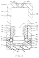
- la figure 1 présente une vue en coupe axiale d'un dispositif avertisseur de sous-gonflage, le pneumatique n'étant pas gonflé ;
- la figure 2 est une vue en coupe similaire à la figure 1, le pneumatique étant à la pression seuil de gonflage ;
- la figure 3 présente une vue en coupe axiale d'un second dispositif avertisseur de sous-gonflage équipé d'un moyen de limitation de la pression au gonflage, le pneumatique étant à sa pression nominale de gonflage ;
- la figure 4 est une vue en coupe axiale d'un dispositif avertisseur de sous-gonflage équipé d'un moyen d'alerte visuelle du déblocage de la masse mobile ;
- la figure 5 représente une vue en coupe d'un second mode de réalisation selon l'invention ;
- la figure 6 est une vue selon A en coupe tel qu'indiqué à la figure 5 du moyen de verrouillage de la masse mobile du second mode de réalisation ;
- la figure 7 présente un schéma d'installation du système avertisseur de sous-gonflage sur un essieu de véhicule.
- FIG. 1 shows a view in axial section of an under-inflation warning device, the tire not being inflated;
- FIG. 2 is a sectional view similar to FIG. 1, the tire being at the inflation threshold pressure;
- FIG. 3 shows a view in axial section of a second under-inflation warning device equipped with means for limiting the inflation pressure, the tire being at its nominal inflation pressure;
- Figure 4 is an axial sectional view of an under-inflation warning device equipped with a visual alert means of the release of the movable mass;
- Figure 5 shows a sectional view of a second embodiment according to the invention;
- Figure 6 is a view along A in section as shown in Figure 5 of the movable mass locking means of the second embodiment;
- FIG. 7 shows a diagram of installation of the under-inflation warning system on a vehicle axle.
Un exemple de réalisation de l'invention est représenté à la figure 1. Le dispositif avertisseur de sous-gonflage 1 comprend un corps fixe 10, une masse mobile 20 et un moyen de verrouillage 30 de ladite masse mobile 20.An exemplary embodiment of the invention is shown in FIG. 1. The under-
Le corps fixe 10, cylindrique, comporte une cavité interne où se déplace la masse mobile 20. Cette masse mobile 20 sépare ladite cavité interne en deux chambres 11 et 12. La chambre 11 est pneumatiquement reliée au pneumatique par l'intermédiaire du conduit 13, elle est donc pressurisée à la pression de gonflage dudit pneumatique. La chambre 12 est reliée à l'atmosphère par le conduit 16, sa pression interne est donc en permanence la pression atmosphérique.The fixed
Le dispositif 1 peut optionnellement être utilisé pour gonfler le pneumatique. Dans ce cas, la chambre 11 comporte un second conduit 14 équipé d'une valve anti-retour 15 s'opposant au dégonflage du pneumatique. Pour éviter un dégonflage accidentel du pneumatique en cas de fuite de la chambre 11 et lorsque le dispositif 1 est utilisé pour le gonflage, la liaison pneumatique entre le dispositif 1 et le pneumatique peut être équipée d'une valve anti-retour 131. Cette valve 131 se place en un point quelconque de ladite liaison par exemple au niveau du conduit 13 comme sur les figures 1 à 4. Cependant, on la met préférentiellement au niveau de la valve de la jante dudit pneumatique.The
La masse mobile 20, à symétrie axiale, a une section axiale en forme de U. Le fond 21 et les barres 22 du U forment une cavité 23 à l'intérieur de ladite masse mobile 20. Le joint 24 assure l'étanchéité entre les deux chambres 11 et 12. Le moyen de verrouillage 30 de la masse mobile 20 comprend :
- deux
billes 31 placées symétriquement dans la paroi de la masse mobile 20 orientée selon l'axe de déplacement, de diamètre supérieur à l'épaisseur de ladite paroi et dont les logements 32 les autorisent à venir tangenter les surfaces intérieure et extérieure de ladite paroi de la masse mobile 20 ; les logements 32 ont du côté de la cavité 23 un diamètre extérieur inférieur à celui des billes 31 de sorte qu'elles ne puissent pas quitter lesdits logements 32 ; un évidement 33 réalisé de préférence circonférentiellement dans la paroi intérieure du corps fixe 10 à une position telle qu'elle permette auxdites billes 31 de s'incruster à l'intérieur lorsque la masse mobile 20 est plaquée contre le fond du corps fixe 10 du côté de la chambre atmosphérique 12 et lorsque lesdites billes 31 tangentent la surface intérieure de la paroi de ladite masse mobile 20 (figure 2) ;une membrane élastique 34 reliée de façon étanche à l'extrémité 35 de la paroi de la masse mobile 20 orientée selon l'axe de déplacement, du côté de la chambre 11 pressurisée ;ladite membrane élastique 34 est terminée par une pièce de blocage 36 dont la géométrie extérieure est adaptée à celle du fond 21 de la masse mobile 20 avec une hauteur telle que, placée contre le fond 21 de ladite masse mobile 20, elle recouvre les logements 32 des billes (figure 2) ; la pièce de blocage 36 comprendun chanfrein 37 ;le conduit 25 traverse le fond 21 de la masse mobile 20 et ramène à la pression atmosphérique la partie de la cavité 23 située entre la pièce de blocage 36 et le fond 21 de la masse mobile 20.
- two
balls 31 placed symmetrically in the wall of themovable mass 20 oriented along the axis of movement, of diameter greater than the thickness of said wall and whosehousings 32 allow them to come and tangent the inner and outer surfaces of said wall of the movingmass 20; thehousings 32 have on the side of thecavity 23 an outer diameter smaller than that of theballs 31 so that they cannot leave saidhousings 32; - a
recess 33 preferably made circumferentially in the inner wall of the fixedbody 10 in a position such that it allows saidballs 31 to become embedded inside when the movingmass 20 is pressed against the bottom of the fixedbody 10 on the side from theatmospheric chamber 12 and when saidballs 31 pitch the inner surface of the wall of said mobile mass 20 (FIG. 2); - an
elastic membrane 34 tightly connected to theend 35 of the wall of themovable mass 20 oriented along the axis of movement, on the side of thepressurized chamber 11; saidelastic membrane 34 is terminated by a blockingpiece 36 whose external geometry is adapted to that of the bottom 21 of themovable mass 20 with a height such that, placed against the bottom 21 of saidmovable mass 20, it covers thehousings 32 of the balls (Figure 2); the lockingpiece 36 comprises achamfer 37; theconduit 25 crosses the bottom 21 of the movingmass 20 and brings back to atmospheric pressure the part of thecavity 23 located between the blockingpiece 36 and the bottom 21 of the movingmass 20.
Le corps fixe 10 est réalisé en deux parties 18 et 19 assemblées par collage après l'insertion de la masse mobile 20 et du moyen de verrouillage 30. Le choix des matériaux de ces deux parties 18 et 19 est tel que, lorsque la masse mobile 20 est en position bloquée, le centre de gravité de ladite masse mobile 20 reste décentré par rapport à celui du dispositif 1 du côté de la chambre pressurisée 11.The fixed
Le dispositif avertisseur du sous-gonflage 1 est prévu pour être monté sur le disque de roue d'un pneumatique de telle sorte que, la masse mobile étant en position bloquée, le centre de gravité dudit dispositif 1 soit placé sur l'axe de la roue dudit pneumatique et l'axe de déplacement de la masse mobile 20 soit non-parallèle avec l'axe de rotation de la roue (figure 7). Dans le cas d'une roue classique, les connections pneumatiques sont protégées sous un enjoliveur. On peut aussi prévoir des roues moulées incorporant, dès leur conception, le dispositif 1.The under-
Le fonctionnement du dispositif avertisseur de sous-gonflage 1 est maintenant décrit à l'aide des figures 1 et 2 :
- lors du gonflage :
- sous l'action d'une pression de gonflage supérieure à la pression atmosphérique, et ce, quelle que soit l'orientation du dispositif 1 par rapport à la verticale, la masse mobile 20 est plaquée contre le fond 17 du corps fixe 10 du côté de la chambre 12 à pression atmosphérique et la
membrane élastique 34 se déploie progressivement dans la cavité 23 ; - lorsque la pression de gonflage devient égale à un seuil donné, le chanfrein 37 de la pièce de blocage 36 repousse les deux billes 31 dans leurs logements 32 et les incruste dans l'évidement circonférentiel 33 de la paroi du corps fixe 10 ; la masse mobile 20 est ainsi bloquée (figure 2) ; enfin, à une pression proche de ladite pression seuil, la pièce de blocage 36 est plaquée contre le fond 21 de la masse mobile 20 ;
- sous l'action d'une pression de gonflage supérieure à la pression atmosphérique, et ce, quelle que soit l'orientation du dispositif 1 par rapport à la verticale, la masse mobile 20 est plaquée contre le fond 17 du corps fixe 10 du côté de la chambre 12 à pression atmosphérique et la
- en service :
- lorsque la pression de gonflage devient proche du seuil donné,
la membrane élastique 34 se contracte, la pièce de blocage 36 s'écarte du fond 21 de la masse mobile 20 , et, à la pression seuil, n'incruste plus les deux billes 31 dans l'évidement circonférentiel 33 pratiqué dans la paroi dudit corps fixe 10, la masse mobile 20 est alors libérée et sous l'action des efforts centrifuges dus au roulage du pneumatique et au décalage du centre de gravité de la masse mobile 20 par rapport à l'axe de la roue se décentre rapidement ce qui crée un balourd au niveau de la roue (figure 1).
- lorsque la pression de gonflage devient proche du seuil donné,
- during inflation:
- under the action of an inflation pressure greater than atmospheric pressure, regardless of the orientation of the
device 1 relative to the vertical, themovable mass 20 is pressed against the bottom 17 of the fixedbody 10 on theside chamber 12 at atmospheric pressure and theelastic membrane 34 is gradually deployed in thecavity 23; - when the inflation pressure becomes equal to a given threshold, the
chamfer 37 of the lockingpiece 36 pushes the twoballs 31 back into theirhousings 32 and embeds them in thecircumferential recess 33 of the wall of the fixedbody 10; themobile mass 20 is thus blocked (FIG. 2); finally, at a pressure close to said threshold pressure, the lockingpiece 36 is pressed against the bottom 21 of themovable mass 20;
- under the action of an inflation pressure greater than atmospheric pressure, regardless of the orientation of the
- in service:
- when the inflation pressure becomes close to the given threshold, the
elastic membrane 34 contracts, the blockingpart 36 moves away from the bottom 21 of the movingmass 20, and, at the threshold pressure, no longer encrusts the twoballs 31 in thecircumferential recess 33 formed in the wall of said fixedbody 10, themobile mass 20 is then released and under the action of centrifugal forces due to the rolling of the tire and the offset of the center of gravity of themobile mass 20 relative to the axis of the wheel quickly decenters which creates an imbalance at the level of the wheel (Figure 1).
- when the inflation pressure becomes close to the given threshold, the
A titre d'exemple, la pression nominale de gonflage du pneumatique étant de l'ordre de deux bars, la pression seuil de sécurité peut être choisie égale à 1,5 bars et la pression dite proche à 1,6 bars.By way of example, the nominal inflation pressure of the tire being of the order of two bars, the safety threshold pressure can be chosen to be 1.5 bars and the pressure called close to 1.6 bars.
La pièce de blocage 36 est réalisée de telle sorte que son poids soit très faible pour que son inertie soit négligeable et n'entraîne pas de déverrouillage accidentel à la suite de chocs.The blocking
Le dispositif 1 précédent permet donc de créer un balourd dynamique au niveau de la roue du pneumatique lorsque la pression de gonflage diminue en dessous du seuil de sécurité choisi et ce balourd entraîne des vibrations qui vont à leur tour avertir le conducteur de l'existence du sous-gonflage. C'est un avantage particulièrement intéressant du dispositif 1 que d'interdire tout roulage à une vitesse élevée donc dangereuse car ces vibrations transmises par la direction au conducteur sont insupportables à vitesse élevée tout en n'interdisant pas un roulage à vitesse modérée. La sécurité apportée par ce dispositif 1 est donc bien supérieure à celle liée à une simple alerte au tableau de bord, souvent négligée par les conducteurs.The preceding
Un perfectionnement au mode de réalisation précédent est présenté à la figure 3. Ce dispositif avertisseur de sous-gonflage 2 est équipé d'un moyen de limitation de la pression de gonflage 40, lors du gonflage.An improvement to the previous embodiment is presented in FIG. 3. This under-
Le corps fixe 10 de ce second dispositif avertisseur de sous-gonflage 2 comprend en plus un conduit d'arrivée d'air de gonflage 41 qui peut être obturé par un pointeau 42, une conduite 43 reliant l'arrivée d'air 41 précédente au conduit d'entrée 14 de la chambre pressurisée 11. Le pointeau 42 est prolongé par une tige 44 qui traverse le fond 17 du corps fixe 10 ainsi que le fond 21 de la masse mobile 20 lorsque celle-ci est plaquée contre le fond 17 par la pression de gonflage. Le joint 45 assure l'étanchéité entre la chambre 12 et la conduite 43.The fixed
Le fonctionnement du dispositif avertisseur de sous-gonflage 2 est proche de celui du dispositif 1 pour tout ce qui concerne les conditions de blocage et de libération de la masse mobile 20 en fonction de la pression de gonflage du pneumatique. La seule différence est que la "pression proche" de la pression seuil précédente est maintenant la pression nominale du pneumatique.The operation of the under-
Lors du gonflage du pneumatique à partir de l'arrivée d'air 41, la pression d'arrivée d'air repousse le pointeau 42 et peut ainsi pénétrer dans la chambre 11 puis dans le pneumatique par l'intermédiaire du conduit 13. Après avoir bloqué la masse mobile 20 à la pression seuil de gonflage, la pièce de blocage 36 est appliquée contre l'extrémité de la tige 44 du pointeau 42 et déplace progressivement ledit pointeau 42 jusqu'à la fermeture de l'arrivée d'air 41 qui intervient à la pression nominale de gonflage du pneumatique.When the tire is inflated from the
Un second perfectionnement au mode de réalisation de l'invention consiste à équiper le dispositif avertisseur de sous-gonflage 1 d'un moyen d'alerte du déblocage de la masse mobile 20. La figure 4 en présente un exemple de réalisation. Ce dispositif avertisseur de sous-gonflage 3 est équipé d'un moyen d'alerte visuelle 50 du déblocage de la masse mobile 20.A second improvement to the embodiment of the invention consists in equipping the under-
Le moyen d'alerte visuelle 50 comprend une tige 51 traversant le fond 17 du corps fixe 10 ainsi que le fond 21 de la masse mobile 20, lorsque ladite masse mobile 20 est plaquée contre le fond 17, et terminée, vers l'extérieur du dispositif 3, par une pastille de couleur vive 52. Le déplacement de ladite tige 51 est limité par deux butées 53 et 54 de part et d'autre du fond 17 du corps fixe 10, ainsi que par un ressort de rappel 55 placé entre la butée 53 et le côté intérieur du fond 17.The visual alert means 50 comprises a
Lorsque la pression de gonflage du pneumatique est supérieure à la pression seuil et ainsi la masse mobile 20 est bloquée, la pièce de blocage 36 appuie sur l'extrémité 56 interne de la tige 51 et repousse vers l'extérieur du dispositif 3 la pastille 52. Ladite pastille 52 est complètement sortie lorsque la pièce de blocage 36 est plaquée contre le fond 21 de la masse mobile 20, soit quand la pression de gonflage est égale à la "pression proche" précédente. Lorsque la pression de gonflage diminue en dessous de cette "pression proche" du seuil de gonflage précédent, la membrane élastique 34 se contracte, la pièce de blocage 36 s'écarte du fond 17 du corps fixe et ainsi permet au ressort de rappel 55 de ramener vers l'intérieur la tige 51, la pastille 52 est alors cachée dans l'évidement 57. Cette pastille 52 est donc un témoin du gonflage correct du pneumatique et son retrait indique une pression insuffisante, que la masse mobile 20 se soit décentrée ou non.When the inflation pressure of the tire is higher than the threshold pressure and thus the moving
Les figures 5 et 6 présentent un second mode de réalisation selon l'invention. Le dispositif 4 comporte un corps fixe 71 tubulaire disposé en spirale autour du point O. A l'intérieur du corps fixe 71, peut se déplacer une bille 72 qui est la masse mobile. A l'extrémité du corps fixe 71 la plus proche du point O, à une distance Ra, se trouve un dispositif de verrouillage (90) de la bille 72. Ce dispositif de verrouillage (figure 6) comprend deux chambres 73 et 74 séparées par une membrane élastique étanche 75. La chambre 73 est reliée au pneumatique par l'intermédiaire du conduit 76 et est donc à la pression de gonflage du pneumatique. La chambre 74 est, elle, en communication avec le corps fixe 71 par le conduit 77, sa pression est ainsi normalement égale à la pression atmosphérique. Une tige 78 est fixée à la membrane élastique 75 et est poussée à travers l'orifice 79 dans le corps fixe 71 lorsque la différence de pression entre les deux chambres 73 et 74 est suffisante venant ainsi bloquer tout déplacement de la bille 72.Figures 5 and 6 show a second embodiment according to the invention. The
Une masse 80 est placée du côté du corps fixe 71 le plus éloigné du point O, à une distance Rb, pour équilibrer le dispositif 4 et assurer que, la bille 72 étant en position bloquée, son centre de gravité se trouve en O.A
Ce dispositif 4 peut avantageusement être aussi utilisé pour gonfler le pneumatique au moyen d'une valve 81 placée à l'extrémité du corps fixe 71 la plus éloignée du point O et d'un conduit 82 reliant les deux chambres 73 et 74 équipé d'une valve anti retour 83.This
Lors du gonflage, le flux d'air traversant le corps fixe 71 plaque la bille contre l'extrémité dudit corps fixe 71 la plus proche du point O et, dès que le pneumatique est correctement gonflé, l'ouverture de la valve 81 ramène la pression dans la chambre 73 à la pression atmosphérique, la chambre 74 restant à la pression de gonflage du pneumatique. La différence de pression entre les deux chambres déforme la membrane 75, repousse la tige 78 dans le corps fixe 71 et bloque la bille 72.During inflation, the air flow passing through the fixed
La membrane 75 est étalonnée pour libérer la bille 72 dès que la pression de gonflage devient inférieure à une pression seuil donnée. Les forces centrifuges dues au roulage déplacent alors immédiatement la bille 72 jusqu'à l'autre extrémité du corps fixe 71 à cause de la différence de rayon. Comme précédemment, ce déplacement entraîne l'apparition d'un balourd dynamique sensible par le conducteur.The
Comme précédemment, ce dispositif 4 est prévu pour être monté sur une roue de pneumatique, entre la jante et le disque de roue, en utilisant des moyens de montage adaptés et connus, de telle sorte que, la bille 72 étant en position bloquée, son centre de gravité soit placé sur l'axe de ladite roue.As before, this
Un autre perfectionnement de l'invention consiste à utiliser l'un quelconque des dispositifs avertisseurs de sous-gonflage 1, 2, 3, 4, précédents en combinaison avec un capteur de vibrations 61 placé sur le porte-roue 62 de la roue du pneumatique.Another improvement of the invention consists in using any of the preceding under-
La figure 7 présente les éléments de suspension d'une roue directrice : porte-roue 62, triangle inférieur de suspension 63, triangle supérieur de suspension 64, biellette de direction 65 et ensemble 60 pneumatique et roue équipée d'un dispositif avertisseur de sous-gonflage 1, 2, 3 ou 4. Le capteur de vibrations 61 peut être placé sur l'un quelconque des éléments de suspension du véhicule : triangle inférieur 63, triangle supérieur 64, biellette de direction 65 et porte-roue 62. La disposition sur le porte-roue 62 est cependant préférable car les informations transmises par le capteur 61 sont le moins filtrées. Les mesures du capteur 61 sont transmises à un boîtier central 66 relié aux quatre systèmes avertisseurs 5 du véhicule. Les mesures sont alors analysées et les alertes transmises au conducteur par des moyens connus.FIG. 7 shows the suspension elements of a steerable wheel:
La détection aisée du balourd dynamique induit par les dispositifs avertisseurs de sous-gonflage 1, 2, 3, 4, précédents par le capteur de vibrations 61 autorise la diminution du seuil de balourd détectable et ainsi une miniaturisation desdits dispositifs avertisseurs 1, 2, 3, 4.The easy detection of the dynamic unbalance induced by the under-
Claims (14)
- A device (1, 2, 3, 4) for warning of the under-inflation of a pneumatic tyre, to be mounted on the wheel of said tyre, characterised in that it creates an imbalance in said wheel when the inflation pressure of the tyre is below a given threshold.
- A device (1, 2, 3, 4) for warning of the under-inflation of a pneumatic tyre according to Claim 1, characterised in that it comprises means for off-centring a centrifugal mass (20) when the inflation pressure of said tyre is below a given threshold.
- A device (1, 2, 3) for warning of the under-inflation of a pneumatic tyre according to Claim 2, characterised in that the off-centring means comprises:- a stationary element (10) having two chambers (11, 12) separated by a centrifugal mass (20), the first of said chambers (11) being connected to the tyre and having a pressure equal to the inflation pressure of said tyre, and the second (12) being at atmospheric pressure;- a means (30) for blocking said contrifugal mass (20) such that said centrifugal mass (20) is blocked when the inflation pressure of the tyre is greater than a given threshold, and is freed so as to be able to become off-centred when the inflation pressure is less than said threshold.
- A device (1, 2, 3) for warning of the under-inflation of a pneumatic tyre according to Claim 3, characterised in that, the centrifugal mass (20) being in the blocked position, the centre of gravity of said centrifugal mass (20) is offset relative to the centre of gravity of the device (1) on the side of the pressurised chamber (11).
- A device (1, 2, 3) for warning of the underinflation of a pneumatic tyre according to Claim 4, characterised in that the centrifugal mass (20) has, in a plane including the axis of displacement, a U-shaped straight section, and in that the blocking means (30) of the centrifugal mass (20) comprises:- at least one ball (31), placed in the wall of the centrifugal mass (20) which extends along the axis of displacement, and with a diameter greater than the thickness of said wall, the housing (32) of which makes it possible for the ball to form a tangent internally and externally to said wall of the centrifugal mass (20);- at least one recess (33) made in the wall of the stationary element (10) at such a position that it enables said ball (31) can be embedded on the inside when the centrifugal mass (20) is flattened against the bottom (17) of the stationary element (1) on the side of the atmospheric chamber (12) and when said ball (31) is tangent to the inside surface of the wall of said centrifugal mass (20);- an elastic membrane (34) connected in an airtight manner to the ends (35) of the centrifugal mass (20), on the side of the chamber (11) the internal pressure of which is the inflation pressure, and ended by a blocking part (36) the outside geometry of which is matched to that of the bottom (21) of the centrifugal mass (20), having a height such that, when it is placed against the bottom (21) of said centrifugal mass (20), it covers the housing (32) of the ball (31).
- A device (2) for warning of the under-inflation of a pneumatic tyre according to one of Claims 1 to 5, characterised in that it includes a means (40) for limiting the inflation pressure of said tyre during inflation.
- A device (2) for warning of the under-inflation of a pneumatic tyre according to Claims 5 and 6, characterised in that the blocking part (36) of the centrifugal mass (20) comes to rest on the end of a rod (44) the other end of which ends in a needle valve (42) for closing of the duct (41) for intake of the inflation air of the tyre, and thus blocks said duct (41) when the inflation pressure reaches the nominal pressure of said tyre.
- A device (3) for warning of the under-inflation of a pneumatic tyre according to one of Claims 3 to 7, characterised in that it comprises a means (50) for warning of the freeing of the centrifugal mass (20).
- A device (4) for warning of the under-inflation of a pneumatic tyre according to Claim 2, characterised in that the off-centring means comprises:- a tubular stationary element (71) placed spirally around a point O in which a mobile element (72) can be displaced and which is connected, at its end closest to said point O, to a chamber (73) connected to the tyre and having a pressure equal to the inflation pressure of said tyre;- a means (90) for blocking said centrifugal mass (72) such that said centrifugal mass (72) is blocked when the inflation pressure of the tyre is greater than a given threshold, and is freed so as to be able to become off-centred when the inflation pressure is less than said threshold.
- A system for warning of the under-inflation of a pneumatic tyre, characterised in that the device (1, 2, 3) according to one of Claims 1 to 8 is mounted on the wheel disc of a tyre such that, the centrifugal mass (20) being in the blocked position, the centre of gravity of said device (1, 2, 3) is placed on the axis of the wheel of said tyre.
- A system for warning of the under-inflation of a pneumatic tyre, characterised in that the device (4) according to one of Claims 1, 2 and 9 is mounted between the rim and the wheel disc of a tyre such that, the centrifugal mass (72) being in the blocked position, the centre of gravity of said device (4) is placed on the axis of the wheel of said tyre.
- A system (5) for warning of the under-inflation of a pneumatic tyre, characterised in that the device (1, 2, 3, 4) according to one of Claims 1 to 9 is used according to one of Claims 10 and 11 in combination with a vibration sensor (61) placed on the wheel carrier (62) of the wheel of said tyre.
- A wheel comprising a device according to any one of Claims 1 to 9.
- A wheel according to Claim 13, characterised in that the centre of gravity of the device (1, 2, 3, 4) for warning of the under-inflation of a pneumatic tyre is placed on the axis of said wheel when the centrifugal mass of said device (1, 2, 3, 4) is in the blocked position.
Priority Applications (5)
| Application Number | Priority Date | Filing Date | Title |
|---|---|---|---|
| FR9116154A FR2685257B1 (en) | 1991-12-23 | 1991-12-23 | DEVICE AND SYSTEM FOR WARNING OF UNDER-INFLATION OF A TIRE AND SPECIALLY DEVELOPED WHEEL. |
| JP4342755A JPH05246219A (en) | 1991-12-23 | 1992-12-22 | Device for warning of tire under-inflation and its system, and specially developed wheel |
| US07/995,043 US5359886A (en) | 1991-12-23 | 1992-12-22 | Device for warning of tire underinflation by creating imbalance |
| DE1993606543 DE69306543T2 (en) | 1993-01-15 | 1993-01-15 | Warning device and system for negative tire pressure and specially designed wheel |
| EP93100542A EP0606511B1 (en) | 1991-12-23 | 1993-01-15 | Warning device and system for underinflated tyres and a specially developed wheel therefore |
Applications Claiming Priority (2)
| Application Number | Priority Date | Filing Date | Title |
|---|---|---|---|
| FR9116154A FR2685257B1 (en) | 1991-12-23 | 1991-12-23 | DEVICE AND SYSTEM FOR WARNING OF UNDER-INFLATION OF A TIRE AND SPECIALLY DEVELOPED WHEEL. |
| EP93100542A EP0606511B1 (en) | 1991-12-23 | 1993-01-15 | Warning device and system for underinflated tyres and a specially developed wheel therefore |
Publications (2)
| Publication Number | Publication Date |
|---|---|
| EP0606511A1 EP0606511A1 (en) | 1994-07-20 |
| EP0606511B1 true EP0606511B1 (en) | 1996-12-11 |
Family
ID=26133047
Family Applications (1)
| Application Number | Title | Priority Date | Filing Date |
|---|---|---|---|
| EP93100542A Expired - Lifetime EP0606511B1 (en) | 1991-12-23 | 1993-01-15 | Warning device and system for underinflated tyres and a specially developed wheel therefore |
Country Status (4)
| Country | Link |
|---|---|
| US (1) | US5359886A (en) |
| EP (1) | EP0606511B1 (en) |
| JP (1) | JPH05246219A (en) |
| FR (1) | FR2685257B1 (en) |
Families Citing this family (13)
| Publication number | Priority date | Publication date | Assignee | Title |
|---|---|---|---|---|
| US5473938A (en) * | 1993-08-03 | 1995-12-12 | Mclaughlin Electronics | Method and system for monitoring a parameter of a vehicle tire |
| US5540092A (en) | 1994-10-31 | 1996-07-30 | Handfield; Michael | System and method for monitoring a pneumatic tire |
| US5825286A (en) * | 1995-05-08 | 1998-10-20 | Semisystems, Inc. | Vehicular data collection and transmission system and method |
| US5838229A (en) * | 1995-07-18 | 1998-11-17 | Schrader-Bridgeport International, Inc. | Remote tire pressure monitoring system employing coded tire identification and radio frequency transmission and enabling recalibration upon tire rotation or replacement |
| US8266465B2 (en) | 2000-07-26 | 2012-09-11 | Bridgestone Americas Tire Operation, LLC | System for conserving battery life in a battery operated device |
| US7161476B2 (en) | 2000-07-26 | 2007-01-09 | Bridgestone Firestone North American Tire, Llc | Electronic tire management system |
| US6672148B2 (en) * | 2001-07-09 | 2004-01-06 | The Goodyear Tire & Rubber Company | Method of improving steering performance robustness utilizing mass non-uniformity in tire/wheel |
| US6668635B2 (en) * | 2001-07-09 | 2003-12-30 | The Goodyear Tire & Rubber Company | Method of improving steering performance robustness utilizing dimensional non-uniformity in tire/wheel |
| US6606902B2 (en) * | 2001-07-09 | 2003-08-19 | The Goodyear Tire & Rubber Company | Method of improving steering performance robustness utilizing stiffness non-uniformity in tire/wheel |
| JP4569309B2 (en) * | 2004-07-30 | 2010-10-27 | トヨタ自動車株式会社 | Wheel |
| JP5171389B2 (en) * | 2008-05-22 | 2013-03-27 | 曙ブレーキ工業株式会社 | Pressure alarm device and pressure alarm system |
| US8464580B2 (en) * | 2010-08-05 | 2013-06-18 | Daniel Paul | Apparatus for maintaining tire pressure |
| DE102018206402B4 (en) * | 2018-04-25 | 2021-08-19 | Audi Ag | Wheel suspension for a motor vehicle and a corresponding motor vehicle |
Family Cites Families (6)
| Publication number | Priority date | Publication date | Assignee | Title |
|---|---|---|---|---|
| US3129690A (en) * | 1963-06-28 | 1964-04-21 | William O Nygard | Warning device |
| US3756190A (en) * | 1972-02-18 | 1973-09-04 | H Kendall | Pressure responsive device for indicating the magnitude of pressure changes |
| US4082056A (en) * | 1976-02-17 | 1978-04-04 | Eaton Corporation | Pressure change indicator |
| DE3541494A1 (en) * | 1985-11-23 | 1987-05-27 | Continental Gummi Werke Ag | Device for monitoring the tyre pressure on vehicles |
| US4742712A (en) * | 1986-03-20 | 1988-05-10 | Kabushiki Kaisha Tokai Rika Denki Seisakusho | System for monitoring air pressure of motor vehicle |
| US4943798A (en) * | 1989-08-26 | 1990-07-24 | Wayman Wayne | Large truck remote wheel trouble warning system |
-
1991
- 1991-12-23 FR FR9116154A patent/FR2685257B1/en not_active Expired - Fee Related
-
1992
- 1992-12-22 JP JP4342755A patent/JPH05246219A/en active Pending
- 1992-12-22 US US07/995,043 patent/US5359886A/en not_active Expired - Lifetime
-
1993
- 1993-01-15 EP EP93100542A patent/EP0606511B1/en not_active Expired - Lifetime
Also Published As
| Publication number | Publication date |
|---|---|
| JPH05246219A (en) | 1993-09-24 |
| EP0606511A1 (en) | 1994-07-20 |
| US5359886A (en) | 1994-11-01 |
| FR2685257A1 (en) | 1993-06-25 |
| FR2685257B1 (en) | 1994-02-11 |
Similar Documents
| Publication | Publication Date | Title |
|---|---|---|
| EP0606511B1 (en) | Warning device and system for underinflated tyres and a specially developed wheel therefore | |
| EP2379353A1 (en) | Alarm method for indicating the wear of a tyre with a furrow | |
| EP0679544B1 (en) | Run-flat device for vehicle | |
| EP1106388B1 (en) | Industrial vehicle wheel with a valve, which opens outside the disk | |
| WO2007039608A1 (en) | Method and device for measuring a tyre inflation pressure by means of a stress sensor | |
| WO1998047728A1 (en) | Safety insert generating a transverse dither signal and device for sensing the tyre weight resting on the insert | |
| FR2497154A1 (en) | TIRE DEGREEING NOZZLE FOR MOTOR VEHICLES | |
| FR2888779A1 (en) | Tread support for vehicle tire, has recess for electronic module, located in blocking part which serves to block bead of tire on wheel seat, and support part serving to support load of tire during flat running | |
| EP2303609B1 (en) | Purging device for assembled unit and method of deflating an assembled unit | |
| EP0041511B1 (en) | Reference pressure comparator device for a vehicle tyre with remote display | |
| EP0775601B1 (en) | Tyre with a safety ring incorperating a pressure sensor | |
| FR2903752A1 (en) | Snap-in type inflation valve for use in tire-and-wheel assembly for passenger car, has annular hollow space that is formed in portion of valve located between two planes for separating tube from valve base | |
| EP0072768B1 (en) | Vehicle wheel with manometer | |
| WO2010116095A1 (en) | Evaluating a peripheral deformation of a tire during use | |
| EP0844111B1 (en) | Security insert with emergency signalling function | |
| WO2002066268A1 (en) | Controlled pneumatic valve | |
| EP1049592B1 (en) | Alarm safety insert | |
| FR2531912A1 (en) | DEVICE FOR DETECTING AND SIGNALING WHEEL DEFECT | |
| FR3074122B1 (en) | DEVICE FOR CONNECTING THE GROUND OF A VEHICLE COMPRISING AN ANGULAR POSITION DETECTION UNIT OF A WHEEL | |
| FR2762260A1 (en) | Motor vehicle tyre safety insert | |
| FR2579323A1 (en) | Magnetic device for checking tyre pressures | |
| FR2775634A1 (en) | Run-flat tyre safety insert generating alarm signals | |
| FR2774335A1 (en) | Safety alarm for insertion in vehicle tyres to indicate under-inflation | |
| FR2877612A1 (en) | Sensor case and valve fixation device for e.g. private car, has excrescence arranged aside tubular part section and penetrating inside excrescence placed aside zone of valve`s end portion, in order to fix valve opposite to intermediate part | |
| FR2774334A1 (en) | Run-flat tyre safety insert generating alarm signals |
Legal Events
| Date | Code | Title | Description |
|---|---|---|---|
| PUAI | Public reference made under article 153(3) epc to a published international application that has entered the european phase |
Free format text: ORIGINAL CODE: 0009012 |
|
| 17P | Request for examination filed |
Effective date: 19930115 |
|
| AK | Designated contracting states |
Kind code of ref document: A1 Designated state(s): BE DE ES FR GB IT |
|
| GRAG | Despatch of communication of intention to grant |
Free format text: ORIGINAL CODE: EPIDOS AGRA |
|
| 17Q | First examination report despatched |
Effective date: 19960318 |
|
| GRAH | Despatch of communication of intention to grant a patent |
Free format text: ORIGINAL CODE: EPIDOS IGRA |
|
| GRAH | Despatch of communication of intention to grant a patent |
Free format text: ORIGINAL CODE: EPIDOS IGRA |
|
| GRAA | (expected) grant |
Free format text: ORIGINAL CODE: 0009210 |
|
| AK | Designated contracting states |
Kind code of ref document: B1 Designated state(s): BE DE ES FR GB IT |
|
| PG25 | Lapsed in a contracting state [announced via postgrant information from national office to epo] |
Ref country code: IT Free format text: LAPSE BECAUSE OF FAILURE TO SUBMIT A TRANSLATION OF THE DESCRIPTION OR TO PAY THE FEE WITHIN THE PRE;WARNING: LAPSES OF ITALIAN PATENTS WITH EFFECTIVE DATE BEFORE 2007 MAY HAVE OCCURRED AT ANY TIME BEFORE 2007. THE CORRECT EFFECTIVE DATE MAY BE DIFFERENT FROM THE ONE RECORDED.SCRIBED TIME-LIMIT Effective date: 19961211 Ref country code: ES Free format text: THE PATENT HAS BEEN ANNULLED BY A DECISION OF A NATIONAL AUTHORITY Effective date: 19961211 |
|
| REF | Corresponds to: |
Ref document number: 69306543 Country of ref document: DE Date of ref document: 19970123 |
|
| PG25 | Lapsed in a contracting state [announced via postgrant information from national office to epo] |
Ref country code: BE Effective date: 19970131 |
|
| GBT | Gb: translation of ep patent filed (gb section 77(6)(a)/1977) |
Effective date: 19970125 |
|
| BERE | Be: lapsed |
Owner name: CIE GENERALE DES ETS MICHELIN-MICHELIN & CIE Effective date: 19970131 |
|
| PLBE | No opposition filed within time limit |
Free format text: ORIGINAL CODE: 0009261 |
|
| STAA | Information on the status of an ep patent application or granted ep patent |
Free format text: STATUS: NO OPPOSITION FILED WITHIN TIME LIMIT |
|
| 26N | No opposition filed | ||
| PGFP | Annual fee paid to national office [announced via postgrant information from national office to epo] |
Ref country code: GB Payment date: 19990114 Year of fee payment: 7 |
|
| PGFP | Annual fee paid to national office [announced via postgrant information from national office to epo] |
Ref country code: DE Payment date: 19990217 Year of fee payment: 7 |
|
| PG25 | Lapsed in a contracting state [announced via postgrant information from national office to epo] |
Ref country code: GB Free format text: LAPSE BECAUSE OF NON-PAYMENT OF DUE FEES Effective date: 20000115 |
|
| GBPC | Gb: european patent ceased through non-payment of renewal fee |
Effective date: 20000115 |
|
| PG25 | Lapsed in a contracting state [announced via postgrant information from national office to epo] |
Ref country code: DE Free format text: LAPSE BECAUSE OF NON-PAYMENT OF DUE FEES Effective date: 20001101 |
|
| PGFP | Annual fee paid to national office [announced via postgrant information from national office to epo] |
Ref country code: FR Payment date: 20100223 Year of fee payment: 18 |
|
| REG | Reference to a national code |
Ref country code: FR Ref legal event code: ST Effective date: 20110930 |
|
| PG25 | Lapsed in a contracting state [announced via postgrant information from national office to epo] |
Ref country code: FR Free format text: LAPSE BECAUSE OF NON-PAYMENT OF DUE FEES Effective date: 20110131 |