EP0605821A1 - Exhaust gases extraction hood - Google Patents
Exhaust gases extraction hood Download PDFInfo
- Publication number
- EP0605821A1 EP0605821A1 EP93120268A EP93120268A EP0605821A1 EP 0605821 A1 EP0605821 A1 EP 0605821A1 EP 93120268 A EP93120268 A EP 93120268A EP 93120268 A EP93120268 A EP 93120268A EP 0605821 A1 EP0605821 A1 EP 0605821A1
- Authority
- EP
- European Patent Office
- Prior art keywords
- exhaust gas
- gas detection
- detection hood
- sink
- hood according
- Prior art date
- Legal status (The legal status is an assumption and is not a legal conclusion. Google has not performed a legal analysis and makes no representation as to the accuracy of the status listed.)
- Granted
Links
Images

Classifications
-
- B—PERFORMING OPERATIONS; TRANSPORTING
- B08—CLEANING
- B08B—CLEANING IN GENERAL; PREVENTION OF FOULING IN GENERAL
- B08B15/00—Preventing escape of dirt or fumes from the area where they are produced; Collecting or removing dirt or fumes from that area
- B08B15/02—Preventing escape of dirt or fumes from the area where they are produced; Collecting or removing dirt or fumes from that area using chambers or hoods covering the area
-
- B—PERFORMING OPERATIONS; TRANSPORTING
- B08—CLEANING
- B08B—CLEANING IN GENERAL; PREVENTION OF FOULING IN GENERAL
- B08B15/00—Preventing escape of dirt or fumes from the area where they are produced; Collecting or removing dirt or fumes from that area
Definitions
- the invention relates to an exhaust gas detection hood for detecting contaminated air or other gases, in particular from elongated sources, in which the hood is delimited by two mutually parallel end faces and has a jacket running between them, in which at least one stabilized swirl flow is maintained.
- a ridge ventilation with at least one longitudinal roof rider is provided in the ridge of the hall, which is provided with air outlets opening outwards.
- Roof attachments of this type are known in a wide variety of forms, and the individual embodiments are essentially concerned with ensuring that indoor air is unaffected by the weather. In such systems, these emerging contaminants initially pass into the air in the hall and are released into the free atmosphere with the air in the hall, possibly considerably diluted. This involves an air change that can possibly be tolerated in hot factories, but which leads to drafts and creates additional heating problems in halls without significant heat sources, and which generally does not allow the exhaust air to be cleaned.
- the dynamic pressure directly associated with the high peripheral speed allows the static pressure in the area of the inflow opening to drop because of the constancy of the total pressure, so that the desired effect of suctioning off and detecting the impurities released in the area of the inflow opening is ensured.
- suction air currents can be generated, provided the width of the hood does not exceed a dimension dependent on the swallowing capacity of the frontal depressions.
- such an exhaust gas detection hood requires a suction area that limits the flow in order to force the desired defined suction flow, which, however, is not possible in free space.
- the invention comes in, which is based on the task of further developing a generic exhaust gas detection hood in such a way that it can be used for any lengths , can advantageously be used as an "overhead hood".
- the hood should be simple and economical to manufacture, easy to maintain and reliable.
- the hood is provided with sink tubes which are aligned radially to the jacket surface and have sink openings concentric to the jacket surface, the sink tubes inserted into the hood being connected to a suction system.
- each of the end faces has two flow sinks and in that further flow sinks are provided at intervals therefrom, which are introduced radially into the partial cylinder, the sink pipes being provided with inflow openings which are coaxial with the cylinder producing the hood, flow conditions are created which ensure a continuous swirl flow over the entire width of the exhaust gas detection hood.
- These sink pipes are connected to suction systems, via which the air to be extracted is sucked out of the center of the stabilized swirl flow in such a way that this flow is maintained in a stable manner.
- These sink tubes each represent a double sink, since the inflow openings coaxial to the cylinder are open on both sides.
- the cross section of the jacket is partially cylindrical; In another embodiment, it is polygonal, and in both forms the partial area corresponding to the outflowing flow can be drawn in to the central axis of the exhaust gas detection hood.
- the spiral formation of at least this partial area is advantageous; in the case of the polygonal shape, the last section of the polygon lying in the direction of the flow is advantageously bent inwards, so that in both cases the desired restriction of the flow before entry is reached in the area of the suction opening.
- the inflow openings of the flow sinks expediently have conventional inlet nozzles provided with curves, which are inserted into the end faces or the sink pipes. These rounded inlet nozzles reduce the inflow losses of each of these sinks and thus reduce the energy required to promote the extracted air flow.
- the suction systems can be provided individually for each of these sink pipes, it being advantageous if the connections are made via flexible connecting lines.
- the suction devices can also be set up in groups.
- all or some of the sink pipes combined in groups are connected to a suction device.
- a common suction channel is provided for all drain pipes or for the drain pipe group.
- the channel cross-section is designed such that the cross-section increases by a certain amount each time one of the sink pipes is introduced, this cross-sectional increase being such that the Flow velocity in the entire suction channel is essentially the same.
- the sink tubes are advantageously arranged at equidistant distances from the respectively adjacent or opposite the respective adjacent end wall. This arrangement provides a symmetry which allows the individual suction flows of the individual sinks (end faces) or double sinks (sink pipes) to be compared with one another in a simple manner.
- the outer surface of the hood is formed by two penetrating cylinders, the penetration being such that the center points of the cylinders lie outside the respective other cylinder and that the openings of the cylinders complement one another to form a suction opening.
- Such an exhaust gas detection hood does not require an additional flow guide surface and it can easily be used as an "overhead hood". Since it can be extended to any length due to the additional sinks, it also allows exhaust gases or gases from elongated sources to be effectively captured and extracted.
- the source is advantageously parallel to the axis of the exhaust gas detection hood and symmetrical to a vertical plane running through its center.
- the jacket surrounding the hood volume is formed by two penetrating cylinders, which are equally open in the lower area of each of these cylinders, the air flowing into the suction opening is forced into a double swirl flow, the two swirl flows being afflicted in opposite directions and mutually stabilize.
- the arrangement of the two hoods, which are arranged in mirror image to one another, is important, the two swirling currents being superimposed in the area of penetration. With these opposing swirl flows it is achieved that the required suction flow is formed on both sides of the center plane of the hood arrangement.
- the opposing swirl flows in the two hoods, which are due to inflow asymmetries, run at a higher rotational speed than the suction speed, so that the dynamic pressure of the swirl flow can lower the static pressure in the inflow area and force the inflow out of the room.
- the inflow is mirror-symmetrical to the longitudinal axis and extends essentially over the entire length of the exhaust gas detection hood.
- the two outer edges of the jacket, which delimit the suction opening are provided with guide surfaces directed into the interior of the cylinders, which narrow the flow cross-section of both cylinders in approximately the same way.
- This constriction of the swirl flows into the areas of their transitions into the inflow opening, which is known per se from DE-OS 39 01 859, accelerates the swirl flow on the one hand and the asymmetry of the inflow on the other enlarged and thus favors the formation of the swirl flow; this narrowing is made equally on both sides.
- the exhaust gas detection hood is arranged to be adjustable in height and is preferably provided with an adjustment drive.
- Their connecting pieces are connected to the suction lines or to the suction channel. It goes without saying that it is irrelevant for the function of the suction hoods whether they are connected to rigid suction tubes or to flexible suction lines.
- the rigid suction pipes are telescopically pushed into one another when the height of the hood changes, for example, or they can be pivoted to compensate for the height difference.
- a certain amount of height difference can be bridged with their flexibility in a simple manner, although increased pipe friction and an associated increased pressure drop have to be accepted.
- the stability increases further. It is advantageous if the constriction is carried out by a straight or a diaphragm rounded in accordance with the flow in such a way that the radius of the flow is reduced by about 25%. This diaphragm also achieves a "pre-direction" of the air flowing in to the inlet opening from the side facing away from the inflow surface, so that the formation and the stability of the swirl flow are also favored from this side.
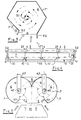
- FIG. 1 shows a highly schematic section of an exhaust gas detection hood in a perspective view with an end plate 6 and a jacket 7 which extends from the end plate 6 in the axial direction and which has a cylindrical cross section in the example shown.
- the end plate 6 is provided (here :) with a sink pipe 3 arranged centrally to the jacket 7, which has an inlet nozzle 3.1, which represents the flow sink and with which exhaust air is taken over in the center of the exhaust gas detection hood and thus a swirl flow is excited.
- a sink pipe 4 is guided axially into the flow through the jacket 7 at a distance from the end plate 6 and is provided with two mutually directed inlet nozzles 4.1, which are coaxial with the inlet nozzles 3.1 of the end plates 6 lie.
- These inlet nozzles 4.1 of the axial sink pipes 4 likewise produce a sink flow, as indicated by the dashed arrows, which stimulates a swirl flow, also indicated by the dashed arrows, with a proportion of air corresponding to the air flowing into the flow sink through the inflow opening 8 of the exhaust gas detection system.
- the hood is sucked in again, as indicated by dashed arrows.
- the swirl flow is not tied to a cylindrical shape of the exhaust gas detection hood.
- the acceleration is distributed over the path covered by the jacket 7.
- the end plate 6 is here (shown for better illustration with a circularly delimited upper part) beyond the suction opening 8, both ends of the jacket 7 being provided with aprons 9.2 which, together with the protruding end plate 6, limit the inflow region to the outside.
- the casing 7 ′′ is designed as a polygon (shown here as a hexagon).
- the exhaust gas detection hood is able to generate and guide a swirl flow (shown in dashed lines).
- a swirl flow shown in dashed lines.
- the end plate 6 is expediently adapted to the polygon, it being able to protrude in the region of the inwardly bent section.
- the two ends of the jacket 7 can be provided with aprons which — as in the case of the spiral jacket 7 ′ - are directed outwards and, together with the projection of the end plate 6, limit the inflow region.
- FIG. 4 shows a longitudinal view of an exhaust gas detection hood with the jacket 7, which extends between the two end plates 6.
- the axial sink tubes 3 for the end plates are guided centrally into these end plates and are provided with inlet nozzles 3.1 on the inflow side.
- Each of the radial sink tubes 4 has two inlet nozzles 4.1, which are directed towards each other.
- the axial drain pipes 3, like the radial drain pipes 4, are connected via the connecting lines 3.2 and 4.2 to an exhaust air collecting duct 2, which in turn is connected to the exhaust air connector 1 is connected to an exhaust air extraction system (not shown).
- a proportion of fresh air corresponding to the air sucked out via the inlet nozzles of the sink pipes is sucked in through the suction opening 8, an inward-facing apron 9.1 pushing the air into the area of the suction opening 8 of the swirl flow inward and accelerating it.
- FIG. 5 shows a special application of the exhaust gas detection hood:
- two opposing swirl flows are generated in a hood which is provided with two end plates, one of which can be seen in the section shown.
- the end plates 6 are provided with the axial sink pipes 3 and radial sink pipes 4 are introduced into the swirl flow, all sink pipes being provided with the corresponding inlet nozzles 3.1 and 4.1, respectively, which have one or two (not shown in more detail) exhaust air collecting duct / channels are connected.
- the two swirl flows which are formed by the inflow of the extracted air into the inflow openings of the sink pipes are in opposite directions, the direction of flow being advantageously chosen such that both swirl flows in the area of the suction opening 8 are directed away from the latter.
- Both edges of the common casing 7 are expediently provided with inward-facing skirts 9.1, which force both swirl flows inwards and accelerate them before they enter the area of the suction opening 8.
- the two coats can also be formed spirally inwards - as indicated by dashed lines.
- the end plates 6 can - as shown - be designed so that their contour represents an envelope of the common jacket 7. It goes without saying that this end plate 6 can also be shaped according to the contour of the common casing 7.
Abstract
Description
Die Erfindung betrifft eine Abgaserfassungshaube zum Erfassen verunreinigter Luft oder anderer Gase insbesondere aus langgestreckten Quellen, bei der die Haube von zwei zueinander parallelen Endflächen begrenzt ist und einen dazwischen verlaufenden Mantel aufweist, in dem mindestens eine stabilisierte Drallströmung aufrecht erhalten ist.The invention relates to an exhaust gas detection hood for detecting contaminated air or other gases, in particular from elongated sources, in which the hood is delimited by two mutually parallel end faces and has a jacket running between them, in which at least one stabilized swirl flow is maintained.
Zur Abführung aufsteigender oder nach oben austretender Abgase einer in einer Halle befindlichen Quelle luftverunreinigender Stoffe wird häufig eine First-Lüftung mit mindestens einem längsverlaufenden Dachreiter im First der Halle vorgesehen, der mit nach außen öffnenden Luftaustritten versehen ist. Derartige Dachaufsätze sind in vielfältigen Formen bekannt, wobei es bei den einzelnen Ausführungsformen im wesentlichen darum geht, eine vom Witterungsgeschehen unbeeinflußte Abführung von Hallenluft zu gewährleisten. Bei derartigen Systemen gehen diese austretenden Verunreinigungen zunächst in die Luft der Halle über und werden mit der Hallenluft, ggf. erheblich verdünnt, in die freie Atmosphäre entlassen. Dabei erfolgt ein Luftwechsel, der möglicherweise in Heißbetrieben toleriert werden kann, der jedoch zu Zugerscheinungen führt und in Hallen ohne bedeutsame Wärmequellen zusätzliche Heizungsprobleme aufwirft, und der in aller Regel keine Reinigung der Abluft zuläßt. Aus diesem Grunde wurde neben einer Kapselung der Quelle (Direkt-Absaugung) bereits versucht, die Grundfläche der Quelle mit einer Erfassungshaube zu überdecken, die dann die aus der Quelle austretenden Verunreinigungen aufnehmen und abführen soll. Diese Absaugung ist dabei auf den Arbeitsprozess auszurichten, so daß die zum Absaugen eingesetzten Absaugehauben die freigesetzten Luftverunreinigungen möglichst vollständig erfassen. Derartige Absaugehauben führen jedoch zu erheblichen Luftströmen, die nur schwer zu bewältigen sind; da diese Luftströme, um den Auflagen zur Reinhaltung der Luft nachzukommen, in nachgeschalteten Abscheidern gereinigt werden müssen. Investitionskosten und Betrieb derartiger Abscheider steigen mit der Größe der Luftströme an, so daß insbesondere großflächige Absaugehauben wegen der nachgeschalteten Abscheider erhebliche Folgekosten bedingen. Haubenausbildungen, bei denen zur Verringerung des abgesaugten Luftstromes lediglich im Randbereich abgesaugt wird, können zwar mit einem geringeren Luftstrom betrieben werden, ihre Erfassung leidet jedoch insbesondere dann, wenn die Luftverunreinigungen stoßweise anfallen oder wenn sie mit hoher kinetischer Anfangsenergie freigesetzt werden.For the removal of ascending or escaping exhaust gases from a source of air-polluting substances located in a hall Often a ridge ventilation with at least one longitudinal roof rider is provided in the ridge of the hall, which is provided with air outlets opening outwards. Roof attachments of this type are known in a wide variety of forms, and the individual embodiments are essentially concerned with ensuring that indoor air is unaffected by the weather. In such systems, these emerging contaminants initially pass into the air in the hall and are released into the free atmosphere with the air in the hall, possibly considerably diluted. This involves an air change that can possibly be tolerated in hot factories, but which leads to drafts and creates additional heating problems in halls without significant heat sources, and which generally does not allow the exhaust air to be cleaned. For this reason, in addition to encapsulating the source (direct suction), attempts have already been made to cover the base area of the source with a detection hood, which is then to take up and remove the contaminants emerging from the source. This extraction must be aligned with the work process so that the extraction hoods used for extraction capture the released air pollution as completely as possible. Such suction hoods, however, lead to considerable air flows that are difficult to manage; since these air flows have to be cleaned in downstream separators in order to comply with the requirements for keeping the air clean. Investment costs and the operation of such separators increase with the size of the air streams, so that, in particular, large-area extraction hoods entail considerable consequential costs because of the downstream separators. Hood designs in which suction is only carried out in the edge area to reduce the extracted air flow can be operated with a lower air flow, but their detection suffers in particular if the air pollution occurs intermittently or if it is released with high kinetic initial energy.
Aus der DE-OS 39 01 859 ist nun eine Erfassunghaube für verunreinigte Luft bekannt, die längs einer horizontalen Ebene einen Absauge-Luftstrom erzeugt, wobei durch die sich zwischen zwei Endflächen erstreckende Haube ein Absaugebereich gegeben ist, dessen Breite von der Entfernung beider Endflächen gegeben ist. Die Einströmöffnung, die sich ebenfalls über die gesamte Breite der Haube erstreckt, kann in ihrer Höhe beliebig gestaltet werden. Wesentlich dabei ist, daß beide Endflächen durch einen, das Gehäuse der Haube vervollständigenden, zylindrischen Teilmantel verbunden sind, wobei die Einströmöffnung in ihrer Höhe kleiner ist, als der Durchmesser dieses Mantels. In dieser Haube bildet sich eine reine Drallströmung aus, die den Gesetzen der Potentialströmung gehorchend, eine gegenüber der Eintrittsgeschwindigkeit der angesaugten Luft relativ hohe Umfangsgeschwindigkeit aufweist. Der mit der hohen Umfangsgeschwindigkeit unmittelbar verbundene dynamische Druck läßt wegen der Konstanz des Gesamtdruckes den statischen Druck im Bereich der Einströmöffnung absinken, so daß der gewünschte Effekt des Absaugens und Erfassens der im Bereich der Einströmöffnung freigesetzten Verunreinigungen gewährleistet ist. Mit einer derartigen Haube lassen sich Absauge-Luftströme erzeugen, sofern die Breite der Haube ein von Schluckvermögen der stirnseitigen Senken abhängiges Maß nicht übersteigt. Darüber hinaus bedarf eine derartige Abgaserfassungshaube eine die Strömung begrenzende Absaugefläche, um die gewünschte definierte Absaugeströmung zu erzwingen, was im freien Raum dagegen nicht gelingt.From DE-OS 39 01 859 is now a detection hood for contaminated Air is known which produces a suction air flow along a horizontal plane, the hood extending between two end faces providing a suction area, the width of which is given by the distance between the two end faces. The height of the inflow opening, which also extends over the entire width of the hood, can be designed as desired. It is essential here that both end faces are connected by a cylindrical partial casing which completes the housing of the hood, the inflow opening being smaller in height than the diameter of this casing. A pure swirl flow is formed in this hood, which, in compliance with the laws of potential flow, has a circumferential speed that is relatively high compared to the entry speed of the intake air. The dynamic pressure directly associated with the high peripheral speed allows the static pressure in the area of the inflow opening to drop because of the constancy of the total pressure, so that the desired effect of suctioning off and detecting the impurities released in the area of the inflow opening is ensured. With such a hood, suction air currents can be generated, provided the width of the hood does not exceed a dimension dependent on the swallowing capacity of the frontal depressions. In addition, such an exhaust gas detection hood requires a suction area that limits the flow in order to force the desired defined suction flow, which, however, is not possible in free space.
Hier setzt die Erfindung ein, der die Aufgabe zugrunde liegt, eine gattungsgemäße Abgaserfassungshaube so weiter zu entwickeln, daß sie für beliebige Längen einsetzbar ist, wobei -in Weiterführung der Aufgabe- auch eine Haube vorgeschlagen werden soll, die ohne an eine Absaugefläche gebunden zu sein, vorteilhaft als "Über-Kopf-Haube" einsetzbar ist. Darüber hinaus soll die Haube einfach und wirtschaftlich herstellbar, leicht zu warten und betriebssicher aufgebaut sein.This is where the invention comes in, which is based on the task of further developing a generic exhaust gas detection hood in such a way that it can be used for any lengths , can advantageously be used as an "overhead hood". In addition, the hood should be simple and economical to manufacture, easy to maintain and reliable.
Die Lösung der Aufgabe beschreiben die im Hauptanspruch enthaltenen Merkmale des Kennzeichens; vorteilhafte Weiterbildungen und bevorzugte Ausführungsformen beschreiben die Unteransprüche.The solution to the problem is described in the features of the license plate contained in the main claim; advantageous further developments and preferred embodiments describe the subclaims.
Nach der Lösung ist die Haube mit radial zur Mantelfläche ausgerichteten Senkenrohren versehen, die konzentrisch zur Mantelfläche Senkenöffnungen aufweisen, wobei die in die Haube eingeführten Senkenrohre an ein Absaugesystem angeschlossen sind. Dadurch, daß jede der Endflächen zwei Strömungssenken aufweist, und daß in Abständen davon weitere Strömungssenken vorgesehen sind, die in Form radial in den Teil-Zylinder eingebracht sind, wobei die Senkenrohre mit Einströmöffnungen versehen sind, die koaxial zu dem die Haube erzeugenden Zylinder liegen, werden Strömungsverhältnisse geschaffen, die eine durchgehende Drallströmung über die gesamte Breite des Abgaserfassungshaube gewährleisten. Diese Senkenrohre sind an Absaugesysteme angeschlossen, über die die abzusaugende Luft aus dem Zentrum der stabilisierten Drallströmung so abgesaugt wird, daß diese Strömung stabil aufrecht erhalten wird. Dabei stellen diese Senkenrohre jeweils eine Doppelsenke dar, da die zum Zylinder koaxialen Einströmöffnungen nach beiden Seiten hin geöffnet sind.According to the solution, the hood is provided with sink tubes which are aligned radially to the jacket surface and have sink openings concentric to the jacket surface, the sink tubes inserted into the hood being connected to a suction system. Characterized in that each of the end faces has two flow sinks and in that further flow sinks are provided at intervals therefrom, which are introduced radially into the partial cylinder, the sink pipes being provided with inflow openings which are coaxial with the cylinder producing the hood, flow conditions are created which ensure a continuous swirl flow over the entire width of the exhaust gas detection hood. These sink pipes are connected to suction systems, via which the air to be extracted is sucked out of the center of the stabilized swirl flow in such a way that this flow is maintained in a stable manner. These sink tubes each represent a double sink, since the inflow openings coaxial to the cylinder are open on both sides.
Nach einer Ausführungsform ist der Querschnitt des Mantels teil-zylindrisch ausgebildet; in einer anderen Ausführungsform ist er polygonal ausgebildet, wobei bei beiden Formen der der auslaufenden Strömung entsprechende Teilbereich zu der Mittelachse der Abgaserfassungshaube eingezogen sein kann. Bei der teil-zylindrischen Form ist dazu die spiralige Ausbildung zumindest dieses Teilbereichs vorteilhaft, bei der polygonalen Ausbildungsform wird vorteilhaft das in Richting der Strömung liegende, letzte Teilstück des Polygons nach innen abgebogen, so daß in beiden Fällen die gewünschte Einengung der Strömung vor dem Eintritt in den Bereich der Absaugeöffnung erreicht wird.According to one embodiment, the cross section of the jacket is partially cylindrical; In another embodiment, it is polygonal, and in both forms the partial area corresponding to the outflowing flow can be drawn in to the central axis of the exhaust gas detection hood. In the case of the partially cylindrical shape, the spiral formation of at least this partial area is advantageous; in the case of the polygonal shape, the last section of the polygon lying in the direction of the flow is advantageously bent inwards, so that in both cases the desired restriction of the flow before entry is reached in the area of the suction opening.
Zweckmäßiger Weise weisen in einer vorteilhaften Weiterbildung die Einströmöffnungen der Strömungssenken übliche, mit Rundungen versehene Einlaufdüsen auf, die in die Endflächen bzw. die Senkenrohre eingesetzt sind. Durch diese gerundeten Einlaufdüsen werden die Einströmverluste jeder dieser Senken verringert und so der Energiebedarf zur Förderung des abgesaugten Luftstroms gesenkt.In an advantageous development, the inflow openings of the flow sinks expediently have conventional inlet nozzles provided with curves, which are inserted into the end faces or the sink pipes. These rounded inlet nozzles reduce the inflow losses of each of these sinks and thus reduce the energy required to promote the extracted air flow.
Die Absaugesysteme können dabei individuell für jede dieser Senkenrohre vorgesehen sein, wobei es vorteilhaft ist, wenn die Anschlüsse über flexible Anschlußleitungen geführt sind. So läßt sich bei der Vielzahl der vorzusehenden Anschlüsse auch ein gruppenweises Aufstellen der Absaugevorrichtungen erreichen. Alternativ dazu werden alle oder einige zu Gruppen zusammengefaßte Senkenrohre an eine Absaugevorrichtung angeschlossen. Dabei wird ein für alle Senkenrohre oder für die Senkenrohr-Gruppe jeweils ein gemeinsamer Absaugekanal vorgesehen. Um die Gleichmäßigkeit der Senken-Absaugung zu gewährleisten und um den Druckverlust im Absaugekanal zu begrenzen, wird der Kanal-Querschnitt so gestaltet, daß sich bei jeder Einführung eines der Senkenrohre der Querschnitt um einen gewissen Betrag vergrößert, wobei diese Querschnittszunahme derart ist, daß die Strömungsgeschwindigkeit im gesamten Absaugekanal im wesentlichen gleich ist. Vorteilhafterweise sind die Senkenrohre in äquidistanten Abständen gegenüber dem jeweils benachbarten bzw.gegenüber der jeweils benachbarten Endwand angeordnet. Durch diese Anordnung ist eine Symmetrie gegeben, die es erlaubt, die einzelnen Absaugeströme der einzelnen Senken (Endflächen) bzw. Doppelsenken (Senkenrohre) in einfacher Weise gegeneinander abzugleichen.The suction systems can be provided individually for each of these sink pipes, it being advantageous if the connections are made via flexible connecting lines. With the multitude of connections to be provided, the suction devices can also be set up in groups. Alternatively, all or some of the sink pipes combined in groups are connected to a suction device. In this case, a common suction channel is provided for all drain pipes or for the drain pipe group. In order to ensure the uniformity of the sink suction and to limit the pressure loss in the suction channel, the channel cross-section is designed such that the cross-section increases by a certain amount each time one of the sink pipes is introduced, this cross-sectional increase being such that the Flow velocity in the entire suction channel is essentially the same. The sink tubes are advantageously arranged at equidistant distances from the respectively adjacent or opposite the respective adjacent end wall. This arrangement provides a symmetry which allows the individual suction flows of the individual sinks (end faces) or double sinks (sink pipes) to be compared with one another in a simple manner.
In einer bevorzugten Ausführungsform ist die Mantelfläche der Haube gebildet von zwei sich durchdringenden Zylindern, wobei das Durchdringen derart ist, daß die Mittelpunkte der Zylinder außerhalb des jeweilig anderen Zylinders liegen und das die Öffnungen der Zylinder sich zu einer Absaugeöffnung ergänzen. Eine derartige Abgaserfassungshaube bedarf keiner zusätzlichen Strömungs-Leitfläche und sie kann in einfacher Weise als "Über-Kopf-Haube" eingesetzt werden. Da sie wegen der zusätzlichen Senken auf beliebige Längen ausdehnbar ist, lassen sich so auch Abdämpfe oder -gase aus langgestreckten Quellen wirksam erfassen und absaugen. Vorteilhaft liegt dabei die Quelle parallel zur Achse der Abgaserfassungshaube und symmetrisch zu einer durch deren Mitte verlaufenden Vertikalebene. Der das Haubenvolumen umschließende Mantel ist dabei gebildet von zwei sich durchdringenden Zylinder, die im unteren Bereich jeder dieser Zylinder gleichweit geöffnet sind, wird die in die Absaugeöffnung einströmende Luft in eine doppelte Drallströmung gezwungen, wobei die beiden Drallströmungen mit entgegengesetzten Drehsinn behaftet sind und sich wechselseitig stabilisieren. Dabei ist die Anordnung der beiden spiegelbildlich zueinander angeordneter Hauben bedeutsam, wobei sich beide Drallströmungen im Durchdringungsbereich überlagern. Mit diesen gegenläufigen Drallströmungen wird erreicht, daß sich beidseits der Mittenebene der Haubenanordnung die geforderte Absaugeströmung ausbildet. Dabei verlaufen die sich in den beiden Hauben aufgrund von Zuström-Asymmetrien einstellenden, gegenläufigen Drallströmungen mit einer gegenüber der Absauge-Geschwindigkeit höheren Umlaufgeschwindigkeit, so daß der dynamische Druck der Drallströmung den statischen Druck im Einströmbereich absinken läßt und die Zuströmung aus dem Raum erzwingt. Die Zuströmung ist spiegelsymmetrisch zur Längsachse und erstreckt sich im wesentlichen über die gesamte Länge der Abgaserfassungshaube.In a preferred embodiment, the outer surface of the hood is formed by two penetrating cylinders, the penetration being such that the center points of the cylinders lie outside the respective other cylinder and that the openings of the cylinders complement one another to form a suction opening. Such an exhaust gas detection hood does not require an additional flow guide surface and it can easily be used as an "overhead hood". Since it can be extended to any length due to the additional sinks, it also allows exhaust gases or gases from elongated sources to be effectively captured and extracted. The source is advantageously parallel to the axis of the exhaust gas detection hood and symmetrical to a vertical plane running through its center. The jacket surrounding the hood volume is formed by two penetrating cylinders, which are equally open in the lower area of each of these cylinders, the air flowing into the suction opening is forced into a double swirl flow, the two swirl flows being afflicted in opposite directions and mutually stabilize. The arrangement of the two hoods, which are arranged in mirror image to one another, is important, the two swirling currents being superimposed in the area of penetration. With these opposing swirl flows it is achieved that the required suction flow is formed on both sides of the center plane of the hood arrangement. The opposing swirl flows in the two hoods, which are due to inflow asymmetries, run at a higher rotational speed than the suction speed, so that the dynamic pressure of the swirl flow can lower the static pressure in the inflow area and force the inflow out of the room. The inflow is mirror-symmetrical to the longitudinal axis and extends essentially over the entire length of the exhaust gas detection hood.
Vorteilhaft ist es, wenn die beiden äußeren, die Ansaugeöffnung begrenzenden Kanten des Mantels mit in das Innere der Zylinder gerichteten Leitflächen versehen sind, die den Strömungsquerschnitt beider Zylinder etwa in gleicher Weise einengen. Durch diese aus der DE-OS 39 01 859 an sich bekannten Einengung der Drallströmungen in die Bereiche ihrer Übertritte in die Einströmöffnung wird zum einen die Drallströmung beschleunigt und zum anderen die Unsymmetrie der Zuströmung vergrößert und so die Ausbildung der Drallströmung begünstigt; diese Einengung wird hier auf beiden Seiten gleichmäßig vorgenommen. Als vorteilhaft hat sich eine Verkleinerung des der Drallströmung zur Verfügung stehenden Radien um etwa 25% erwiesen, der hier beidseits vorgesehen ist. Dies kann durch einfache, an den entsprechenden Kanten der Teilmäntel der Haube angesetzte, zum jeweiligen Zentrum der Teilhaube gerichtete Blenden geschehen. Eine andere Möglichkeit ergibt sich dadurch, daß anstelle dieser Blenden, die die Einströmöffnung begrenzende Ränder der Teilmäntel mit vermehrter und/oder verstärkter Kantung oder mit zunehmender Krümmung in den Drallströmungsbereich hineingeführt ist und so die Strömungseinengung bewirken. Dabei werden diese Strömungseinengungen vorteilhaft so ausgebildet, daß sie zu den oberen Flächen der Quelle korrespondieren, wodurch die Abgaserfassungshaube so an die Quellen anpaßbar ist, daß die "Nebenluft-Ansaugung" in Grenzen gehalten wird. Vorteilhaft ist es dabei, wenn die in das Innere der Zylinder gerichteten Leitflächen an die Begrenzungsflächen der Quelle anlegbar sind.It is advantageous if the two outer edges of the jacket, which delimit the suction opening, are provided with guide surfaces directed into the interior of the cylinders, which narrow the flow cross-section of both cylinders in approximately the same way. This constriction of the swirl flows into the areas of their transitions into the inflow opening, which is known per se from DE-OS 39 01 859, accelerates the swirl flow on the one hand and the asymmetry of the inflow on the other enlarged and thus favors the formation of the swirl flow; this narrowing is made equally on both sides. A reduction in the radius of the swirl flow available by about 25%, which is provided here on both sides, has proven to be advantageous. This can be done by simple diaphragms attached to the corresponding edges of the partial shells of the hood and directed towards the respective center of the partial hood. Another possibility results from the fact that instead of these diaphragms, the edges of the partial shells delimiting the inflow opening are introduced into the swirl flow region with increased and / or increased edging or with increasing curvature, thus causing the flow to be restricted. These flow restrictions are advantageously designed so that they correspond to the upper surfaces of the source, whereby the exhaust gas detection hood can be adapted to the sources so that the "secondary air intake" is kept within limits. It is advantageous if the guide surfaces directed into the interior of the cylinder can be placed against the boundary surfaces of the source.
In einer bevorzugten Ausführungsform ist die Abgaserfassungshaube höhenverstellbar angeordnet und vorzugsweise mit einem Verstellantrieb versehen. Ihre Anschlußstutzen sind mit den Absaugeleitungen oder mit dem Absaugekanal verbunden. Es versteht sich dabei von selbst, daß es für die Funktion der Absaugehauben unwesentlich ist, ob diese an starren Absaugerohren oder an flexible Absaugeleitungen angeschlossen sind. Die starren Absaugerohre werden bei Veränderung der Höhe der Haube beispielsweise teleskopartig ineinander geschoben oder sie können zum Ausgleich der Höhendifferenz verschwenkt werden. Bei flexiblen Absaugeleitungen kann mit deren Flexibilität in einfacher Weise ein gewisses Maß an Höhendifferenz überbrückt werden, wobei allerdings eine erhöhte Rohrreibung und ein damit verbundener vergrößerter Druckabfall in Kauf genommen werden muß.In a preferred embodiment, the exhaust gas detection hood is arranged to be adjustable in height and is preferably provided with an adjustment drive. Their connecting pieces are connected to the suction lines or to the suction channel. It goes without saying that it is irrelevant for the function of the suction hoods whether they are connected to rigid suction tubes or to flexible suction lines. The rigid suction pipes are telescopically pushed into one another when the height of the hood changes, for example, or they can be pivoted to compensate for the height difference. In the case of flexible suction lines, a certain amount of height difference can be bridged with their flexibility in a simple manner, although increased pipe friction and an associated increased pressure drop have to be accepted.
Zur Erzeugung einer wirksamen Absaugeströmung über die stabilisierte Drallströmung sind die einander paarweise gegenüberliegend angeordneten Strömungssenken der äußeren der Senkenrohre und die der zugeordneten Endflächen der Abgaserfassungshaube bzw. der benachbarten Senkenrohre bedeutsam, wobei die Strömungssenken zueinander koaxial sind. Dabei kommt es vornehmlich auf die Einströmgeschwindigkeit der Luft in die Strömungssenken an, wobei der in die Strömungssenken übertretende Luftstrom aus Kontinuitätsgründen dem Luftstrom entsprechen muß, der durch die Einströmöffnung in die Haube eintritt, wobei die Eintrittsgeschwindigkeit in die Haube wegen der überlagerten hohen Drallgeschwindigkeit (relativ) klein gehalten werden kann. Die Drallströmungen bilden sich störungsfrei und sicher aus, wenn die beiden teil-zylinderförmigen Gehäusewände der Absaugehaube die Strömung je mindestens über 270° führen. Wird darüber hinaus die Strömung im Bereich der der Zuströmfläche bzw. der Symmetrieebene gegenüberliegende Kante eingeengt (d.h. ihre Geschwindigkeit vergrößert), erhöht sich die Stabilität weiter. Dabei ist es vorteilhaft, wenn die Einengung durch eine gerade oder eine strömungsgerecht gerundete Blende derart erfolgt, daß der Radius der Strömung um etwa 25% verringert wird. Durch diese Blende wird auch eine "Vorausrichtung" der der Eintrittsöffnung von der der Einströmfläche abgewandten Seite zuströmenden Luft erreicht, so daß auch von dieser Seite die Ausbildung und die Stabilität der Drallströmung begünstigt wird.To generate an effective suction flow via the stabilized Swirl flow means that the flow sinks of the outer of the sink pipes, which are arranged opposite one another in pairs, and those of the associated end faces of the exhaust gas detection hood or the adjacent sink pipes are significant, the flow sinks being coaxial with one another. It is primarily a question of the inflow speed of the air into the flow sinks, for reasons of continuity the air flow entering the flow sinks must correspond to the air flow that enters the hood through the inflow opening, the entry speed into the hood due to the superimposed high swirl speed (relative ) can be kept small. The swirl currents develop safely and without interference if the two partially cylindrical housing walls of the suction hood each guide the flow at least over 270 °. If the flow in the area of the edge opposite the inflow surface or the plane of symmetry is also narrowed (ie its speed is increased), the stability increases further. It is advantageous if the constriction is carried out by a straight or a diaphragm rounded in accordance with the flow in such a way that the radius of the flow is reduced by about 25%. This diaphragm also achieves a "pre-direction" of the air flowing in to the inlet opening from the side facing away from the inflow surface, so that the formation and the stability of the swirl flow are also favored from this side.
Das Wesen der Erfindung wird an Hand der Figuren 1 und 2 näher erläutert; dabei zeigen
- Fig. 01:
- Schema-Darstellung eines Haubenstückes mit angedeuteter Strömung;
- Fig. 02:
- Querschnitt einer Haube mit spiraligem Mantel;
- Fig. 03:
- Querschnitt einer Haube mit polygonalen Querschnitt;
- Fig. 04:
- Längs-Ansicht einer Abgaserfassungs-Haube mit Abluft-Sammelkanal;
- Fig. 05:
- Querschnitt durch eine Abgaserfassungs-Haube mit doppelter Drallströmung.
- Fig. 01:
- Schematic representation of a hood section with indicated flow;
- Fig. 02:
- Cross section of a hood with a spiral jacket;
- Fig. 03:
- Cross section of a hood with polygonal cross section;
- Fig. 04:
- Longitudinal view of an exhaust gas detection hood with exhaust air collecting duct;
- Fig. 05:
- Cross section through an exhaust gas detection hood with double swirl flow.
Die Figur 1 zeigt ein stark schematisiertes Teilstück einer Abgaserfassungs-Haube in perspektivischer Ansicht mit einer Endplatte 6 und einem von der Endplatte 6 sich in axialer Richtung erstreckenden Mantel 7, der in dem dargestellten Beispiel einen zylindrischen Querschnitt aufweist. Die Endplatte 6 ist mit (hier:) einem zentrisch zum Mantel 7 angeordneten Senkenrohr 3 versehen, das eine Einlaufdüse 3.1 aufweist, die die Strömungssenke darstellt und mit der im Zentrum der Abgaserfassungs-Haube Abluft übernommen und so eine Drallströmung angeregt wird. Wegen der begrenzten Wirkung einer solchen Senkenströmung in axialer Richtung ist in einer Entfernung von der Endplatte 6 ein Senkenrohr 4 durch den Mantel 7 axial in die Strömung geführt, das mit zwei gegeneinander gerichteten Einlaufdüsen 4.1 versehen ist, die koaxial zu den Einlaufdüsen 3.1 der Endplatten 6 liegen. Diese Einlaufdüsen 4.1 der axialen Senkenrohre 4 erzeugen ebenfalls eine Senkenströmung, wie durch die gestrichelten Pfeile angedeutet, die eine -ebenfalls durch gestrichelte Pfeile angedeutete- Drallströmung anregt, wobei ein der in die Strömungssenke einströmenden Luft entsprechender Anteil von Luft durch die Einströmöffnung 8 der Abgaserfassung-Haube nachgesaugt wird -wie wiederum durch gestrichelte Pfeile angedeutet. Durch eine in das Innere der Abgaserfassungs-Haube gerichtete Schürze 9.1 wird die Drallströmung vor dem Eintreten in den Bereich der Einströmöffnung 8 nach innen gedrängt und dabei beschleunigt, so daß der dynamische Druck ansteigt und der statische Druck, der für das Nachströmen der Luft aus dem Außenraum verantwortlich ist, wegen des konstanten Gesamtdruckes absinkt.FIG. 1 shows a highly schematic section of an exhaust gas detection hood in a perspective view with an
Die Drallströmung ist dabei nicht an eine zylindrische Form der Abgaserfassung-Haube gebunden. Wie die Figur 2 zeigt, lassen sich Hauben mit spiralig geformtem Mantel 7' in gleicher Weise verwenden, wobei die Strömung (gestrichelt angedeutet) über den gesamten Laufweg nach innen gedrängt wird. Die Beschleunigung wird so über den vom Mantel 7 überdeckten Laufweg verteilt. Die Endplatte 6 ist hier (zur besseren Veranschaulichung mit kreisförmig begrenztem Oberteil dargestellt) über die Ansaugöffnung 8 hinaus geführt, wobei beide Enden des Mantels 7 mit Schürzen 9.2 versehen sind, die nach außen weisend zusammen mit der überstehenden Endplatte 6 den Zuströmbereich begrenzen. In der Figur 3 ist der Mantel 7'' als Polygonzug (hier 6-eckig dargestellt) ausgebildet. Auch mit dieser Ausbildung des Mantels 7 ist die Abgaserfassungs-Haube in der Lage, eine (gestrichelt dargestellte) Drallströmung zu erzeugen und zu führen. Auch hier ist es möglich, etwa durch Einwärts-Biegen des in Strömungsrichtung letzten Teilstückes des Polygons, die Drallströmung nach innen zu drängen und sie so vor dem Eintritt in den Bereich der Ansaugöffnung 8 zu beschleunigen. Die Endplatte 6 wird hier zweckmäßig dem Polygon angepaßt, wobei sie im Bereich des einwärts gebogenen Teilstückes überragen kann. Auch in dieser Ausführungsform können die beiden Enden des Mantels 7 mit Schürzen versehen sein, die -wie im Fall des spiralig ausgebildeten Mantels 7'- nach außen gerichtet sind und zusammen mit dem Überstand der Endplatte 6 den Zuströmbereich begrenzen.The swirl flow is not tied to a cylindrical shape of the exhaust gas detection hood. As FIG. 2 shows, hoods with a spiral-shaped jacket 7 'can be used in the same way, the flow (indicated by dashed lines) over the entire path is pushed inside. The acceleration is distributed over the path covered by the
Die Figur 4 zeigt eine Längsansicht einer Abgaserfassung-Haube mit dem Mantel 7, der sich zwischen den beiden Endplatten 6 erstreckt. Die axialen Senkenrohre 3 für die Endplatten sind zentral in diese Endplatten geführt und auf der Zuströmseite mit Einlaufdüsen 3.1 versehen. Zwischen den Endplatten 6 sind weiter radial eingeführte Senkenrohre 4 in gleichen Abständen von den Endplatten 6 bzw. voneinander vorgesehen, die koaxial zu den Einlaufdüsen 3.1 der axialen Senkenrohre 3 mit Einlaufdüsen 4.1 versehen sind. Jedes der radialen Senkenrohre 4 weist dabei zwei Einlaufdüsen 4.1 auf, die gegeneinander gerichtet sind. Die axialen Senkenrohre 3 sind ebenso wie die radialen Senkenrohre 4 über die Anschlußleitungen 3.2 bzw. 4.2 mit einem Abluft-Sammelkanal 2 verbunden, der seinerseits über den Abluftstutzen 1 mit einem (nicht näher dargestellten) Abluft-Absaugesystem verbunden ist. Ein der über die Einlaufdüsen der Senkenrohre abgesaugten Luft entsprechender Anteil Frischluft wird durch die Ansaugöffnung 8 angesaugt, wobei eine nach innen gerichtet Schürze 9.1 die in den Bereich der Ansaugöffnung 8 gelangende Luft der Drallströmung nach innen drängt und beschleunigt.FIG. 4 shows a longitudinal view of an exhaust gas detection hood with the
Die Figur 5 zeigt eine besondere Anwendung der Abgaserfassungs-Haube: Hier werden zwei gegenläufige Drallströmungen in einer Haube erzeugt, die mit zwei Endplatten versehen ist, von denen im dargestellten Schnitt eine zu erkennen ist. Zwischen diesen Endplatten 6 erstreckt sich der Mantel 7, der hier aus zwei sich durchdringenden Zylindern gebildet ist, wobei diese einander durchdringenden Zylinder im Bereich des Winkels, der im Bereich von 90° bis 145° liegt, offen sind. Im übrigen sind die Endplatten 6 mit den axialen Senkenrohren 3 versehen und in die Drallströmung sind radiale Senkenrohre 4 eingeführt, wobei alle Senkenrohre mit den entsprechenden Einlaufdüsen 3.1 bzw. 4.1 versehen sind, die mit einem oder zwei (nicht näher dargestellten) Abluft-Sammelkanal/-kanälen in Verbindung stehen. Die beiden sich durch das Einströmen der abgesaugten Luft in die Einströmöffnungen der Senkenrohre ausbildenden Drallströmungen sind gegenläufig, wobei die Strömungsrichtung vorteilhafter Weise so gewählt ist, daß beide Drallströmungen im Bereich der Ansaugöffnung 8 von dieser weg gerichtet sind. Dabei werden beide Kanten des gemeinsamen Mantels 7 zweckmäßiger Weise mit nach innen gerichteten Schürzen 9.1 versehen, die beide Drallströmungen nach innen drängen und vor Eintritt in den Bereich der Absaugeöffnung 8 beschleunigen. Dabei können auch die beiden Mäntel spiralig einwärts ausgeformt sein -wie gestrichelt angedeutet. Die Endplatten 6 können dabei -wie dargestellt- so ausgebildet sein, daß ihre Kontur eine Umhüllende des gemeinsamen Mantels 7 darstellt. Es versteht sich von selbst, daß diese Endplatte 6 auch entsprechend der Kontur des gemeinsamen Mantels 7 ausgeformt sein kann.FIG. 5 shows a special application of the exhaust gas detection hood: Here two opposing swirl flows are generated in a hood which is provided with two end plates, one of which can be seen in the section shown. Between these
Claims (18)
Applications Claiming Priority (2)
| Application Number | Priority Date | Filing Date | Title |
|---|---|---|---|
| DE19924243834 DE4243834C3 (en) | 1992-12-23 | 1992-12-23 | Exhaust gas detection hood with stabilized swirl flow |
| DE4243834 | 1992-12-23 |
Publications (2)
| Publication Number | Publication Date |
|---|---|
| EP0605821A1 true EP0605821A1 (en) | 1994-07-13 |
| EP0605821B1 EP0605821B1 (en) | 1997-09-03 |
Family
ID=6476386
Family Applications (1)
| Application Number | Title | Priority Date | Filing Date |
|---|---|---|---|
| EP93120268A Expired - Lifetime EP0605821B1 (en) | 1992-12-23 | 1993-12-16 | Exhaust gases extraction hood |
Country Status (3)
| Country | Link |
|---|---|
| EP (1) | EP0605821B1 (en) |
| AT (1) | ATE157567T1 (en) |
| DE (1) | DE4245014C2 (en) |
Cited By (4)
| Publication number | Priority date | Publication date | Assignee | Title |
|---|---|---|---|---|
| EP0998986A2 (en) * | 1998-11-06 | 2000-05-10 | Rud. Otto Meyer GmbH & Co. KG | Device for capturing and aspirating fluids |
| GB2390151A (en) * | 2002-06-28 | 2003-12-31 | Tornex Inc | An enclosure for extracting contaminated air |
| DE102010063843A1 (en) | 2010-12-22 | 2012-06-28 | BSH Bosch und Siemens Hausgeräte GmbH | Exhaust hood has hollow cylinder, in which suction opening projects over portion of circumference of hollow cylinder, where air inlet opening is provided with suction pipe |
| AT514933B1 (en) * | 2013-11-22 | 2015-05-15 | Scheuch Gmbh | suction |
Citations (6)
| Publication number | Priority date | Publication date | Assignee | Title |
|---|---|---|---|---|
| US3049069A (en) | 1959-12-16 | 1962-08-14 | Whiston Donald | Fume hood |
| SE409178B (en) | 1976-10-15 | 1979-08-06 | Flood Bernt Olov | DEVICE FOR EXHAUSTING AIR OR OTHER GASES FROM A SPACE TO BE VENTILATED |
| EP0135487A2 (en) | 1983-09-19 | 1985-03-27 | Stratos Ventilation AB | Exhaust device |
| US4744305A (en) | 1986-04-21 | 1988-05-17 | B.C. Rail | Exhaust removal system |
| WO1988009227A1 (en) | 1987-05-22 | 1988-12-01 | Stefan Jacek Moszkowski | Exhaust hood |
| DE3901859A1 (en) | 1989-01-23 | 1990-07-26 | Kessler & Luch Gmbh | Stabilised swirl flow |
-
1992
- 1992-12-23 DE DE4245014A patent/DE4245014C2/en not_active Expired - Lifetime
-
1993
- 1993-12-16 AT AT93120268T patent/ATE157567T1/en not_active IP Right Cessation
- 1993-12-16 EP EP93120268A patent/EP0605821B1/en not_active Expired - Lifetime
Patent Citations (6)
| Publication number | Priority date | Publication date | Assignee | Title |
|---|---|---|---|---|
| US3049069A (en) | 1959-12-16 | 1962-08-14 | Whiston Donald | Fume hood |
| SE409178B (en) | 1976-10-15 | 1979-08-06 | Flood Bernt Olov | DEVICE FOR EXHAUSTING AIR OR OTHER GASES FROM A SPACE TO BE VENTILATED |
| EP0135487A2 (en) | 1983-09-19 | 1985-03-27 | Stratos Ventilation AB | Exhaust device |
| US4744305A (en) | 1986-04-21 | 1988-05-17 | B.C. Rail | Exhaust removal system |
| WO1988009227A1 (en) | 1987-05-22 | 1988-12-01 | Stefan Jacek Moszkowski | Exhaust hood |
| DE3901859A1 (en) | 1989-01-23 | 1990-07-26 | Kessler & Luch Gmbh | Stabilised swirl flow |
Cited By (7)
| Publication number | Priority date | Publication date | Assignee | Title |
|---|---|---|---|---|
| EP0998986A2 (en) * | 1998-11-06 | 2000-05-10 | Rud. Otto Meyer GmbH & Co. KG | Device for capturing and aspirating fluids |
| EP0998986A3 (en) * | 1998-11-06 | 2000-09-13 | Rud. Otto Meyer GmbH & Co. KG | Device for capturing and aspirating fluids |
| GB2390151A (en) * | 2002-06-28 | 2003-12-31 | Tornex Inc | An enclosure for extracting contaminated air |
| GB2390151B (en) * | 2002-06-28 | 2006-05-10 | Tornex Inc | Enclosure-based suction apparatus |
| DE102010063843A1 (en) | 2010-12-22 | 2012-06-28 | BSH Bosch und Siemens Hausgeräte GmbH | Exhaust hood has hollow cylinder, in which suction opening projects over portion of circumference of hollow cylinder, where air inlet opening is provided with suction pipe |
| AT514933B1 (en) * | 2013-11-22 | 2015-05-15 | Scheuch Gmbh | suction |
| AT514933A4 (en) * | 2013-11-22 | 2015-05-15 | Scheuch Gmbh | suction |
Also Published As
| Publication number | Publication date |
|---|---|
| ATE157567T1 (en) | 1997-09-15 |
| DE4245014C2 (en) | 2003-01-16 |
| EP0605821B1 (en) | 1997-09-03 |
Similar Documents
| Publication | Publication Date | Title |
|---|---|---|
| EP0615098B1 (en) | Device for separating particles, in particular oil or fat particles | |
| DE3438710C2 (en) | Roof fan | |
| DE2347984A1 (en) | APPARATUS FOR SEPARATING PARTICLES FROM GASES | |
| DE3001413C2 (en) | Inlet opening device which is formed on an exhaust gas recirculation pipe in a diesel internal combustion engine | |
| DE2818791A1 (en) | SWIRL TUBE FOR CYCLONE SEPARATOR | |
| EP0543108A1 (en) | Separator for liquids contained in a gas, in particular for oil mist | |
| DE2558659B2 (en) | GAS FILTER | |
| EP1705430A1 (en) | extracting hood with grease filter | |
| DE3206626A1 (en) | EXHAUST CHANNEL FOR GAS TURBINES | |
| DE1924873U (en) | FAN, IN PARTICULAR EXHAUST AIR FAN FOR ROOMS. | |
| DE4243834C2 (en) | Exhaust gas detection hood with stabilized swirl flow | |
| EP2334988B1 (en) | Extractor hood | |
| EP0605821B1 (en) | Exhaust gases extraction hood | |
| WO2005022046A1 (en) | Device for sucking off especially air charged with harmful substances | |
| DE102019127751A1 (en) | Filter device and method for cleaning a filter element of a filter device | |
| DE2736074A1 (en) | INTAKE SYSTEM FOR THE COMPRESSOR OF A GAS TURBINE | |
| DE3515441A1 (en) | Blower cooler | |
| DE10042443B4 (en) | Mechanical separation grid | |
| DE102019220089A1 (en) | Nozzle element for a jet fan and jet fan | |
| CH668624A5 (en) | RING PLATE DESIGN VALVE FOR A PISTON COMPRESSOR. | |
| DE2014524C3 (en) | Device for separating solid particles from gases | |
| EP0392453B1 (en) | Centrifugal separator | |
| WO2019175201A1 (en) | Apparatus for expanding an air volume flow | |
| DE102018127718A1 (en) | Air control arrangement for a ventilation system | |
| DE19651857C1 (en) | Separator for removing coarse dust from incinerator plant flue gases |
Legal Events
| Date | Code | Title | Description |
|---|---|---|---|
| PUAI | Public reference made under article 153(3) epc to a published international application that has entered the european phase |
Free format text: ORIGINAL CODE: 0009012 |
|
| AK | Designated contracting states |
Kind code of ref document: A1 Designated state(s): AT CH DE ES FR GB IT LI NL PT |
|
| 17P | Request for examination filed |
Effective date: 19940601 |
|
| 17Q | First examination report despatched |
Effective date: 19950322 |
|
| GRAG | Despatch of communication of intention to grant |
Free format text: ORIGINAL CODE: EPIDOS AGRA |
|
| GRAG | Despatch of communication of intention to grant |
Free format text: ORIGINAL CODE: EPIDOS AGRA |
|
| GRAH | Despatch of communication of intention to grant a patent |
Free format text: ORIGINAL CODE: EPIDOS IGRA |
|
| GRAH | Despatch of communication of intention to grant a patent |
Free format text: ORIGINAL CODE: EPIDOS IGRA |
|
| GRAA | (expected) grant |
Free format text: ORIGINAL CODE: 0009210 |
|
| AK | Designated contracting states |
Kind code of ref document: B1 Designated state(s): AT CH DE ES FR GB IT LI NL PT |
|
| PG25 | Lapsed in a contracting state [announced via postgrant information from national office to epo] |
Ref country code: NL Free format text: LAPSE BECAUSE OF FAILURE TO SUBMIT A TRANSLATION OF THE DESCRIPTION OR TO PAY THE FEE WITHIN THE PRESCRIBED TIME-LIMIT Effective date: 19970903 Ref country code: IT Free format text: LAPSE BECAUSE OF FAILURE TO SUBMIT A TRANSLATION OF THE DESCRIPTION OR TO PAY THE FEE WITHIN THE PRE;WARNING: LAPSES OF ITALIAN PATENTS WITH EFFECTIVE DATE BEFORE 2007 MAY HAVE OCCURRED AT ANY TIME BEFORE 2007. THE CORRECT EFFECTIVE DATE MAY BE DIFFERENT FROM THE ONE RECORDED.SCRIBED TIME-LIMIT Effective date: 19970903 Ref country code: GB Free format text: LAPSE BECAUSE OF FAILURE TO SUBMIT A TRANSLATION OF THE DESCRIPTION OR TO PAY THE FEE WITHIN THE PRESCRIBED TIME-LIMIT Effective date: 19970903 Ref country code: FR Free format text: LAPSE BECAUSE OF FAILURE TO SUBMIT A TRANSLATION OF THE DESCRIPTION OR TO PAY THE FEE WITHIN THE PRESCRIBED TIME-LIMIT Effective date: 19970903 Ref country code: ES Free format text: THE PATENT HAS BEEN ANNULLED BY A DECISION OF A NATIONAL AUTHORITY Effective date: 19970903 |
|
| REF | Corresponds to: |
Ref document number: 157567 Country of ref document: AT Date of ref document: 19970915 Kind code of ref document: T |
|
| REG | Reference to a national code |
Ref country code: CH Ref legal event code: EP |
|
| REF | Corresponds to: |
Ref document number: 59307269 Country of ref document: DE Date of ref document: 19971009 |
|
| PG25 | Lapsed in a contracting state [announced via postgrant information from national office to epo] |
Ref country code: PT Effective date: 19971203 |
|
| PG25 | Lapsed in a contracting state [announced via postgrant information from national office to epo] |
Ref country code: AT Free format text: LAPSE BECAUSE OF NON-PAYMENT OF DUE FEES Effective date: 19971216 |
|
| PG25 | Lapsed in a contracting state [announced via postgrant information from national office to epo] |
Ref country code: LI Free format text: LAPSE BECAUSE OF NON-PAYMENT OF DUE FEES Effective date: 19971231 Ref country code: CH Free format text: LAPSE BECAUSE OF NON-PAYMENT OF DUE FEES Effective date: 19971231 |
|
| EN | Fr: translation not filed | ||
| NLV1 | Nl: lapsed or annulled due to failure to fulfill the requirements of art. 29p and 29m of the patents act | ||
| GBV | Gb: ep patent (uk) treated as always having been void in accordance with gb section 77(7)/1977 [no translation filed] |
Effective date: 19970903 |
|
| PLBE | No opposition filed within time limit |
Free format text: ORIGINAL CODE: 0009261 |
|
| STAA | Information on the status of an ep patent application or granted ep patent |
Free format text: STATUS: NO OPPOSITION FILED WITHIN TIME LIMIT |
|
| REG | Reference to a national code |
Ref country code: CH Ref legal event code: PL |
|
| 26N | No opposition filed | ||
| REG | Reference to a national code |
Ref country code: DE Ref legal event code: R082 Ref document number: 59307269 Country of ref document: DE Representative=s name: VON ROHR PATENTANWAELTE PARTNERSCHAFT MBB, DE Ref country code: DE Ref legal event code: R082 Ref document number: 59307269 Country of ref document: DE Representative=s name: VON ROHR PATENTANWAELTE PARTNERSCHAFT, DE |
|
| PGFP | Annual fee paid to national office [announced via postgrant information from national office to epo] |
Ref country code: DE Payment date: 20121129 Year of fee payment: 20 |
|
| REG | Reference to a national code |
Ref country code: DE Ref legal event code: R071 Ref document number: 59307269 Country of ref document: DE |
|
| PG25 | Lapsed in a contracting state [announced via postgrant information from national office to epo] |
Ref country code: DE Free format text: LAPSE BECAUSE OF EXPIRATION OF PROTECTION Effective date: 20131217 |