EP0605296B2 - Sauerstoff-Versorgungseinrichtung, untergebracht im Fahrzeug - Google Patents
Sauerstoff-Versorgungseinrichtung, untergebracht im Fahrzeug Download PDFInfo
- Publication number
- EP0605296B2 EP0605296B2 EP93403148A EP93403148A EP0605296B2 EP 0605296 B2 EP0605296 B2 EP 0605296B2 EP 93403148 A EP93403148 A EP 93403148A EP 93403148 A EP93403148 A EP 93403148A EP 0605296 B2 EP0605296 B2 EP 0605296B2
- Authority
- EP
- European Patent Office
- Prior art keywords
- oxygen
- installation according
- circuit
- air
- membrane
- Prior art date
- Legal status (The legal status is an assumption and is not a legal conclusion. Google has not performed a legal analysis and makes no representation as to the accuracy of the status listed.)
- Expired - Lifetime
Links
- 239000001301 oxygen Substances 0.000 title claims abstract description 94
- 229910052760 oxygen Inorganic materials 0.000 title claims abstract description 94
- QVGXLLKOCUKJST-UHFFFAOYSA-N atomic oxygen Chemical compound [O] QVGXLLKOCUKJST-UHFFFAOYSA-N 0.000 title claims abstract description 90
- 238000009434 installation Methods 0.000 title claims abstract description 33
- 230000029058 respiratory gaseous exchange Effects 0.000 claims abstract description 5
- 239000012528 membrane Substances 0.000 claims description 46
- 239000003570 air Substances 0.000 claims description 43
- 238000000605 extraction Methods 0.000 claims description 13
- 238000012360 testing method Methods 0.000 claims description 7
- 239000000126 substance Substances 0.000 claims description 5
- 239000012080 ambient air Substances 0.000 claims description 2
- 238000001816 cooling Methods 0.000 claims description 2
- 238000007599 discharging Methods 0.000 claims 4
- 230000000241 respiratory effect Effects 0.000 description 15
- 239000007789 gas Substances 0.000 description 8
- 239000011248 coating agent Substances 0.000 description 5
- 238000000576 coating method Methods 0.000 description 5
- MCMNRKCIXSYSNV-UHFFFAOYSA-N Zirconium dioxide Chemical compound O=[Zr]=O MCMNRKCIXSYSNV-UHFFFAOYSA-N 0.000 description 4
- 150000002500 ions Chemical class 0.000 description 4
- 238000006243 chemical reaction Methods 0.000 description 3
- IJGRMHOSHXDMSA-UHFFFAOYSA-N Atomic nitrogen Chemical compound N#N IJGRMHOSHXDMSA-UHFFFAOYSA-N 0.000 description 2
- MYMOFIZGZYHOMD-UHFFFAOYSA-N Dioxygen Chemical compound O=O MYMOFIZGZYHOMD-UHFFFAOYSA-N 0.000 description 2
- 238000007906 compression Methods 0.000 description 2
- 230000006835 compression Effects 0.000 description 2
- 239000004020 conductor Substances 0.000 description 2
- 238000010438 heat treatment Methods 0.000 description 2
- 229910001026 inconel Inorganic materials 0.000 description 2
- 239000000463 material Substances 0.000 description 2
- 150000002926 oxygen Chemical class 0.000 description 2
- 230000036284 oxygen consumption Effects 0.000 description 2
- BASFCYQUMIYNBI-UHFFFAOYSA-N platinum Chemical compound [Pt] BASFCYQUMIYNBI-UHFFFAOYSA-N 0.000 description 2
- 238000011144 upstream manufacturing Methods 0.000 description 2
- 229910000906 Bronze Inorganic materials 0.000 description 1
- BQCADISMDOOEFD-UHFFFAOYSA-N Silver Chemical compound [Ag] BQCADISMDOOEFD-UHFFFAOYSA-N 0.000 description 1
- 229910045601 alloy Inorganic materials 0.000 description 1
- 239000000956 alloy Substances 0.000 description 1
- PNEYBMLMFCGWSK-UHFFFAOYSA-N aluminium oxide Inorganic materials [O-2].[O-2].[O-2].[Al+3].[Al+3] PNEYBMLMFCGWSK-UHFFFAOYSA-N 0.000 description 1
- 239000010974 bronze Substances 0.000 description 1
- KUNSUQLRTQLHQQ-UHFFFAOYSA-N copper tin Chemical compound [Cu].[Sn] KUNSUQLRTQLHQQ-UHFFFAOYSA-N 0.000 description 1
- 230000037213 diet Effects 0.000 description 1
- 235000005911 diet Nutrition 0.000 description 1
- 230000004064 dysfunction Effects 0.000 description 1
- 230000005684 electric field Effects 0.000 description 1
- 238000003487 electrochemical reaction Methods 0.000 description 1
- 239000003792 electrolyte Substances 0.000 description 1
- 239000002360 explosive Substances 0.000 description 1
- 238000001914 filtration Methods 0.000 description 1
- 238000005342 ion exchange Methods 0.000 description 1
- 230000002427 irreversible effect Effects 0.000 description 1
- 239000000314 lubricant Substances 0.000 description 1
- 238000012423 maintenance Methods 0.000 description 1
- 229910052757 nitrogen Inorganic materials 0.000 description 1
- 210000000056 organ Anatomy 0.000 description 1
- RVTZCBVAJQQJTK-UHFFFAOYSA-N oxygen(2-);zirconium(4+) Chemical compound [O-2].[O-2].[Zr+4] RVTZCBVAJQQJTK-UHFFFAOYSA-N 0.000 description 1
- 239000003973 paint Substances 0.000 description 1
- 230000000737 periodic effect Effects 0.000 description 1
- 229910052697 platinum Inorganic materials 0.000 description 1
- 238000011084 recovery Methods 0.000 description 1
- 230000002441 reversible effect Effects 0.000 description 1
- 229910052594 sapphire Inorganic materials 0.000 description 1
- 239000010980 sapphire Substances 0.000 description 1
- 238000007789 sealing Methods 0.000 description 1
- 238000000926 separation method Methods 0.000 description 1
- 239000007787 solid Substances 0.000 description 1
- 230000001960 triggered effect Effects 0.000 description 1
- 229910001928 zirconium oxide Inorganic materials 0.000 description 1
Images


Classifications
-
- A—HUMAN NECESSITIES
- A62—LIFE-SAVING; FIRE-FIGHTING
- A62B—DEVICES, APPARATUS OR METHODS FOR LIFE-SAVING
- A62B7/00—Respiratory apparatus
- A62B7/14—Respiratory apparatus for high-altitude aircraft
-
- C—CHEMISTRY; METALLURGY
- C01—INORGANIC CHEMISTRY
- C01B—NON-METALLIC ELEMENTS; COMPOUNDS THEREOF; METALLOIDS OR COMPOUNDS THEREOF NOT COVERED BY SUBCLASS C01C
- C01B13/00—Oxygen; Ozone; Oxides or hydroxides in general
- C01B13/02—Preparation of oxygen
Definitions
- the present invention relates to installations oxygen supply on board vehicles and especially on aircraft.
- the oxygen present on board a vehicle such as a aircraft, is used primarily as a breathing gas by crew members and passengers in the event of accidental depressurization of the cabin.
- Aircraft are equipped with respiratory equipment such as oxygen masks. Regulations can impose, from a certain altitude, the wearing of the oxygen mask by at least part crew members.
- on-board oxygen source there are currently several types of on-board oxygen source: there are reserves under pressure consisting of one or more bottles of compressed oxygen or chemical generators. A generator provides oxygen when initial a chemical reaction. The chemical reaction is irreversible and the chemical generator must then be recharged.
- the present invention aims to remedy these drawbacks reliability and logistics.
- An installation on-board oxygen supply according to the invention on vehicle can be connected to any type of device User. It provides oxygen on demand. It makes it possible to satisfy oxygen consumption of the vehicle in nominal period, and therefore to delete or reduce this logistics, while being reliable and respecting safety requirements.
- the present invention provides a power installation oxygen from at least one user device, on board a vehicle as set out in claim 1.
- the user device can include one or more respiratory equipment which are also connected to a second source of oxygen.
- the user device may be a Joule-Thomson type using pressurized oxygen.
- the electrochemical generator has a flow allowing to provide the oxygen used to test the equipment respiratory. It also provides oxygen consumed by at least some of the members of the vehicle crew.
- the generator is planned to re-inflate.
- Figure 1 shows a power plant oxygen according to the invention. This installation is on board an aircraft for example.
- the installation according to the invention comprises a generator electrochemical 5 which provides oxygen under pressure from ambient air.
- This oxygen is intended to power a user device 3.
- the user device is an oxygen mask intended for example to a member of the crew of the aircraft.
- the electrochemical generator 5 will be connected to several respiratory devices such than the mask shown. They will be intended for passengers and crew members.
- the oxygen mask 3 is connected by a pipe 2 to a second oxygen source 1 constituted by example of compressed oxygen cylinders.
- a valve 4 which is open in the event of depressurization of the aircraft allows the second oxygen source 1 to supply all respiratory equipment.
- the oxygen supplied by the electrochemical generator 5 supplies respiratory equipment 3 in particular during tests to verify the operation of respiratory equipment.
- Another valve 4 is inserted between generator 5 and respiratory equipment 3. It is open when the generator electrochemical 5 supplies them with oxygen.
- a regulator not shown is also provided so that oxygen at the oxygen mask either at a pressure appropriate.
- Generator 5 groups in a compact volume extraction, filtration and compression functions.
- the operating principle of an electrochemical generator is as follows. It consists in ionizing the gaseous oxygen contained in air on one side of a separation membrane according to the following electrochemical reaction: 1 ⁇ 2 O 2 + 2e - ⁇ O 2- then pass these ions through the membrane using an electric field, then deionize the ions on the other side of the membrane according to the reaction: O 2- ⁇ 1 ⁇ 2 O 2 + 2e -
- the electrochemical generator 5 mainly comprises a bundle of 6 tubular membranes placed inside a sealed enclosure 7.
- the tubular membranes 6 preferably have a small diameter so as to obtain a ratio between the ion exchange surface and the volume of the compressor as high as possible. They are preferably made from zirconium oxide or zirconia. other oxides that may behave like an electrolyte ion conduction solid can be used, in particular the doped oxides of the fourth group of the periodic table.
- the membranes are insulating electrically.
- the tubular membranes 6 have a bottom and a open end.
- the two faces of the membranes 6 are covered with a porous coating 8 electrically driver. Platinum paint can be used.
- Two cylindrical electrodes were thus formed, one anode 9 outside the tubular membrane 6 and a cathode 10 inside the tubular membrane 6.
- a heating device is provided electric 11 inside the sealed enclosure 7.
- a thermal and refractory insulating coating 12 can be alumina.
- An air supply circuit 16 injects fresh air into ] 'inside the membranes 6.
- This circuit includes a common conduit 16 'extended by 16 "branches. Each 16 '' branch is inserted into a membrane 6 and has an open end near the bottom of the membrane.
- the common conduit 16 ' has a air intake 19 located for example in the aircraft.
- a filter air 20 is preferably provided between the air intake 19 and the 16 '' ramifications.
- a fan 18 is desirable, preferably on the common conduit 16 'to create a air flow in the membranes 6.
- Electrical supply terminals 14, 13 are designed to carry cathode 10 and anode 9 at suitable potentials. Oxygen present in the air can be extracted and transferred from the cathode 10 at anode 9 through each membrane 6.
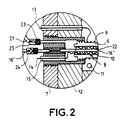
- the enclosure 7 is fitted with watertight bushings 15 allowing the electrical supply of the electrodes and of the device of heating. We can refer for better understanding in Figure 2 which represents a detail of the air supply and power supply to electrodes.
- the wall of the enclosure 7 and the sealed passages 15 remain at ambient temperatures: the problems of mechanical strength and sealing are reduced.
- the pressure at cathode 10 is more lower than the pressure at the anode 11.
- Electrodes 10, 11 are cylindrical and that they work in compression, it is not necessary to support them mechanically to ensure mechanical strength.
- the voltage across the electrodes may be typically a few volts. It is equal to the sum of the bias voltage of the electrodes, the voltage due to the electrical resistance of the membrane and of the tension due to the pressure difference of on either side of the membrane. This last tension is insignificant.
- electrodes of the same name can be connected in series to present a higher supply voltage at generator input.
- An extraction circuit 17 opening into the enclosure 7 outside the tubular membranes allows extract pressurized oxygen from the generator. This extraction circuit 17 is connected to the user device 3.
- This exhaust circuit 21 may include a common circuit and ramifications leading to proximity to membranes. We could consider reverse the air intake and exhaust circuits.
- the evacuation circuit 21 would have its ramifications inserted at the bottom of the membranes 6.
- the supply circuit of air 16 would emerge into the enclosure on the side of the cathode 10, opposite the bottom of the membranes. It would be even possible to mix the two variants.
- the fan, the arrangement of the air supply circuit 16 and the exhaust air circuit 21, allow to have a good renewal of oxygen-rich air and good evacuation of depleted air.
- the circuit conveying the air (16, 21) which enters the bottom of the membranes is provided at its ramifications a mechanical device 22 ensuring a large number of electrical contacts between the cathode 10 and the ramifications.
- a mechanical device 22 ensuring a large number of electrical contacts between the cathode 10 and the ramifications.
- FIGs 1 and 2 it is a wire conductor folded in a zigzag.
- the ramifications are made of an electrically conductive material. We can use an alloy of type NC19FeNb known as the Inconel brand.
- This mechanical device 22 associated with the porous conductive coating 8 ensures a good distribution of the electrical intensity on the cathode 10. It is advantageous to increase this electrical intensity per unit area as much as possible, since the oxygen flow rate per unit area of the generator is directly proportional to the intensity. There is however a limit not to be exceeded if one does not want to destroy the material of the membrane. For zirconia, this intensity is of the order of 1A / cm 2 and corresponds to a gas flow rate of 0.2 l / h.cm 2 under normal conditions of temperature and pressure.
- Filters 23 are provided in the supply circuits air 16, exhaust 21 and extraction 17. These filters 23 are arranged on either side of the membranes 6 preferably outside the enclosure. These filters 23 will advantageously be made of sintered bronze. Sure Figures 1 and 2, there is shown a filter 23 by branching of the air supply circuit 16 and by branching the exhaust circuit 21, there could be fewer.
- these filters 23 prevent membrane debris from polluting gases injected and extracted from the generator. Debris can be a cause of ignition and a cause of dysfunction other possible organs placed on these conduits such as valves, valves, taps ...
- non-return valves 24 are also provision on the air supply circuit 16 to branch level 16 '', non-return valves 24. They only let the gas flow go in one direction, from the outside of the enclosure to the inside. These valves 24 prevent, in the event of a rupture of a membrane 6, that a flow of hot oxygen does not escape from the compressor 5 by the air supply circuit 16.
- a flow limiter 25 On the air evacuation circuit 21 depleted, downstream of the membranes, we will place at least a flow limiter 25.
- This flow limiter 25 allows pass a flow of gas (depleted air) in operation normal. When the pressure upstream of the flow 25 is greater than a threshold, it prevents passage of the gas flow.
- a flow limiter by branching the exhaust circuit.
- These flow limiters 25 prevent an escape hot oxygen through the exhaust circuit 21 in case of rupture of a membrane 6. The confinement of high pressure hot oxygen is ensured.
- These valves check valve 24 and these flow limiters 25 can have an inconel body and a sapphire shutter.
- Exhausted oxygen-depleted air can be recovered and used to make atmospheres inert explosives for example.
- This oxygen-depleted air is rich in nitrogen.
- a recovery tank 28 at the end of the evacuation circuit 21.
- the electrochemical generator 5 has a flow allowing use oxygen during proper functioning tests respiratory equipment. We don't draw anymore in pressurized oxygen cylinders 1.
- the flow generator also provides enough oxygen to supply respiratory equipment 3 intended for at least some of the crew members, especially when the flight conditions require the wearing of a respiratory mask by at least one part of the crew.
- the electrochemical generator 5 can reinflate.
- the extraction circuit 17 communicates with pressurized oxygen cylinders 1 per through a non-return valve 29.
- the two valves 4 are in the open position.
- Means (not shown) are provided to neutralize the equipment respiratory.
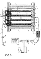
- Figure 3 shows a variant of an installation according to the invention.
- the second source of oxygen is now a chemical oxygen generator and carries the reference 30. It is connected to respiratory equipment 3 as in figure 1.
- the downstream valve 31 is closed when it is desired to maintain buffer capacity 26 under pressure. This ability buffer can also be used when the source of breathing gas is formed from pressurized bottles.
- the electrochemical generator delivers continuously in the buffer capacity as soon as enough energy is available in the aircraft, i.e. typically as soon as the auxiliary power unit is triggered.
- a radiator 27 for cooling the oxygen which leaves of the electrochemical generator 5. This may be the case when the length of the extraction circuit between the generator and the user device does not allow oxygen to cool down enough.
- the electrochemical generator supplies now in oxygen a cooler 40 of Joule-Thomson type intended to cool for example a infrared detector 41.
- the other elements of the figure located upstream of the cooler 40 are identical to those of figure 3.
- Oxygen under pressure circulates in a coil 42 placed in a cryostat 43. It holds at the lower end of the coil producing cold.
- the generator electrochemical 5 supplies oxygen to several devices users by combining for example Figures 3 and 4. Other types of user devices may of course be connected to the electrochemical generator 5.
- This generator has no moving parts, it has great reliability, it does not require no maintenance and does not generate pollution oxygen because it does not use lubricant.
Landscapes
- Chemical & Material Sciences (AREA)
- Organic Chemistry (AREA)
- Health & Medical Sciences (AREA)
- Inorganic Chemistry (AREA)
- Emergency Management (AREA)
- Business, Economics & Management (AREA)
- General Health & Medical Sciences (AREA)
- Pulmonology (AREA)
- Separation Using Semi-Permeable Membranes (AREA)
- Telephone Function (AREA)
- Air Bags (AREA)
- Packages (AREA)
- Oxygen, Ozone, And Oxides In General (AREA)
- Fittings On The Vehicle Exterior For Carrying Loads, And Devices For Holding Or Mounting Articles (AREA)
Claims (15)
- Anlage zur Versorgung mindestens einer Verbrauchervorrichtung (3) auf einem Fahrzeug mit Sauerstoff, wobei die Anlage einen an die Verbrauchervorrichtung angeschlossenen elektrochemischen Sauerstoffgenerator (5) enthält, der Sauerstoff aus der Luft entnimmt und in einen dichten und beheizten Behälter (7) eine Mehrzahl von für Sauerstoff durchlässigen rohrförmigen Membranen (6), nämlich zwei Elektroden (9, 10) je Membran, eine (10) innerhalb und eine (9) außerhalb, und eine Luftzufuhrleitung (16), eine Sauerstoff-Extraktionsleitung (17) und eine Abfuhrleitung (21) für sauerstoffarme Luft aufweist, die in den Behälter (7) münden, dadurch gekennzeichnet, daß durch die Luftzufuhrleitung (16) Umgebungsluft in die rohrförmigen und mit einem Boden versehenen Membrane (6) eingespeist wird, daß die Sauerstoff-Extraktionsleitung (17), die den Sauerstoff unter Druck entnehmen soll, in den Behälter außerhalb der Membranen (6) mündet, daß die Abfuhrleitung (21) für sauerstoffarme Luft in den Behälter (7) an der Innenseite der Membrane (6) mündet,
und daß die Luftzufuhrleitung (16) mindestens eine elektrischen Strom leitende Leitung (16") besitzt, die am Boden einer Membran mündet, wobei eine mechanische Vorrichtung (22) um die Leitung (16") herum vorgesehen ist, um eine große Zah1 von elektrischen Kontakten zwischen der Leitung (16") und der Elektrode (10) in der Membran zu gewährleisten. - Anlage nach Anspruch 1, dadurch gekennzeichnet, daß die Verbrauchervorrichtung (3) mindestens eine Atemschutzeinrichtung enthält, die an eine zweite Sauerstoffquelle (1) angeschlossen ist.
- Anlage nach einem der Ansprüche 1 oder 2, dadurch gekennzeichnet, daß die Verbrauchereinrichtung ein Kühler vom Typ Joule-Thomson (40) ist.
- Anlage nach einem der Ansprüche 1 bis 2, dadurch gekennzeichnet, daß der elektrochemische Generator (5) einen Durchsatz besitzt, der es erlaubt, Sauerstoff zum Testen der Atemschutzeinrichtungen (3) zu liefern.
- Anlage nach einem der Ansprüche 1 bis 4, dadurch gekennzeichnet, daß der elektrochemische Generator (5) einen Durchsatz besitzt, der es erlaubt, Sauerstoff zum Atmen für mindestens einen Teil der Besatzung des Fahrzeugs zu liefern.
- Anlage nach einem der Ansprüche 1 bis 5, dadurch gekennzeichnet, daß die Luftzufuhrleitung (16) mindestens eine Rückschlagklappe (24) aufweist, um im Fall des Bruchs einer Membran (6) den Sauerstoff einzuschließen.
- Anlage nach einem der Ansprüche 1 bis 6, dadurch gekennzeichnet, daß die Abfuhrleitung (21) für sauerstoffarme Luft mindestens einen Durchflußbegrenzer (25) enthält, um Sauerstoff im Fall des Bruchs einer Membran (6) einzuschließen.
- Anlage nach Anspruch 7, dadurch gekennzeichnet, daß die sauerstoffarme Luft in einem Sammelbehälter (28) gespeichert wird.
- Anlage nach einem der Ansprüche 1 bis 8, dadurch gekennzeichnet, daß ein Ventilator (20) in der Luftzufuhrleitung (16) liegt, um einen guten Luftumlauf in der Nähe der inneren Elektrode (10) zu gewährleisten.
- Anlage nach einem der Ansprüche 1 bis 9, dadurch gekennzeichnet, daß die Luftzufuhrleitung, die Sauerstoff-Extraktionsleitung und die Abfuhrleitung für sauerstoffarme Luft mit Filtern (23) versehen sind, um eventuelle Bruchstücke einer Membran zurückzuhalten.
- Anlage nach einem der Ansprüche 1 bis 10, dadurch gekennzeichnet, daß ein Pufferreservoir (26) mit einem ausgangsseitigen Ventil (31) an die Extraktionsleitung (17) angeschlossen ist, um den Sauerstoff unter Druck zu speichern, wenn der Verbrauch in der Verbrauchervorrichtung (3) Null ist.
- Anlage nach einem der Ansprüche 1 bis 11, dadurch gekennzeichnet, daß eine Kühlvorrichtung (27) in der Sauerstoff-Extraktionsleitung (17) vorgesehen ist.
- Anlage nach einem der Ansprüche 2 bis 12, dadurch gekennzeichnet, daß die zweite Sauerstoffquelle (1) eine Reserve für Sauerstoff unter Druck ist.
- Anlage nach Anspruch 13, dadurch gekennzeichnet, daß der elektrochemische Generator (5) an die Reserve für Sauerstoff unter Druck (1) angeschlossen ist, um sie mit Sauerstoff wieder aufzufüllen.
- Anlage nach einem der Ansprüche 2 bis 12, dadurch gekennzeichnet, daß die zweite Sauerstoffquelle ein elektrochemischer Sauerstoffgenerator (30) ist.
Applications Claiming Priority (2)
| Application Number | Priority Date | Filing Date | Title |
|---|---|---|---|
| FR9215905A FR2699912B1 (fr) | 1992-12-30 | 1992-12-30 | Installation d'alimentation en oxygène embarquée sur véhicule. |
| FR9215905 | 1992-12-30 |
Publications (3)
| Publication Number | Publication Date |
|---|---|
| EP0605296A1 EP0605296A1 (de) | 1994-07-06 |
| EP0605296B1 EP0605296B1 (de) | 1997-03-19 |
| EP0605296B2 true EP0605296B2 (de) | 2004-11-10 |
Family
ID=9437267
Family Applications (1)
| Application Number | Title | Priority Date | Filing Date |
|---|---|---|---|
| EP93403148A Expired - Lifetime EP0605296B2 (de) | 1992-12-30 | 1993-12-23 | Sauerstoff-Versorgungseinrichtung, untergebracht im Fahrzeug |
Country Status (4)
| Country | Link |
|---|---|
| EP (1) | EP0605296B2 (de) |
| AT (1) | ATE150425T1 (de) |
| DE (1) | DE69309024T3 (de) |
| FR (1) | FR2699912B1 (de) |
Citations (1)
| Publication number | Priority date | Publication date | Assignee | Title |
|---|---|---|---|---|
| WO1991006691A1 (en) † | 1989-11-06 | 1991-05-16 | Ceramatec, Inc. | Solid state oxygen compressor |
Family Cites Families (2)
| Publication number | Priority date | Publication date | Assignee | Title |
|---|---|---|---|---|
| US5045169A (en) * | 1990-02-05 | 1991-09-03 | Westinghouse Electric Corp. | Solid oxide electrolyte electrochemical oxygen generator |
| US5169506A (en) * | 1990-12-31 | 1992-12-08 | Invacare Corporation | Oxygen concentration system utilizing pressurized air |
-
1992
- 1992-12-30 FR FR9215905A patent/FR2699912B1/fr not_active Expired - Lifetime
-
1993
- 1993-12-23 DE DE69309024T patent/DE69309024T3/de not_active Expired - Lifetime
- 1993-12-23 EP EP93403148A patent/EP0605296B2/de not_active Expired - Lifetime
- 1993-12-23 AT AT93403148T patent/ATE150425T1/de not_active IP Right Cessation
Patent Citations (1)
| Publication number | Priority date | Publication date | Assignee | Title |
|---|---|---|---|---|
| WO1991006691A1 (en) † | 1989-11-06 | 1991-05-16 | Ceramatec, Inc. | Solid state oxygen compressor |
Also Published As
| Publication number | Publication date |
|---|---|
| ATE150425T1 (de) | 1997-04-15 |
| DE69309024T2 (de) | 1997-06-19 |
| FR2699912B1 (fr) | 1995-01-27 |
| DE69309024T3 (de) | 2005-02-03 |
| EP0605296B1 (de) | 1997-03-19 |
| DE69309024D1 (de) | 1997-04-24 |
| FR2699912A1 (fr) | 1994-07-01 |
| EP0605296A1 (de) | 1994-07-06 |
Similar Documents
| Publication | Publication Date | Title |
|---|---|---|
| EP3494608B1 (de) | Regelkreis zur steuerung der temperatur und des drucks eines hochtemperatur-elektolyseurs (soec), der reversibel als brennstoffzelle (sofc) betreibbar ist | |
| EP2494643B1 (de) | Verfahren zur erkennung des versiegelten zustandes einer brennstoffzelle | |
| EP2017916B1 (de) | Abschalten einer mit reinem Sauerstoff gespeisten Brennstoffzelle | |
| EP0510877A1 (de) | System zur Sauerstoffanreicherung unter Verwendung von Druckluft | |
| EP0550892A1 (de) | Kraftwerk mit Brennstoffzellen | |
| EP0153247A1 (de) | Ausrüstung zum Schutz von Personen gegen Verseuchung | |
| FR2944648A1 (fr) | Dispositif de production d'electricite pour sous-marin comportant une pile a combustible | |
| JP6494981B2 (ja) | 固体酸化物形燃料電池システム及びこれを備える複合発電システム、並びに、固体酸化物形燃料電池システムの停止方法 | |
| EP2494644A1 (de) | Verfahren zur erkennung des permeabilitätszustandes der ionenaustauschpolymermembran einer brennstoffzelle | |
| EP0605296B2 (de) | Sauerstoff-Versorgungseinrichtung, untergebracht im Fahrzeug | |
| EP4298684A1 (de) | Vorrichtung zur versorgung einer vielzahl von kathoden eines brennstoffzellensystems | |
| CA3066843A1 (fr) | Systeme d'inertage d'au moins un volume dans un aeronef via au moins une pile a combustible | |
| CA3008699A1 (fr) | Dispositif electrochimique a conduction protonique avec reformage integre et procede de fabrication associe | |
| US20140076736A1 (en) | High purity ceramic oxygen generator | |
| ES2357407T3 (es) | Integración de electrodo pasivo en una pila de combustible. | |
| KR100487667B1 (ko) | 연료전지시스템 | |
| EP1207579A2 (de) | Verfahren und Vorrichtung zur Sicherung des Startens einer Brennstoffzelle | |
| EP1657770B1 (de) | Verfahren zur Versorgung einer Brennstoffzellenkathode mit einem Sauerstoff enthaltenden Gas und Brennstoffzelle damit | |
| JPH09180747A (ja) | 電源装置 | |
| WO2025051771A1 (fr) | Pile à combustible et procédé de pilotage associé | |
| FR2788169A1 (fr) | Procede d'alimentation en gaz reactif, de pile a combustible , et dispositif de mise en oeuvre de ce procede | |
| FR2601821A1 (fr) | Dispositif de controle de niveau centralise pour batteries d'accumulateurs electriques | |
| FR2868213A1 (fr) | Dispositif de gestion des gaz d'un systeme pile a combustible | |
| WO2017089679A1 (fr) | Systeme de generation d'energie destine a etre monte dans un aeronef. | |
| WO2022136315A1 (fr) | Dispositif de purge de compartiment anodique d'une pile à combustible |
Legal Events
| Date | Code | Title | Description |
|---|---|---|---|
| PUAI | Public reference made under article 153(3) epc to a published international application that has entered the european phase |
Free format text: ORIGINAL CODE: 0009012 |
|
| AK | Designated contracting states |
Kind code of ref document: A1 Designated state(s): AT BE CH DE DK ES FR GB GR IE IT LI LU MC NL PT SE |
|
| 17P | Request for examination filed |
Effective date: 19940816 |
|
| 17Q | First examination report despatched |
Effective date: 19950825 |
|
| GRAG | Despatch of communication of intention to grant |
Free format text: ORIGINAL CODE: EPIDOS AGRA |
|
| GRAH | Despatch of communication of intention to grant a patent |
Free format text: ORIGINAL CODE: EPIDOS IGRA |
|
| GRAH | Despatch of communication of intention to grant a patent |
Free format text: ORIGINAL CODE: EPIDOS IGRA |
|
| GRAA | (expected) grant |
Free format text: ORIGINAL CODE: 0009210 |
|
| AK | Designated contracting states |
Kind code of ref document: B1 Designated state(s): AT BE CH DE DK ES FR GB GR IE IT LI LU MC NL PT SE |
|
| PG25 | Lapsed in a contracting state [announced via postgrant information from national office to epo] |
Ref country code: NL Free format text: LAPSE BECAUSE OF FAILURE TO SUBMIT A TRANSLATION OF THE DESCRIPTION OR TO PAY THE FEE WITHIN THE PRESCRIBED TIME-LIMIT Effective date: 19970319 Ref country code: IT Free format text: LAPSE BECAUSE OF FAILURE TO SUBMIT A TRANSLATION OF THE DESCRIPTION OR TO PAY THE FEE WITHIN THE PRESCRIBED TIME-LIMIT;WARNING: LAPSES OF ITALIAN PATENTS WITH EFFECTIVE DATE BEFORE 2007 MAY HAVE OCCURRED AT ANY TIME BEFORE 2007. THE CORRECT EFFECTIVE DATE MAY BE DIFFERENT FROM THE ONE RECORDED. Effective date: 19970319 Ref country code: GR Free format text: LAPSE BECAUSE OF FAILURE TO SUBMIT A TRANSLATION OF THE DESCRIPTION OR TO PAY THE FEE WITHIN THE PRESCRIBED TIME-LIMIT Effective date: 19970319 Ref country code: ES Free format text: THE PATENT HAS BEEN ANNULLED BY A DECISION OF A NATIONAL AUTHORITY Effective date: 19970319 Ref country code: DK Effective date: 19970319 Ref country code: AT Effective date: 19970319 |
|
| REF | Corresponds to: |
Ref document number: 150425 Country of ref document: AT Date of ref document: 19970415 Kind code of ref document: T |
|
| REG | Reference to a national code |
Ref country code: CH Ref legal event code: EP |
|
| REF | Corresponds to: |
Ref document number: 69309024 Country of ref document: DE Date of ref document: 19970424 |
|
| REG | Reference to a national code |
Ref country code: IE Ref legal event code: FG4D Free format text: 72570 |
|
| GBT | Gb: translation of ep patent filed (gb section 77(6)(a)/1977) |
Effective date: 19970522 |
|
| PG25 | Lapsed in a contracting state [announced via postgrant information from national office to epo] |
Ref country code: SE Effective date: 19970619 Ref country code: PT Effective date: 19970619 |
|
| NLV1 | Nl: lapsed or annulled due to failure to fulfill the requirements of art. 29p and 29m of the patents act | ||
| PLBQ | Unpublished change to opponent data |
Free format text: ORIGINAL CODE: EPIDOS OPPO |
|
| PLBI | Opposition filed |
Free format text: ORIGINAL CODE: 0009260 |
|
| PG25 | Lapsed in a contracting state [announced via postgrant information from national office to epo] |
Ref country code: LU Free format text: LAPSE BECAUSE OF NON-PAYMENT OF DUE FEES Effective date: 19971223 |
|
| PG25 | Lapsed in a contracting state [announced via postgrant information from national office to epo] |
Ref country code: LI Free format text: LAPSE BECAUSE OF NON-PAYMENT OF DUE FEES Effective date: 19971231 Ref country code: CH Free format text: LAPSE BECAUSE OF NON-PAYMENT OF DUE FEES Effective date: 19971231 Ref country code: BE Free format text: LAPSE BECAUSE OF NON-PAYMENT OF DUE FEES Effective date: 19971231 |
|
| PLBF | Reply of patent proprietor to notice(s) of opposition |
Free format text: ORIGINAL CODE: EPIDOS OBSO |
|
| 26 | Opposition filed |
Opponent name: L'AIR LIQUIDE, SOCIETE ANONYME POUR L'ETUDE ET L'E Effective date: 19971212 |
|
| PG25 | Lapsed in a contracting state [announced via postgrant information from national office to epo] |
Ref country code: IE Free format text: LAPSE BECAUSE OF NON-PAYMENT OF DUE FEES Effective date: 19980330 |
|
| REG | Reference to a national code |
Ref country code: IE Ref legal event code: FD4D Ref document number: 72570 Country of ref document: IE |
|
| PLBF | Reply of patent proprietor to notice(s) of opposition |
Free format text: ORIGINAL CODE: EPIDOS OBSO |
|
| BERE | Be: lapsed |
Owner name: CRYOTECHNOLOGIES Effective date: 19971231 |
|
| PG25 | Lapsed in a contracting state [announced via postgrant information from national office to epo] |
Ref country code: MC Free format text: LAPSE BECAUSE OF NON-PAYMENT OF DUE FEES Effective date: 19980630 |
|
| REG | Reference to a national code |
Ref country code: CH Ref legal event code: PL |
|
| REG | Reference to a national code |
Ref country code: GB Ref legal event code: IF02 |
|
| PLAW | Interlocutory decision in opposition |
Free format text: ORIGINAL CODE: EPIDOS IDOP |
|
| PUAH | Patent maintained in amended form |
Free format text: ORIGINAL CODE: 0009272 |
|
| STAA | Information on the status of an ep patent application or granted ep patent |
Free format text: STATUS: PATENT MAINTAINED AS AMENDED |
|
| 27A | Patent maintained in amended form |
Effective date: 20041110 |
|
| AK | Designated contracting states |
Kind code of ref document: B2 Designated state(s): AT BE CH DE DK ES FR GB GR IE IT LI LU MC NL PT SE |
|
| REG | Reference to a national code |
Ref country code: ES Ref legal event code: FD2A Effective date: 19971224 |
|
| GBTA | Gb: translation of amended ep patent filed (gb section 77(6)(b)/1977) | ||
| PGFP | Annual fee paid to national office [announced via postgrant information from national office to epo] |
Ref country code: GB Payment date: 20121219 Year of fee payment: 20 |
|
| PGFP | Annual fee paid to national office [announced via postgrant information from national office to epo] |
Ref country code: FR Payment date: 20130107 Year of fee payment: 20 |
|
| PGFP | Annual fee paid to national office [announced via postgrant information from national office to epo] |
Ref country code: DE Payment date: 20121219 Year of fee payment: 20 |
|
| REG | Reference to a national code |
Ref country code: DE Ref legal event code: R071 Ref document number: 69309024 Country of ref document: DE |
|
| REG | Reference to a national code |
Ref country code: DE Ref legal event code: R071 Ref document number: 69309024 Country of ref document: DE |
|
| REG | Reference to a national code |
Ref country code: GB Ref legal event code: PE20 Expiry date: 20131222 |
|
| PG25 | Lapsed in a contracting state [announced via postgrant information from national office to epo] |
Ref country code: GB Free format text: LAPSE BECAUSE OF EXPIRATION OF PROTECTION Effective date: 20131222 Ref country code: DE Free format text: LAPSE BECAUSE OF EXPIRATION OF PROTECTION Effective date: 20131224 |