EP0604614B1 - Dispenser with reservoir actuation - Google Patents
Dispenser with reservoir actuation Download PDFInfo
- Publication number
- EP0604614B1 EP0604614B1 EP93914571A EP93914571A EP0604614B1 EP 0604614 B1 EP0604614 B1 EP 0604614B1 EP 93914571 A EP93914571 A EP 93914571A EP 93914571 A EP93914571 A EP 93914571A EP 0604614 B1 EP0604614 B1 EP 0604614B1
- Authority
- EP
- European Patent Office
- Prior art keywords
- dispenser
- liquid
- reservoir
- container
- level
- Prior art date
- Legal status (The legal status is an assumption and is not a legal conclusion. Google has not performed a legal analysis and makes no representation as to the accuracy of the status listed.)
- Expired - Lifetime
Links
Images


Classifications
-
- A—HUMAN NECESSITIES
- A47—FURNITURE; DOMESTIC ARTICLES OR APPLIANCES; COFFEE MILLS; SPICE MILLS; SUCTION CLEANERS IN GENERAL
- A47K—SANITARY EQUIPMENT; ACCESSORIES THEREFOR, e.g. TOILET ACCESSORIES
- A47K5/00—Holders or dispensers for soap, toothpaste or the like
- A47K5/06—Dispensers for soap
- A47K5/12—Dispensers for soap for liquid or pasty soap
- A47K5/1211—Dispensers for soap for liquid or pasty soap using pressure on soap, e.g. with piston
Definitions
- This invention relates to dispensers for liquids the dispensers being operable manually or by a suitable actuator to create an increase of pressure in the dispenser which in turn results in dispensing.
- Products in liquid form have for many years been packaged in a variety of containers suitable for shipping, displaying, handling and eventual sale. These containers have been made in a great variety of shapes and sizes with different types of closures. They include glass containers, and containers of synthetic plastics materials which have been molded, blow-molded and generally formed into shape. Also, because of the nature of these plastics materials, the closures can be of many various types including screw caps, flip tops, and simple bonded seals. In general, containers of these types have been made to enhance the product and little thought was given to disposing of the container.
- the present dispenser fits into this arrangement and can be adapted to dispense liquid from bulk containers.
- Dispensers according to the invention have advantages when used in this way also.
- Dispensers of the present type are taught by U.S. Patents Serial Nos. 4,324,349, 4,635,828, 4,645,097, and 5,033,653. These dispensers have no moving parts and yet satisfy the requirements of clean dispensing with temperature compensation to permit the dispenser to be subjected to a designed temperature range without inadvertent dripping or dispensing caused by temperature variations.
- the dispensers have a reservoir containing some of the liquid to be dispensed and in communication with the main part of the dispenser in the form of a container where the major volume of the liquid is contained. Air is trapped above the liquid in the container under a negative pressure which prevents the liquid flowing through the reservoir and out through a discharge passageway. When the container is deformed, the negative pressure is overcome to some extent so that liquid will flow out of the container and into the reservoir, then out via the passageway. As soon as the pressure is released, a negative pressure is created by the walls of the container returning from a deflected condition to the original condition so that air is sucked back into the passageway and the reservoir is set up in a condition of equilibrium.
- U.S. Patent No. 5,033,653 is an improvement over the earlier patents in which the concept of temperature fluctuation is separated as a parameter frog response rate. This is achieved by providing a small opening communicating the reservoir to atmosphere so that as temperature compensation takes place equalization will result through the small opening. On the other hand, when dispensing takes place the opening is too small to allow sudden passage of air so that the flow of liquid will take place almost entirely through the passageway with the result that the response is essentially immediate.
- the invention concerns a dispenser for liquids of the type having a container for storing the liquid at a first level, and a reservoir below said first level providing liquid communication with the container so that some liquid at a second level in the reservoir traps liquid in the container due to the buildup of a negative pressure on the container above the first level of liquid, and an outlet passageway extending upwardly from about said second level and terminating outside the dispenser, and displacement structure to cause liquid to dispense through the outlet passageway, the dispenser being characterized in that the container is rigid and the displacement structure is operable to increase the pressure in the reservoir to cause liquid to flow from the reservoir through the outlet passageway.
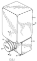
- Fig. 1 illustrates a preferred embodiment of dispenser for wall mounting and manual operation.
- the dispenser is indicated generally by the numeral 20 and includes a container 22 which holds a main portion of the liquid to be dispensed, and a reservoir 24 which normally contains a smaller portion of the liquid as it travels from the container to an outlet 26.
- the dispenser is operated by the user pressing on an end 28 of a bellows 30 forming a resiliently deformable part of the reservoir 24.
- Figs. 1 and 2 are a sectional view of Fig. 1.
- the container 22 defines a downwardly extending neck 32 terminating at an open end or outlet 34.
- the reservoir 24 defines an opening 36 which fits closely about the neck 32 and is sealed in place. The proportions of the reservoir are such that the outlet 34 is towards the bottom of the reservoir and as will be explained, it is normally surrounded by the reservoir and by a smaller portion 38 of the liquid in the dispenser.
- the neck 32 contains an insert designated generally by the numeral 40 which defines with the neck an outlet passageway 41 extending upwardly to meet the outlet 26 and to provide an outlet path for liquid from the dispenser.
- a closed cylindrical portion 42 extends upwardly from a radial boss 44 shaped to fit into the end of the neck 32.
- the boss defines a plurality of holes 46 to provide communication for liquid from the container 22 into the reservoir 24.
- the outlet passageway commences upwardly from adjacent the neck outlet inside the cylindrical portion 42 and outside the tubular outlet 26.
- the cylindrical portion 42 is spaced from the outlet 26 to permit flow upwardly between these parts and then into the outlet 26 which extends through a suitable opening formed in the reservoir.
- the reservoir 24 is also in communication with atmosphere via a small hole 47 in the wall of the reservoir. This small hole allows the space in the reservoir to receive liquid if the temperature increases because air will be displaced through its hole. However when the bellows 30 is deformed the hole is too small to permit significant air flow so that the reservoir is in effect closed above the smaller portion 38 of the liquid.
- the rigidity of the container 22 should be chosen to maintain its shape under the influence of a negative pressure within the container. Also, because the pressure within the reservoir is atmospheric, the bellows 24 can be of a light material but sufficiently resilient to return to its original shape after it is deformed to dispense liquid. Also, as shown in Fig. 2, depending upon the design, there may be some liquid within the bellows and the strength of the bellows would have to take this into consideration. Of course if the bellows were located higher than it is shown in Fig. 2, then the presence of liquid could be avoided.
- the dispenser when the dispenser is not in use, it may be subject to changes in ambient temperature. This will affect the negative pressure as is described in the aforementioned patents by the same applicant. An increase in temperature will result in some flow from the container to the reservoir and the liquid level in the reservoir will rise slowly. This is permitted by the very small ventilation opening 47. Similarly, if the temperature decreases, there will be a flow back into the container and again equalization is permitted above the level of liquid in the reservoir by the opening 47.
- the user When the dispenser is to be actuated, the user deforms the bellows 30 thereby reducing the volume of the reservoir 24 and creating a pressure greater than atmospheric. There will be some flow of air through the opening 47 but this will be minor due to the very small opening (provided of course that the person pushing the bellows does so normally and not extremely slowly).
- This increase in pressure will change the relationship between p, H and P but because of the minimal resistance to flow in the outlet passageway, the major change will be that the level of liquid 38 will fall as most of it is dispensed through the passageway and some of it returns to the container 22.
- the proportions of the reservoir and the bellows are chosen so that the user pressing the actuator or bellows 24 will bring the level down to somewhere near the bottom of the neck 32 but will not normally result in air being blown through the outlet passageway.
- the proportions can be chosen so that liquid will flow through the discharge passageway followed by air if the user attempts to discharge more than a predetermined volume of discharge.
- the amounts discharged over a period can vary within limits due to the changes in the relationships between small p, P and H as the level of the liquid in the container drops during dispensing but nevertheless some control can be effected.
- the dispenser shown in Fig. 1 is intended primarily to be positioned in the orientation shown in Fig. 1 so that some form of wall hanger or the like would be appropriate.
- the container 22 would be provided full of liquid and entered into the reservoir before dispensing. Alternatively, the container could be removed and refilled before being positioned in the arrangement shown in Figs. 1 and 2.
- Fig. 3 illustrates an alternative embodiment of dispenser made up of a rigid container 52 shown in part, a reservoir 54, the outlet 50, and an actuator 56.
- this reservoir arrangement would be an attachment to an existing container which could be of quite large volume. The limitation is not in the volume itself but in the height indicated by H in Fig. 2. Clearly a very large value for this variable would result in a large negative pressure and would have an effect on how the system operates. By contrast, if the container is wide rather than high, then the static fluid pressures in the system would be like those shown in Fig. 2. All of this has to be taken into consideration in designing the size of the reservoir and in particular the height of the reservoir to ensure proper dispensing without inadvertent discharge.
- the container 52 has a threaded neck 58 to which is attached the reservoir 54 by means of an internally threaded boss 60 which seals on the neck 58.
- a cylindrical skirt 62 extends downwardly from the boss inside the reservoir to effectively extend the neck to a point adjacent the bottom of the reservoir. This skirt is surrounded by liquid 64 forming a smaller portion of the liquid similar to portion 38 described with reference to Fig. 2.
- the equilibrium is set up by creating a negative pressure in the container 52 while there is an atmospheric pressure above the liquid 64 in the reservoir 54.
- the outlet 50 defines an outlet passageway and extends from an inlet 66 to an exit 68. As shown, the inlet 66 is below the level of the lower extremity of the skirt 62 so that in effect the opening to the container 52 lies at about the same level as the inlet 66. The relationship between these parts will become more apparent with reference to further description.
- the actuator 56 can take any convenient form. For instance a small air pump operated by a switch 70 would create a positive pressure in the reservoir and cause the level of the liquid to fall as liquid both moves back into the container 52 and also dispenses through the outlet passageway in the outlet 50. If the actuator 56 continues to provide pressure inside the reservoir, then the level around the skirt 62 will drop to the point where air will start to flow around the skirt and upwardly into the container to displace further liquid which will fall into the reservoir. If the entry to the outlet 50 is sufficiently low, then liquid will continue to flow regardless of the fact that there is an interchange of air and liquid in the container 22. On the other hand, if it is desired to limit the flow through the outlet 50, then by raising the inlet 66 appropriately, a discharge of liquid will take place followed by a flow of air.
- a ventilation opening 72 which like the opening 47 in Fig. 2 is a very small opening to permit temperature compensation within the reservoir while at the same time being sufficiently small that there is no significant flow through the opening when dispensing takes place.
- the actuator 56 can take many forms.
- a plunger arrangement could be used somewhat like a syringe so that although there is displacement and the volume in the reservoir is effectively reduced, there is no flow of ambient air into the reservoir. This may be desirable in circumstances where the air may not be clean.
- a balloon could be used. This could be inflated and would again effectively reduce the volume in the reservoir and cause dispensing. All of these possibilities are within the scope of the word "actuator" as used in this specification.
- a rigid container is designated generally by the numeral 74 and contains a reservoir 76 and outlet 78.
- the reservoir 76 and outlet 78 are of unitary construction and separated by an intermediate wall 80.
- At the top of the reservoir there is an inlet tube 82 having a very small opening 84 similar to openings 47 and 72 described with reference to drawings 2 and 3 respectively.
- the outlet 78 terminates at an exit 86 and the reservoir structure is completed by a plate 88 which is a snap fit in a suitable opening formed in the wall of the container 74. The fit is of course a seal also.
- Liquid 90 to be dispensed is contained within the reservoir by a negative pressure "P" as previously described.
- the reservoir and outlet are at atmospheric pressure and the level of liquid in these parts is indicated by the numeral 92.
- the dispenser 74 can be actuated by an actuator 94 which is operated to create a pressure within the reservoir 76 in the manner described with reference to the actuator 56 described with reference to Fig. 3.
- the outlet 78 has an entrance 95 below an entrance 96 to the reservoir 76. As discussed previously, this relationship ensures that the outlet will continue to dispense while air is finding its way to the top of the container to displace more liquid from the container.
- Fig. 4 is of interest because the structure used to dispense is essentially added to the container but, unlike the containers described previously, there is no neck.
- the container would be filled through the opening provided for the plate 88 and then the structure snapped in place before placing the container in the position shown in Fig. 4.
- the container will be essentially rigid and could be a glass bottle or any other structure already in use in the market place. Structure including the reservoir and associated parts can be added to the existing bottle to eke a dispenser with the bottle hanging upside down.
- the dispensers described can take many forms for various uses.
- the bottom discharge type shown in the exemplary embodiment seen in Fig. 1 can be used to dispense product such as liquid soap onto a user's hand from a wall-mounted location.
- Other applications would include remote dispensing using an actuator and switch such as that seen in Fig. 3 or, in a different form, in Fig. 4.
- Other dispensers could be lifted and squeezed and could dispense liquid food products, soaps, shampoos and the like.
- the uses are both domestic and institutional.
Landscapes
- Health & Medical Sciences (AREA)
- Public Health (AREA)
- Containers And Packaging Bodies Having A Special Means To Remove Contents (AREA)
- Closures For Containers (AREA)
- Devices For Dispensing Beverages (AREA)
Description
- 20
- Dispenser
- 22
- Container
- 24
- Reservoir
- 26
- Outlet
- 28
- End of Bellows
- 30
- Bellows
- 32
- Neck
- 34
- Outlet
- 36
- Opening
- 38
- Portion of liquid
- 40
- Insert
- 41
- Outlet Passageway
- 42
- Cylindrical Portion
- 44
- Radial Boss
- 46
- Holes
- 47
- Hole
- 48
- Main Portion of Liquid
- 50
- Outlet
- 52
- Container
- 54
- Reservoir
- 56
- Actuator
- 58
- Threaded Neck
- 60
- Threaded Boss
- 62
- Cylindrical Skirt
- 64
- Liquid
- 66
- Inlet
- 68
- Exit
- 70
- Switch
- 72
- Ventilation Opening
- 74
- Container
- 76
- Reservoir
- 78
- Outlet
- 80
- Wall
- 82
- Inlet Tube
- 84
- Small Opening
- 86
- Exit
- 88
- Plate
- 90
- Liquid
- 92
- Liquid level
- 94
- Actuator
- 95
- Entrance
- 96
- Entrance
Claims (12)
- A dispenser for liquids of the type having a container (22, 52, 74) for storing the liquid at a first level, and a reservoir (24, 54, 76) below said first level providing liquid communication with the container so that some liquid at a second level in the reservoir traps liquid in the container due to the buildup of a negative pressure on the container above the first level of liquid, and an outlet passageway (41, 50, 78) extending upwardly from below said second level and terminating outside the dispenser, and displacement structure to cause liquid to dispense through the outlet passageway, the dispenser being characterized in that the container is rigid and the displacement structure is operable to increase the pressure in the reservoir to cause liquid to flow from the reservoir through the outlet passageway.
- A dispenser as claimed in claim 1 and further characterized by the container being in the form of an inverted bottle having a neck.
- A dispenser as claimed in claim 1 and further characterized by the reservoir being located inside the container.
- A dispenser as claimed in claims 1 or 2 and further characterized by an equalization opening (47) providing communication with atmosphere sufficient to permit slow equalization of pressure in the reservoir during changes in ambient temperature.
- A dispenser as claimed in claim 3 and further characterized by an equalization opening (84) providing communication with atmosphere sufficient to permit slow equalization of pressure in the reservoir during changes in ambient temperature.
- A dispenser as claimed in claims 1 or 2 and further characterized by the displacement structure including a resilient element (30) which returns to its original shape after said actuation to thereby cause a reverse flow in the outlet passageway to clean liquid from the exit after dispensing.
- A dispenser as claimed in claims 1, 2 or 3 in which the displacement structure is an actuator (94) providing a source of pressurized fluid and a switch (70) for selectively actuating the displacement structure.
- A dispenser as claimed in claims 1, 2 and 3 in which the displacement structure causes a reverse flow in the outlet passageway after dispensing to clean liquid from the exit.
- A dispenser as claimed in claim 1 and further characterized by the displacement structure containing liquid and said second level extending into the displacement structure.
- A dispenser as claimed in claim 9 and further characterized by the displacement structure being a bellows (30).
- A dispenser as claimed in claim 1 and further characterized by the outlet passageway terminating at an exit below said second level.
- A dispenser as claimed in claim 1 and further characterized by the outlet passageway terminating at an exit (68, 86) above said second level.
Applications Claiming Priority (3)
| Application Number | Priority Date | Filing Date | Title |
|---|---|---|---|
| CA002072913A CA2072913A1 (en) | 1992-07-02 | 1992-07-02 | Dispenser with reservoir actuator |
| CA2072913 | 1992-07-02 | ||
| PCT/CA1993/000258 WO1994001032A1 (en) | 1992-07-02 | 1993-07-02 | Dispenser with reservoir actuation |
Publications (2)
| Publication Number | Publication Date |
|---|---|
| EP0604614A1 EP0604614A1 (en) | 1994-07-06 |
| EP0604614B1 true EP0604614B1 (en) | 1998-04-01 |
Family
ID=4150098
Family Applications (1)
| Application Number | Title | Priority Date | Filing Date |
|---|---|---|---|
| EP93914571A Expired - Lifetime EP0604614B1 (en) | 1992-07-02 | 1993-07-02 | Dispenser with reservoir actuation |
Country Status (7)
| Country | Link |
|---|---|
| US (1) | US5427279A (en) |
| EP (1) | EP0604614B1 (en) |
| JP (1) | JPH06510219A (en) |
| AU (1) | AU4414093A (en) |
| CA (1) | CA2072913A1 (en) |
| DE (1) | DE69317747T2 (en) |
| WO (1) | WO1994001032A1 (en) |
Families Citing this family (27)
| Publication number | Priority date | Publication date | Assignee | Title |
|---|---|---|---|---|
| ATE175554T1 (en) * | 1994-11-10 | 1999-01-15 | Kaufman Products Inc | DISPENSER WITH LIQUID DISPENSE REGULATION |
| GB9513323D0 (en) * | 1995-06-30 | 1995-09-06 | Talley Group Ltd | Improvements in or relating to applied pressure indicators |
| US5984146A (en) * | 1996-09-27 | 1999-11-16 | Kaufman; John G. | Dispenser having foamed output |
| US5975364A (en) * | 1996-09-27 | 1999-11-02 | Kaufman Products Inc. | Dispenser having dual containers |
| US5803315A (en) * | 1997-01-06 | 1998-09-08 | Kaufman Products Inc. | Dispenser having removable container |
| US5894961A (en) * | 1997-01-24 | 1999-04-20 | Kaufman Products Inc. | Dispenser with resilient reservoir structure |
| US5884817A (en) * | 1997-01-30 | 1999-03-23 | Kaufman Products Inc. | Tilt dispenser |
| US5904272A (en) * | 1997-11-12 | 1999-05-18 | Kaufman Products Inc. | Dispenser for liquids |
| US5996851A (en) * | 1998-09-28 | 1999-12-07 | Gojo Industries, Inc. | Bladder-operated dispenser |
| US6401985B1 (en) * | 2000-11-27 | 2002-06-11 | Demars Robert A. | Liquid dispensing apparatus |
| US6543651B2 (en) | 2000-12-19 | 2003-04-08 | Kimberly-Clark Worldwide, Inc. | Self-contained viscous liquid dispenser |
| US6516976B2 (en) | 2000-12-19 | 2003-02-11 | Kimberly-Clark Worldwide, Inc. | Dosing pump for liquid dispensers |
| US6540117B2 (en) | 2001-03-30 | 2003-04-01 | Kimberly-Clark Worldwide, Inc. | Dosing pump for liquid dispensers |
| CA2381868C (en) * | 2002-04-16 | 2009-09-01 | Hygiene-Technik Inc. | Vacuum relief device |
| US7198175B2 (en) | 2002-04-26 | 2007-04-03 | Heiner Ophardt | Manual or pump assist fluid dispenser |
| US7556178B2 (en) * | 2002-04-26 | 2009-07-07 | Hygiene-Technik Inc. | One-way valve and vacuum relief device |
| US7815076B2 (en) * | 2002-04-26 | 2010-10-19 | Gotohti.Com Inc. | Vacuum released valve |
| US20070194053A1 (en) * | 2002-04-26 | 2007-08-23 | Heiner Ophardt | Fire resistant container system |
| US7228994B2 (en) * | 2003-08-18 | 2007-06-12 | Maytag Corporation | Delayed flow water reservoir for a clothes drying cabinet and method of use |
| ATE340324T1 (en) * | 2003-12-23 | 2006-10-15 | Techspace Aero Sa | VALVE FOR SPACE APPLICATIONS WITH SMA ACTUATOR |
| GB2417025A (en) * | 2004-08-14 | 2006-02-15 | Ebac Ltd | Flow assembly for a bottled liquid dispenser |
| CA2667103C (en) * | 2008-05-28 | 2016-09-06 | Gojo Industries, Inc. | Air piston and dome foam pump |
| US8616414B2 (en) * | 2009-02-09 | 2013-12-31 | Gojo Industries, Inc. | Bellows foam dispenser |
| US8308027B2 (en) | 2009-12-01 | 2012-11-13 | Regent Medical Center | Automatic soap dispenser with top-side motor and methods |
| ITRM20120163A1 (en) * | 2012-04-17 | 2013-10-18 | Ennio Cardia | DEVICE FOR CONTROLLED DISPENSING OF FLUIDS. |
| CA2882828A1 (en) * | 2015-02-24 | 2016-08-24 | Op-Hygiene Ip Gmbh | Liquid dispenser with removable mobile dispenser |
| WO2017125519A1 (en) * | 2016-01-19 | 2017-07-27 | Obrist Closures Switzerland Gmbh | Dosing device |
Family Cites Families (17)
| Publication number | Priority date | Publication date | Assignee | Title |
|---|---|---|---|---|
| DE241635C (en) * | ||||
| US2609971A (en) * | 1950-07-24 | 1952-09-09 | Michael D Vivolo | Salt dispenser |
| AT227885B (en) * | 1961-10-12 | 1963-06-10 | Photo Entwicklungsgeraete Ag | Device for dispensing a slightly dripping liquid |
| FR2272902A2 (en) * | 1974-05-30 | 1975-12-26 | Delmas Albert | Wall mounted liquid soap dispenser - has flexible bellows on front face to be pressed by knuckles |
| IT1022669B (en) * | 1974-10-07 | 1978-04-20 | Macchi Cassia Antonio | PARTICULARLY DISTRIBUTOR FOR LIQUID SOAP |
| DE2728683A1 (en) * | 1977-06-25 | 1979-01-11 | Wella Ag | DEVICE FOR FOAMING OR SPRAYING LIQUIDS |
| US4324349A (en) * | 1980-01-14 | 1982-04-13 | Kaufman John George | Container for dispensing liquid |
| US4645097A (en) * | 1983-04-07 | 1987-02-24 | Kaufman John George | Sidewall dispenser |
| US4635828A (en) * | 1984-06-27 | 1987-01-13 | Kaufman John George | Liquid container dispensing cap structure |
| DE3812935A1 (en) * | 1988-04-19 | 1989-11-02 | Oeco Tech Entwicklung & Vertri | AUTOMATIC SPRAY CAN |
| US4917265A (en) * | 1988-05-04 | 1990-04-17 | Chiang Meng C | Automatic liquid dispenser |
| CA1340153C (en) * | 1988-06-21 | 1998-12-01 | John G. Kaufman | Dispenser with compression chamber |
| US4966312A (en) * | 1988-12-06 | 1990-10-30 | Waring Donald A | Disposable oral liquid measure dispenser |
| DE3902476A1 (en) * | 1989-01-27 | 1990-08-02 | Feldmuehle Ag | DISPENSING DEVICE FOR LIQUID OR PASTOESE GOETER |
| US5060830A (en) * | 1989-02-02 | 1991-10-29 | Owens-Illinois Plastic Products Inc. | Dispensing package for dispensing liquids |
| FR2653762A1 (en) * | 1989-10-30 | 1991-05-03 | France Assessoires Automobiles | Manual dispenser mixer for products composed of a mixture |
| CA2062557A1 (en) * | 1992-03-09 | 1993-09-10 | John G. Kaufman | Liquid dispenser |
-
1992
- 1992-07-02 CA CA002072913A patent/CA2072913A1/en not_active Abandoned
-
1993
- 1993-07-02 WO PCT/CA1993/000258 patent/WO1994001032A1/en not_active Ceased
- 1993-07-02 AU AU44140/93A patent/AU4414093A/en not_active Abandoned
- 1993-07-02 EP EP93914571A patent/EP0604614B1/en not_active Expired - Lifetime
- 1993-07-02 JP JP6502787A patent/JPH06510219A/en active Pending
- 1993-07-02 DE DE69317747T patent/DE69317747T2/en not_active Expired - Fee Related
- 1993-07-02 US US08/204,194 patent/US5427279A/en not_active Expired - Fee Related
Also Published As
| Publication number | Publication date |
|---|---|
| DE69317747T2 (en) | 1998-11-12 |
| DE69317747D1 (en) | 1998-05-07 |
| WO1994001032A1 (en) | 1994-01-20 |
| JPH06510219A (en) | 1994-11-17 |
| CA2072913A1 (en) | 1994-01-03 |
| US5427279A (en) | 1995-06-27 |
| AU4414093A (en) | 1994-01-31 |
| EP0604614A1 (en) | 1994-07-06 |
Similar Documents
| Publication | Publication Date | Title |
|---|---|---|
| US5427279A (en) | Dispenser with reservoir actuation | |
| US5033653A (en) | Dispenser with compression chamber | |
| US6705492B2 (en) | Bottom-dispensing liquid soap dispenser | |
| US5217147A (en) | Liquid dispenser with compression chamber | |
| US5127553A (en) | Metered liquid squeeze bottle | |
| EP0043846B1 (en) | Device for dispensing amounts of a liquid and base member for such a dispensing device | |
| US4645097A (en) | Sidewall dispenser | |
| US5984146A (en) | Dispenser having foamed output | |
| US3300099A (en) | Metering dispenser for liquids | |
| EP0195778B1 (en) | Liquid container dispensing cap structure | |
| CA2299577C (en) | Wall-mounted dispenser for liquids | |
| EA025312B1 (en) | Food dispenser | |
| US2979236A (en) | Dispenser caps for fluid containers | |
| US3029001A (en) | Flexible dispensing closure for rigid containers | |
| US2428233A (en) | Dispenser with trap chamber operated by tilting the container | |
| WO1993014021A1 (en) | Squeeze bottle package | |
| US5894961A (en) | Dispenser with resilient reservoir structure | |
| US5803315A (en) | Dispenser having removable container | |
| CN1172418A (en) | Dispensers with flow control | |
| EP0450204A1 (en) | Dispenser with compression chamber | |
| JP3960075B2 (en) | Hanging pouch | |
| US3213902A (en) | Dispenser providing cartridge rupturing means | |
| GB2344808A (en) | Container with a dispensing opening | |
| EP1015381A1 (en) | Tilt dispenser | |
| GB2408036A (en) | Dispensing container for fluids |
Legal Events
| Date | Code | Title | Description |
|---|---|---|---|
| PUAI | Public reference made under article 153(3) epc to a published international application that has entered the european phase |
Free format text: ORIGINAL CODE: 0009012 |
|
| AK | Designated contracting states |
Kind code of ref document: A1 Designated state(s): BE DE ES FR GB IT NL SE |
|
| 17P | Request for examination filed |
Effective date: 19940720 |
|
| 17Q | First examination report despatched |
Effective date: 19960124 |
|
| GRAG | Despatch of communication of intention to grant |
Free format text: ORIGINAL CODE: EPIDOS AGRA |
|
| GRAG | Despatch of communication of intention to grant |
Free format text: ORIGINAL CODE: EPIDOS AGRA |
|
| GRAG | Despatch of communication of intention to grant |
Free format text: ORIGINAL CODE: EPIDOS AGRA |
|
| GRAH | Despatch of communication of intention to grant a patent |
Free format text: ORIGINAL CODE: EPIDOS IGRA |
|
| GRAH | Despatch of communication of intention to grant a patent |
Free format text: ORIGINAL CODE: EPIDOS IGRA |
|
| GRAA | (expected) grant |
Free format text: ORIGINAL CODE: 0009210 |
|
| AK | Designated contracting states |
Kind code of ref document: B1 Designated state(s): BE DE ES FR GB IT NL SE |
|
| PG25 | Lapsed in a contracting state [announced via postgrant information from national office to epo] |
Ref country code: NL Free format text: LAPSE BECAUSE OF FAILURE TO SUBMIT A TRANSLATION OF THE DESCRIPTION OR TO PAY THE FEE WITHIN THE PRESCRIBED TIME-LIMIT Effective date: 19980401 Ref country code: ES Free format text: THE PATENT HAS BEEN ANNULLED BY A DECISION OF A NATIONAL AUTHORITY Effective date: 19980401 Ref country code: BE Free format text: LAPSE BECAUSE OF FAILURE TO SUBMIT A TRANSLATION OF THE DESCRIPTION OR TO PAY THE FEE WITHIN THE PRESCRIBED TIME-LIMIT Effective date: 19980401 |
|
| REF | Corresponds to: |
Ref document number: 69317747 Country of ref document: DE Date of ref document: 19980507 |
|
| ITF | It: translation for a ep patent filed | ||
| PG25 | Lapsed in a contracting state [announced via postgrant information from national office to epo] |
Ref country code: SE Free format text: LAPSE BECAUSE OF FAILURE TO SUBMIT A TRANSLATION OF THE DESCRIPTION OR TO PAY THE FEE WITHIN THE PRESCRIBED TIME-LIMIT Effective date: 19980701 |
|
| ET | Fr: translation filed | ||
| PGFP | Annual fee paid to national office [announced via postgrant information from national office to epo] |
Ref country code: DE Payment date: 19980822 Year of fee payment: 6 |
|
| NLV1 | Nl: lapsed or annulled due to failure to fulfill the requirements of art. 29p and 29m of the patents act | ||
| PLBE | No opposition filed within time limit |
Free format text: ORIGINAL CODE: 0009261 |
|
| STAA | Information on the status of an ep patent application or granted ep patent |
Free format text: STATUS: NO OPPOSITION FILED WITHIN TIME LIMIT |
|
| 26N | No opposition filed | ||
| PGFP | Annual fee paid to national office [announced via postgrant information from national office to epo] |
Ref country code: GB Payment date: 19991224 Year of fee payment: 7 |
|
| PGFP | Annual fee paid to national office [announced via postgrant information from national office to epo] |
Ref country code: FR Payment date: 19991228 Year of fee payment: 7 |
|
| PG25 | Lapsed in a contracting state [announced via postgrant information from national office to epo] |
Ref country code: DE Free format text: LAPSE BECAUSE OF NON-PAYMENT OF DUE FEES Effective date: 20000503 |
|
| PG25 | Lapsed in a contracting state [announced via postgrant information from national office to epo] |
Ref country code: GB Free format text: LAPSE BECAUSE OF NON-PAYMENT OF DUE FEES Effective date: 20000702 |
|
| GBPC | Gb: european patent ceased through non-payment of renewal fee |
Effective date: 20000702 |
|
| PG25 | Lapsed in a contracting state [announced via postgrant information from national office to epo] |
Ref country code: FR Free format text: LAPSE BECAUSE OF NON-PAYMENT OF DUE FEES Effective date: 20010330 |
|
| REG | Reference to a national code |
Ref country code: FR Ref legal event code: ST |
|
| PG25 | Lapsed in a contracting state [announced via postgrant information from national office to epo] |
Ref country code: IT Free format text: LAPSE BECAUSE OF NON-PAYMENT OF DUE FEES;WARNING: LAPSES OF ITALIAN PATENTS WITH EFFECTIVE DATE BEFORE 2007 MAY HAVE OCCURRED AT ANY TIME BEFORE 2007. THE CORRECT EFFECTIVE DATE MAY BE DIFFERENT FROM THE ONE RECORDED. Effective date: 20050702 |