EP0604434B1 - Disk storage apparatus with a slider - Google Patents
Disk storage apparatus with a slider Download PDFInfo
- Publication number
- EP0604434B1 EP0604434B1 EP92914374A EP92914374A EP0604434B1 EP 0604434 B1 EP0604434 B1 EP 0604434B1 EP 92914374 A EP92914374 A EP 92914374A EP 92914374 A EP92914374 A EP 92914374A EP 0604434 B1 EP0604434 B1 EP 0604434B1
- Authority
- EP
- European Patent Office
- Prior art keywords
- slider
- piezo
- electric elements
- disk
- voltages
- Prior art date
- Legal status (The legal status is an assumption and is not a legal conclusion. Google has not performed a legal analysis and makes no representation as to the accuracy of the status listed.)
- Expired - Lifetime
Links
- 238000005096 rolling process Methods 0.000 claims description 8
- 230000003213 activating effect Effects 0.000 claims 1
- 238000000926 separation method Methods 0.000 claims 1
- 230000033001 locomotion Effects 0.000 description 8
- 238000000034 method Methods 0.000 description 8
- 230000010355 oscillation Effects 0.000 description 7
- 238000010276 construction Methods 0.000 description 6
- 230000007423 decrease Effects 0.000 description 4
- 239000000314 lubricant Substances 0.000 description 4
- 239000000725 suspension Substances 0.000 description 4
- 238000011109 contamination Methods 0.000 description 2
- 230000005484 gravity Effects 0.000 description 2
- 230000035939 shock Effects 0.000 description 2
- 241000382353 Pupa Species 0.000 description 1
- 230000008602 contraction Effects 0.000 description 1
- 230000003247 decreasing effect Effects 0.000 description 1
- 239000000428 dust Substances 0.000 description 1
- 230000000694 effects Effects 0.000 description 1
- 238000001914 filtration Methods 0.000 description 1
- 230000004886 head movement Effects 0.000 description 1
- 238000005461 lubrication Methods 0.000 description 1
- 238000005259 measurement Methods 0.000 description 1
- 239000002245 particle Substances 0.000 description 1
- 230000003595 spectral effect Effects 0.000 description 1
Images



Classifications
-
- G—PHYSICS
- G11—INFORMATION STORAGE
- G11B—INFORMATION STORAGE BASED ON RELATIVE MOVEMENT BETWEEN RECORD CARRIER AND TRANSDUCER
- G11B21/00—Head arrangements not specific to the method of recording or reproducing
- G11B21/16—Supporting the heads; Supporting the sockets for plug-in heads
- G11B21/20—Supporting the heads; Supporting the sockets for plug-in heads while the head is in operative position but stationary or permitting minor movements to follow irregularities in surface of record carrier
- G11B21/21—Supporting the heads; Supporting the sockets for plug-in heads while the head is in operative position but stationary or permitting minor movements to follow irregularities in surface of record carrier with provision for maintaining desired spacing of head from record carrier, e.g. fluid-dynamic spacing, slider
Definitions
- the present invention relates to a disk apparatus including a slider on which a transducer, etc. is mounted and which moves relatively above a recording surface, and more particularly, to a disk apparatus with slider on which piezo-electric elements are disposed.
- a slider with a mounted transducer is raised by a high-speed air flow caused by a disk that rotates at a high speed and data is written or read to or from the recording surface of the disk during relative motion of the transducer and the disk.
- Such a slider is fixed to a suspension.
- resilient force urging the slider toward the recording surface against the buoyancy of the high-speed air flow is always applied to the slider by the suspension.
- contact start and stop method (CSS). This method is widely used because it has the advantages of greater simplicity in construction and reduced cost in comparison with the former method in which the slider is raised and supported by a mechanism.
- ABS air bearing surface
- piezo-electric elements are mounted on the slider.
- the piezo-electric elements are used for arbitrarily changing the degree of the evenness of the air bearing surface (ABS) (Japanese Published Unexamined Patent Applications (PUPAs) No.1-166382 and No.3-144979) or for making a transducer element projected form the ABS while the slider is flying and making it retreated at the time of slider's landing (Japanese PUPA No.61-194684).
- piezo-electric elements are disposed on a slider of contact start and stop type and stinction to a landing zone can be weaken and the floating height can be adjusted by changing the shape of the ABS, but if a disk rotates at less than the rotational velocity enough to support the slider, it would be a problem that sliding occurs between the slider and the disk and results in the increase of torque due to friction and occurrence of contaminating particles due to rubbing.
- Construction attempted by Koperski et al. is such that high-frequency vibration caused by the piezo-electric element vertically raises and lowers the slider and has the possibility of solving, by one effort, the above problem on sliding between the disk and the slider at the time when the disk rotates at less than the rotational velocity to support the slider.
- JP-A-3.067.149 discloses a slider for evaluating the durability of a magnetic disk in a short period of time.
- an AC-voltage of a prescribed frequency is provided to a piezo-electric element to forcibly oscillate the slider and to bring the slider into contact with the recording surface of the magnetic disk.
- the AC-voltage is generated such that a pitching or rolling of the slider is caused in order to easily manage the contact or collision of the slider and the recording surface.
- EP-A-0.163.171 discloses a read-write head with a plurality of piezo-electric transducers which produce signals related to its movement as it flies over an adjacently rotating recording disk. By filtering these signals to determine their spectral components in low, medium and high ranges, hard contacts between the head and disk, disk wear or roughness and head movement can be determined.
- An object of the present invention is to provide a disk apparatus with a slider which can generate various kinds of vibration mode according to situation.
- a slider for moving a transducer above a recording surface according to the present invention as defined in appended claim 1 is provided with a plurality of piezo-electric elements and means for applying different AC voltages to a plurality of the piezo-electric elements.
- the slider may vibrate, according to situation, in variable types of vibration mode.
- the slider may easily separate from the disk surface even though stinction occurs.
- the flying height and posture of the slider may be controlled. Since there is no sliding between the disk surface and the slider, torque for driving the disk will not be increased and contamination may be prevented. Less friction between the slider and the disk against each other or less collision of the slider with the disk causes the lubricant film or the overcoat on the disk surface to be thinned down, thus a distance between a gap of the transducer and the recording surface may be decreased to make the recording density higher.
- FIG. 1 to Fig. 8 shows a preferred embodiment of the present invention.
- a slider 1 has an air bearing surface (ABS) 2 and an opposite back surface 3 of the ABS 2.
- ABS 2 faces a disk surface, that is, a recording surface 4.
- a slanting surface 2A Provided at the leading edge of the ABS 2 in relative movement due to the rotation of a magnetic disk is a slanting surface 2A through which a high-speed air flow gets into a gap between the ABS 2 and the disk surface 4 while the disk rotates so that buoyant force is applied to the slider.
- Attached to the back surface 3 of the slider 1 is one end of a suspension 6, the other end of which is mounted on an actuator arm 7.
- the actuator arm 7 supports the slider 1 and moves it across the disk surface 4 in the radial direction of the disk to position the gap 5B to a predetermined track on the surface 4.
- the suspension 6 exerts resilient force on the slider 1 against the buoyancy of a high-speed air flow so that the slider is urged toward the disk surface 4 and thereby the gap 5B of the transducer 5 on the slider 1 flies over the disk surface 4 at a predetermined height.
- piezo-electric elements 8A, 8B, 8C, and 8D disposed in four corners at the leading and the trailing edges on the back surface 3 of the slider 1 .
- the piezo-electric elements 8A, 8B, 8C, and 8D are symmetrically positioned to the slider 1 with respect to the center of gravity G of the slider 1 and the piezo-electric elements 8A, 8B, 8C, and 8D are of the same size.
- the piezo-electric elements 8A, 8B, 8C, and 8D may be mounted on the slider 1 by sticking each block of the piezo-electric elements on the slider 1, or may be disposed, by spattering, in the slider 1.
- a weighty object 10 may be mounted on the piezo-electric elements 8A, 8B, 8C, and 8D mounted on the slider 1.
- the object 10 makes the slider 1 vibrated largely according to the motions of the piezo-electric elements 8A, 8B, 8C, and 8D.
- each of the piezo-electric elements 8A, 8B, 8C, and 8D has the property that it will expand or contract when a positive or a negative voltage is applied to its both ends.
- AC voltages in reverse phase are applied to the piezo-electric elements 8A and 8D on one side of the slider 1 and the piezo-electric elements 8B and 8C on the other side of the slider 1, transversal oscillation (rolling) is made, and thereby the slider 1 can separate, similarly, from the disk surface which is causing stinction.
- AC voltages which are applied to the piezo-electric elements 8A, 8B, 8C, and 8D can be controlled so that pitching and rolling are synthesized. That is, AC voltages represented by sign waves which differ in phase by quarter can be applied to the piezo-electric elements 8A, 8B, 8C, and 8D in this order.
- the amplitudes and frequencies of AC voltages may be controlled for each of the piezo-electric elements 8A, 8B, 8C, and 8D. Further, as shown in Fig. 7, two AC voltages which make pitching and rolling to the piezo-electric elements 8A, 8B, 8C, and 8D may be superimposed with each other. The amplitude and frequency of each AC voltage differs according to the characteristic of pitching or rolling.
- Fig. 8 shows vertical-lift-off and vertical-landing motions of the slider 1 with respect to the magnetic disk by means of the piezo-electric elements 8A, 8B, 8C, and 8D.
- Fig. 8(a), Fig. 8(b), and Fig. 8(c) show the velocity of rotation of the magnetic disk, forces applied to the magnetic disk and the slider against each other, and the floating height of the slider from the disk surface, respectively.
- the measurement of the contact start and stop method of the prior art is shown by chain lines i.
- the slider 1 is vertically lifted off by supplying AC voltages to the piezo-electric elements.
- first AC voltages in reverse phase may be supplied to separate the slider 1 from the disk which is causing stinction and then AC voltages in the same phase may be supplied.
- the AC voltages supplied to the piezo-electric elements 8A, 8B, 8C, and 8D are switched off and floating is started only by a high-speed air flow.
- AC voltages of the same phase are supplied to the piezo-electric elements 8A, 8B, 8C, and 8D to add floating due to the vibration of the slider 1.
- the AC voltages are switched off to vertically land the slider 1 on the disk surface.
- the lift-off and landing, thus obtained, of the slider in the vertical direction has, when comparing with the conventional contact start and stop method, the advantages of freedom from friction due to sliding between the magnetic disk and the slider at the time when the magnetic disk rotates at less than rotational velocity enough to fly the slider and less shock due to the collision of the magnetic disk with the slider.
- the embodiment of the vertical lift-off-and-landing type of slider may be applied also to the contact start-and-stop type of slider.
- the piezo-electric elements 8A, 8B, 8C, and 8D are mounted on the contact start-and-stop type of slider and AC voltages are applied to vibrate and separate the slider from the disk which is causing stinction.
Landscapes
- Adjustment Of The Magnetic Head Position Track Following On Tapes (AREA)
- Supporting Of Heads In Record-Carrier Devices (AREA)
- General Electrical Machinery Utilizing Piezoelectricity, Electrostriction Or Magnetostriction (AREA)
Abstract
Description
- The present invention relates to a disk apparatus including a slider on which a transducer, etc. is mounted and which moves relatively above a recording surface, and more particularly, to a disk apparatus with slider on which piezo-electric elements are disposed.
- In a magnetic disk apparatus, a slider with a mounted transducer is raised by a high-speed air flow caused by a disk that rotates at a high speed and data is written or read to or from the recording surface of the disk during relative motion of the transducer and the disk. Such a slider is fixed to a suspension. In order to keep the slider flying at a predetermined height (sub micron) above the recording surface, resilient force urging the slider toward the recording surface against the buoyancy of the high-speed air flow is always applied to the slider by the suspension.
- Therefore, if the speed of rotation of the disk decreases and the buoyancy of the high speed air flow becomes no longer enough to support the slider, the slider will run into the recording surface and recorded data will be destroyed. To avoid this, when the disk is at rest or its rotation is not enough for the buoyancy, conventionally, a mechanism for raising and supporting the slider above the recording surface is provided, or the slider is moved into an area (landing zone) not used for recording data on the disk but used for landing or sliding.
- The latter method in which the slider retreats to the landing zone at the rest time of the disk and slides on the landing zone when the buoyancy is not enough, is called contact start and stop method (CSS). This method is widely used because it has the advantages of greater simplicity in construction and reduced cost in comparison with the former method in which the slider is raised and supported by a mechanism.
- However, in the contact start and stop method, at the time when the disk starts to rotate from its rest state torque requirement, that is, power requirement increases due to friction between the disk and the slider, or if the slider is stuck into lubricant film applied on the landing zone when it is at rest, this phenomenon is called stinction, the slider and the lubricant film may be damaged if the slider is forced to break away the lubricant film. Further, it would be a problem that rubbing of the slider which slides on the landing zone causes dust to be blown up and results in contamination. Still further, when the slider slides on the landing zone, smooth sliding is not actually done so that the slider will collide repeatedly with the surface of the disk many times and the disk and the slider will receive a shock. Therefore, both of them are required to have mechanical strength to some extent.
- To solve such problems, prior art makes the air bearing surface (ABS) of the slider contacting the recording surface convex or to fabricate the landing zone rough, that is, fine convexities and recessions are provided on the surface, in order to decrease the area of contact between the slider and the recording surface so far as the extent allows and to reduce friction or stinction. However, the above method leaves room for discussion in terms of the accuracy of works.
- Further, conventionally, it is proposed that piezo-electric elements are mounted on the slider. The piezo-electric elements are used for arbitrarily changing the degree of the evenness of the air bearing surface (ABS) (Japanese Published Unexamined Patent Applications (PUPAs) No.1-166382 and No.3-144979) or for making a transducer element projected form the ABS while the slider is flying and making it retreated at the time of slider's landing (Japanese PUPA No.61-194684).
- In which case of Japanese PUPAs No.1-166382, No3.-144979, and No.61-194684, piezo-electric elements are disposed on a slider of contact start and stop type and stinction to a landing zone can be weaken and the floating height can be adjusted by changing the shape of the ABS, but if a disk rotates at less than the rotational velocity enough to support the slider, it would be a problem that sliding occurs between the slider and the disk and results in the increase of torque due to friction and occurrence of contaminating particles due to rubbing.
- Further, it is conventionally known that a film of compressed air is formed by vibrating piezo-electric elements at a high frequency, and thereby an object is supported (Refer to Pages 172 to 216 of TRIBOLOGY Friction, Lubrication, and Wear Edited by A.Z.Szeri, Copyright 1980 Hemisphere Publishing Corporation).
- Still further, an attempt to dispose one piezo-electric element on the slider of a disk storage apparatus to raise the slider by applying AC voltage to the piezo-electric element was made by W.D.Koperski and G.A.Domoto at Columbia University in New York in 1981.
- Construction attempted by Koperski et al. is such that high-frequency vibration caused by the piezo-electric element vertically raises and lowers the slider and has the possibility of solving, by one effort, the above problem on sliding between the disk and the slider at the time when the disk rotates at less than the rotational velocity to support the slider.
- However, in the construction attempted by Koperski et al., only one piezo-electric element is disposed on the slider, and therefore the number of modes, in which the slider is vibrated by the piezo-electric element, is very restricted and it is scarcely possible to change the vibration mode of the slider according to situation.
- For example, when stinction occurs between a slider and a disk, rolling (oscillation around the longitudinal axis of the slider) or pitching (oscillation around the transversal axis of the slider) motion for removing the slider from the disk shows a more effect than even up-and-down motion. In the construction attempted by Koperski et al., however, it is difficult to generate vibration of such various modes in the slider.
- Besides, if the slider floats through the high-speed air flow while the disk rotates at an operational velocity, it is difficult for the construction attempted by Koperski et al. to apply a controlled AC voltage (for example, of the same or reverse phase, etc.) to each of piezo-electric elements disposed at a plurality of positions of the slider in order to change the floating height and posture of the slider.
- JP-A-3.067.149 discloses a slider for evaluating the durability of a magnetic disk in a short period of time. For that purpose, an AC-voltage of a prescribed frequency is provided to a piezo-electric element to forcibly oscillate the slider and to bring the slider into contact with the recording surface of the magnetic disk. The AC-voltage is generated such that a pitching or rolling of the slider is caused in order to easily manage the contact or collision of the slider and the recording surface.
- EP-A-0.163.171 discloses a read-write head with a plurality of piezo-electric transducers which produce signals related to its movement as it flies over an adjacently rotating recording disk. By filtering these signals to determine their spectral components in low, medium and high ranges, hard contacts between the head and disk, disk wear or roughness and head movement can be determined.
- An object of the present invention is to provide a disk apparatus with a slider which can generate various kinds of vibration mode according to situation.
- To accomplish the above object in an apparatus as proposed by Koperski, a slider for moving a transducer above a recording surface according to the present invention as defined in appended
claim 1 is provided with a plurality of piezo-electric elements and means for applying different AC voltages to a plurality of the piezo-electric elements. - According to the above construction of the present invention, if an AC voltage in reverse phase is applied to each of a plurality of the piezo-electric elements disposed on both sides of the slider, transversal oscillation (rolling) of the slider can be made; if an AC voltage in reverse phase is applied to each of a plurality of the piezo-electric elements disposed at the leading and trailing ends of the slider, longitudinal oscillation (pitching) of the slider can be made; and if an AC voltage of the same phase is applied to each of a plurality of the piezo-electric elements disposed on the slider, even up-and-down oscillation of the slider can be made. In the following, a preferred embodiment of the present invention is described by reference to drawings.
- Advantages gained according to the present invention are as follows: The slider may vibrate, according to situation, in variable types of vibration mode. The slider may easily separate from the disk surface even though stinction occurs. The flying height and posture of the slider may be controlled. Since there is no sliding between the disk surface and the slider, torque for driving the disk will not be increased and contamination may be prevented. Less friction between the slider and the disk against each other or less collision of the slider with the disk causes the lubricant film or the overcoat on the disk surface to be thinned down, thus a distance between a gap of the transducer and the recording surface may be decreased to make the recording density higher.
-
- Fig. 1
- A perspective view showing an embodiment of a disk apparatus constructed in accordance with the present invention.
- Fig. 2
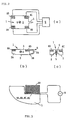
- Showing the main part of a slider of the embodiment of the present invention. Fig. 2(a) is a top view of the slider in which means for supplying AC voltages is shown. Fig. 2(b) is a plan view of the slider. Fig. 2(c) is a right side view of the slider.
- Fig. 3
- A partially enlarged cross-sectional view showing how piezo-electric elements are mounted on the slider.
- Fig. 4
- Showing the principles of operations of the piezo-electric elements used for the prevent invention. Fig. 4(a) shows a usual state where there is no supply of AC voltage.
- Fig. 4(b)
- shows a state where the piezo-electric elements are compressed by the supply of AC voltage. Fig. 4(c) shows a state where the piezo-electric elements are expanded by the supply of AC voltage.
- Fig. 5
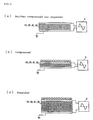
- Showing the vibration of the slider at the time when an AC voltage in the same phase is supplied to each of the piezo-electric elements on the slider shown in Fig. 2. Fig. 5(a) shows a state where the piezo-electric elements are compressed all together. Fig. 5(b) shows an usual state where piezo-electric elements are neither compressed nor expanded. Fig. 5(c) shows a state where the piezo-electric elements are expanded all together.
- Fig. 6
- Showing the vibration of the slider at the time when an AC voltage in reverse phase is supplied to each of the piezo-electric elements at the leading and the trailing ends on the slider shown in Fig. 2. Fig. 6(a) shows a state where the leading and the trailing piezo-electric elements are expanded and compressed, respectively. Fig. 6(b) shows a usual state where the piezo-electric elements are neither expanded nor compressed. Fig. 6(c) shows a state where the leading and the trailing piezo-electric elements are compressed and expanded, respectively.
- Fig. 7
- Showing that two AC voltages which are different in phase, in amplitude and in frequency are supplied to each of the piezo-electric elements on the slider shown in Fig. 2.
- Fig. 8
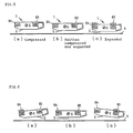
- Showing the operations of a magnetic disk apparatus using the vertical lift-off-and-landing type of slider in accordance with the present invention, in comparison with those of a magnetic disk apparatus using the conventional contact start-and-stop type of slider. Fig. 8(a) shows the velocity of rotation of the magnetic disk apparatus. Fig. 8(b) shows forces between the magnetic disk and the slider against each other. Fig. 8(c) shows the floating height of the slider.
- Fig. 1 to Fig. 8 shows a preferred embodiment of the present invention. At first, the embodiment is described by reference to Fig. 1 and Fig. 2. A
slider 1 has an air bearing surface (ABS) 2 and anopposite back surface 3 of theABS 2. TheABS 2 faces a disk surface, that is, arecording surface 4. Provided at the leading edge of theABS 2 in relative movement due to the rotation of a magnetic disk is a slantingsurface 2A through which a high-speed air flow gets into a gap between theABS 2 and thedisk surface 4 while the disk rotates so that buoyant force is applied to the slider. - On the other hand, provided at the trailing edge is a
gap 5B of amagnetic circuit 5A formed in atransducer 5 through which magnetized data is read from thedisk surface 4 or data is written to thedisk surface 4. Attached to theback surface 3 of theslider 1 is one end of asuspension 6, the other end of which is mounted on an actuator arm 7. The actuator arm 7 supports theslider 1 and moves it across thedisk surface 4 in the radial direction of the disk to position thegap 5B to a predetermined track on thesurface 4. Thesuspension 6 exerts resilient force on theslider 1 against the buoyancy of a high-speed air flow so that the slider is urged toward thedisk surface 4 and thereby thegap 5B of thetransducer 5 on theslider 1 flies over thedisk surface 4 at a predetermined height. - As shown in Fig. 2, disposed in four corners at the leading and the trailing edges on the
back surface 3 of theslider 1 are piezo-electric elements electric elements slider 1 with respect to the center of gravity G of theslider 1 and the piezo-electric elements electric elements slider 1 by sticking each block of the piezo-electric elements on theslider 1, or may be disposed, by spattering, in theslider 1. Connected to the piezo-electric elements electric elements slider 1, aweighty object 10 may be mounted. Theobject 10 makes theslider 1 vibrated largely according to the motions of the piezo-electric elements - As shown in Fig. 4, each of the piezo-
electric elements - As shown in Fig. 5, when an AC voltage in the same phase is applied to each of the piezo-
electric elements slider 1, it will contract and expand repeatedly in the same phase. When the piezo-electric elements slider 1 vibrates up and down in a horizontal posture at the state where the center of gravity G is maintained by a reaction of contraction or expansion. - Thereby a film of compressed air is formed between the
ABS 2 and thedisk surface 4 and theslider 1 can float, through the air film, over thesurface 4 of the disk at rest. - If the
slider 1 is at rest on thedisk surface 4 for a long time, and thereby stinction occurs between theslider 1 and thedisk surface 4, it may be difficult that by only the even up-and-down motion described above theslider 1 is broken away from thedisk surface 4. To overcome such difficulty, as shown in Fig. 6, it is preferable that AC voltages in opposite phase are applied to the piezo-electric elements slider 1 and the piezo-electric elements slider 1 can readily separate from the disk surface which is causing stinction. - It is easily understood that if AC voltages in reverse phase are applied to the piezo-
electric elements slider 1 and the piezo-electric elements slider 1, transversal oscillation (rolling) is made, and thereby theslider 1 can separate, similarly, from the disk surface which is causing stinction. AC voltages which are applied to the piezo-electric elements electric elements electric elements electric elements - Fig. 8 shows vertical-lift-off and vertical-landing motions of the
slider 1 with respect to the magnetic disk by means of the piezo-electric elements - At the time a before the magnetic disk rotates, the
slider 1 is vertically lifted off by supplying AC voltages to the piezo-electric elements. In this case, first AC voltages in reverse phase may be supplied to separate theslider 1 from the disk which is causing stinction and then AC voltages in the same phase may be supplied. At the time b when the rotation of the magnetic disk increases, the AC voltages supplied to the piezo-electric elements electric elements slider 1. At the time d when the disk stops rotating, the AC voltages are switched off to vertically land theslider 1 on the disk surface. - The lift-off and landing, thus obtained, of the slider in the vertical direction has, when comparing with the conventional contact start and stop method, the advantages of freedom from friction due to sliding between the magnetic disk and the slider at the time when the magnetic disk rotates at less than rotational velocity enough to fly the slider and less shock due to the collision of the magnetic disk with the slider.
- Further, as indicated by dotted lines f in Fig. 8(c), if the piezo-
electric elements slider 1 remain applied AC voltages of the same phase, the floating height of theslider 1 can be held greater. The higher floating can be used when high reliability is required to prevent head crush. When the AC voltages are switched off, as indicated by a solid line in Fig. 8(c), only floating due to an air flow occurs and a S/N ratio is improved although the floating height will decrease. - Described hitherto is the embodiment of the vertical lift-off-and-landing type of slider. However, it will be appreciated that the embodiment of the present invention may be applied also to the contact start-and-stop type of slider. In this case, as shown in Fig. 2, the piezo-
electric elements
Claims (7)
- An apparatus for moving a transducer (5) above a recording surface (4), comprising an air bearing slider (1) on which said transducer (5) as well as piezo-electric means are provided, an AC-voltage generating means (9) for activating said piezo-electric means so as to cause vibration of the air bearing slider (1), characterized in that said piezo-electric means comprises a plurality of piezo-electric elements (8A, 8B, 8C, 8D) and in that said AC-voltage generating means (9) is arranged so as to supply different AC voltages to different ones of said piezo-electric elements (8A, 8B, 8C, 8D) such that the air bearing slider (1) is caused to vibrate in a mode including at least one of rolling and pitching during liftoff of the slider (1) from the recording surface (4) so as to assist separation of the slider (1) from that recording surface (4).
- The apparatus according to claim 1, characterized in that said AC-voltage generating means supplies AC voltages of different frequency to piezo-electric elements (8A, 8B, 8C, 8D).
- The apparatus according to claim 1 or 2, characterized in that said AC-voltage generating means supplies AC voltages in different phase to said piezo-electric elements (8A, 8B, 8C, 8D).
- The apparatus according to one of claims 1 to 3, characterized in that a plurality of said piezo-electric elements (8A, 8B, 8C, 8D) are disposed at the leading and trailing ends of said slider (1).
- The apparatus according to one of claims 1 to 4, characterized in that a plurality of said piezo-electric elements (8A, 8B, 8C, 8D) are disposed on both sides of said slider (1).
- The apparatus according to one of claims 1 to 5, characterized in that a plurality of said piezo-electric elements (8A, 8B, 8C, 8D) are disposed on both sides of the leading and trailing ends of said slider (1).
- The apparatus according to one of claims 1 to 6, characterized by the use in a disk storage apparatus comprising a rotatable disk with said recording surface (4).
Applications Claiming Priority (3)
| Application Number | Priority Date | Filing Date | Title |
|---|---|---|---|
| JP260502/91 | 1991-09-12 | ||
| JP3260502A JPH06208771A (en) | 1991-09-12 | 1991-09-12 | Slider and disk recording apparatus using said slider |
| PCT/EP1992/001489 WO1993005508A1 (en) | 1991-09-12 | 1992-07-02 | Slider and disk storage apparatus with the slider |
Publications (2)
| Publication Number | Publication Date |
|---|---|
| EP0604434A1 EP0604434A1 (en) | 1994-07-06 |
| EP0604434B1 true EP0604434B1 (en) | 1995-10-04 |
Family
ID=17348861
Family Applications (1)
| Application Number | Title | Priority Date | Filing Date |
|---|---|---|---|
| EP92914374A Expired - Lifetime EP0604434B1 (en) | 1991-09-12 | 1992-07-02 | Disk storage apparatus with a slider |
Country Status (9)
| Country | Link |
|---|---|
| US (1) | US5313352A (en) |
| EP (1) | EP0604434B1 (en) |
| JP (1) | JPH06208771A (en) |
| KR (1) | KR930006687A (en) |
| CN (1) | CN1026836C (en) |
| CA (1) | CA2074018A1 (en) |
| DE (1) | DE69205286D1 (en) |
| HK (1) | HK204096A (en) |
| WO (1) | WO1993005508A1 (en) |
Families Citing this family (22)
| Publication number | Priority date | Publication date | Assignee | Title |
|---|---|---|---|---|
| US5486968A (en) * | 1993-11-10 | 1996-01-23 | International Business Machines Corporation | Method and apparatus for simultaneous write head planarization and lead routing |
| JPH08339676A (en) * | 1995-06-14 | 1996-12-24 | Hitachi Ltd | Magnetic disk unit |
| US5668690A (en) * | 1996-04-29 | 1997-09-16 | Harrison; Joshua C. | Method and apparatus for lifetime prediction of gas lubricated interfaces in data storage devices |
| US6002549A (en) * | 1996-11-01 | 1999-12-14 | Seagate Technology, Inc. | Dither microactors for stiction release in magnetic disc drives |
| US5943189A (en) * | 1996-12-05 | 1999-08-24 | Seagate Technology, Inc. | Piezoelectric engageable slider and slider microactuator |
| US5991113A (en) * | 1997-04-07 | 1999-11-23 | Seagate Technology, Inc. | Slider with temperature responsive transducer positioning |
| US5929326A (en) * | 1997-05-22 | 1999-07-27 | International Business Machines Corporation | Glide sensor integrated suspension |
| US6118637A (en) * | 1998-01-08 | 2000-09-12 | Seagate Technology, Inc. | Piezoelectric assembly for micropositioning a disc drive head |
| US6301080B1 (en) * | 1998-02-17 | 2001-10-09 | Seagate Technology Llc | Dither method to unload negative suction air bearings |
| JP2000011556A (en) | 1998-06-16 | 2000-01-14 | Alps Electric Co Ltd | Microactuator, magnetic head device and magnetic recording device |
| US6952330B1 (en) * | 1999-06-11 | 2005-10-04 | Seagate Technology Llc | Dynamic flying attitude control using augmented gimbal |
| US6290573B1 (en) | 1999-08-23 | 2001-09-18 | Komag, Incorporated | Tape burnish with monitoring device |
| US6735036B1 (en) | 2000-01-13 | 2004-05-11 | Seagate Technology Llc | Control of data sensor fly height |
| KR100438568B1 (en) * | 2000-12-28 | 2004-07-02 | 엘지전자 주식회사 | Apparatus for preventing contamination of optical head for near field recording |
| US6775103B2 (en) | 2001-04-02 | 2004-08-10 | Hitachi Global Storage Technologies Netherlands B.V. | Slider head having thermally controlled distal end and assembly with a rotating disc |
| ITTO20010519A1 (en) * | 2001-05-31 | 2002-12-01 | St Microelectronics Srl | ADJUSTABLE DEVICE, IN PARTICULAR RIGID DISC ACTUATOR DEVICE, WITH CONTROL OF THE ROLLING AND PICKING ANGLE. |
| KR100442871B1 (en) * | 2002-02-14 | 2004-08-02 | 삼성전자주식회사 | Head assembly and drive system employing it |
| US6947242B2 (en) * | 2002-04-16 | 2005-09-20 | Hitachi Global Storage Technologies Netherlands B.V. | Apparatus and method for dynamic fly height adjustment |
| US7009801B2 (en) * | 2003-09-25 | 2006-03-07 | Hitachi Global Storage Technologies Netherlands, B.V. | Method and apparatus for dynamically establishing roll static attitude in hard disk drive |
| US7072136B2 (en) * | 2003-09-25 | 2006-07-04 | Hitachi Global Storage Technologies Netherlands B.V. | Method and apparatus for dynamically establishing pitch static attitude in hard disk drive |
| US7064933B2 (en) * | 2003-10-22 | 2006-06-20 | Seagate Technology Llc | Structures for pole-tip actuation |
| US7724473B1 (en) * | 2004-04-29 | 2010-05-25 | Seagate Technology Llc | Slider with actuator-transducer separation and roll activation |
Family Cites Families (7)
| Publication number | Priority date | Publication date | Assignee | Title |
|---|---|---|---|---|
| JPS60245118A (en) * | 1984-05-18 | 1985-12-04 | 松下電器産業株式会社 | Electronic part |
| US4532802A (en) * | 1984-05-31 | 1985-08-06 | International Business Machines Corporation | Apparatus for analyzing the interface between a recording disk and a read-write head |
| JPH0752565B2 (en) * | 1985-02-25 | 1995-06-05 | 株式会社東芝 | Magnetic disk device |
| JPS62250570A (en) * | 1986-04-22 | 1987-10-31 | インタ−ナショナル ビジネス マシ−ンズ コ−ポレ−ション | Converter for memory |
| JPH01166382A (en) * | 1987-12-23 | 1989-06-30 | Hitachi Ltd | magnetic head slider |
| JPH033179A (en) * | 1989-05-31 | 1991-01-09 | Fujitsu Ltd | Magnetic head |
| US5021906A (en) * | 1989-10-31 | 1991-06-04 | International Business Machines Corporation | Programmable air bearing slider including magnetic read/write element |
-
1991
- 1991-09-12 JP JP3260502A patent/JPH06208771A/en active Pending
-
1992
- 1992-07-02 EP EP92914374A patent/EP0604434B1/en not_active Expired - Lifetime
- 1992-07-02 DE DE69205286T patent/DE69205286D1/en not_active Expired - Lifetime
- 1992-07-02 WO PCT/EP1992/001489 patent/WO1993005508A1/en not_active Ceased
- 1992-07-16 CA CA002074018A patent/CA2074018A1/en not_active Abandoned
- 1992-08-12 CN CN92109334A patent/CN1026836C/en not_active Expired - Fee Related
- 1992-08-12 KR KR1019920014486A patent/KR930006687A/en not_active Ceased
- 1992-09-11 US US07/943,612 patent/US5313352A/en not_active Expired - Fee Related
-
1996
- 1996-11-07 HK HK204096A patent/HK204096A/en not_active IP Right Cessation
Also Published As
| Publication number | Publication date |
|---|---|
| JPH06208771A (en) | 1994-07-26 |
| EP0604434A1 (en) | 1994-07-06 |
| CA2074018A1 (en) | 1993-03-13 |
| HK204096A (en) | 1996-11-15 |
| CN1026836C (en) | 1994-11-30 |
| DE69205286D1 (en) | 1995-11-09 |
| KR930006687A (en) | 1993-04-21 |
| CN1070503A (en) | 1993-03-31 |
| US5313352A (en) | 1994-05-17 |
| WO1993005508A1 (en) | 1993-03-18 |
Similar Documents
| Publication | Publication Date | Title |
|---|---|---|
| US5313352A (en) | Magnetic disk slider having piezo-electric vibration elements | |
| US6317294B1 (en) | Slider with negative and multiple positive pressure generation portions and head including the same | |
| US7209323B2 (en) | Slider having cavity floor with differing depths | |
| US6462909B1 (en) | Disc head slider having wear-resistant pads for enhanced damping | |
| KR960009887B1 (en) | Data storage and disk surface cleaning method | |
| US4530021A (en) | Micromotion release of heads from lubricated magnetic disks | |
| US6952330B1 (en) | Dynamic flying attitude control using augmented gimbal | |
| US6680821B2 (en) | Slider air bearing surface having improved fly height profile characteristics | |
| US6958889B2 (en) | Slider with a compliant transducer interface | |
| KR100442871B1 (en) | Head assembly and drive system employing it | |
| US6674611B2 (en) | Air bearing design producing steeper ramp profile near the laser texture zone | |
| US6510027B1 (en) | Disc head slider having highly damped bearing with multiple pressure gradiant-generating pads | |
| JPH0346114A (en) | magnetic recording and reproducing device | |
| US6437948B1 (en) | Disk unit having a head suspension | |
| Harrison et al. | An explanation of the observed frequency domain behavior of head-disk interface resonances in the proximity recording regime | |
| JPS61230687A (en) | Slider for recording converter | |
| JP3064634B2 (en) | Disk drive device | |
| JPS63251909A (en) | Magnetic disk device | |
| JPH03219473A (en) | Transducer supporting device | |
| JP3289316B2 (en) | Flying magnetic head device | |
| JP3077352B2 (en) | Magnetic disk drive | |
| KR100265942B1 (en) | Apparatus for recording/reading out information on to/from information media | |
| JP2653350B2 (en) | Information reading head support device | |
| JPH01146175A (en) | Head floating device | |
| JP4181064B2 (en) | Manufacturing method of recording medium |
Legal Events
| Date | Code | Title | Description |
|---|---|---|---|
| PUAI | Public reference made under article 153(3) epc to a published international application that has entered the european phase |
Free format text: ORIGINAL CODE: 0009012 |
|
| 17P | Request for examination filed |
Effective date: 19930625 |
|
| AK | Designated contracting states |
Kind code of ref document: A1 Designated state(s): CH DE FR GB IT LI NL |
|
| 17Q | First examination report despatched |
Effective date: 19941006 |
|
| GRAA | (expected) grant |
Free format text: ORIGINAL CODE: 0009210 |
|
| AK | Designated contracting states |
Kind code of ref document: B1 Designated state(s): CH DE FR GB IT LI NL |
|
| PG25 | Lapsed in a contracting state [announced via postgrant information from national office to epo] |
Ref country code: NL Free format text: LAPSE BECAUSE OF FAILURE TO SUBMIT A TRANSLATION OF THE DESCRIPTION OR TO PAY THE FEE WITHIN THE PRESCRIBED TIME-LIMIT Effective date: 19951004 Ref country code: LI Effective date: 19951004 Ref country code: IT Free format text: LAPSE BECAUSE OF FAILURE TO SUBMIT A TRANSLATION OF THE DESCRIPTION OR TO PAY THE FEE WITHIN THE PRESCRIBED TIME-LIMIT;WARNING: LAPSES OF ITALIAN PATENTS WITH EFFECTIVE DATE BEFORE 2007 MAY HAVE OCCURRED AT ANY TIME BEFORE 2007. THE CORRECT EFFECTIVE DATE MAY BE DIFFERENT FROM THE ONE RECORDED. Effective date: 19951004 Ref country code: FR Effective date: 19951004 Ref country code: CH Effective date: 19951004 |
|
| RAP2 | Party data changed (patent owner data changed or rights of a patent transferred) |
Owner name: INTERNATIONAL BUSINESS MACHINES CORPORATION Owner name: IBM DEUTSCHLAND GMBH |
|
| REF | Corresponds to: |
Ref document number: 69205286 Country of ref document: DE Date of ref document: 19951109 |
|
| NLT2 | Nl: modifications (of names), taken from the european patent patent bulletin |
Owner name: INTERNATIONAL BUSINESS MACHINES CORPORATION |
|
| PG25 | Lapsed in a contracting state [announced via postgrant information from national office to epo] |
Ref country code: DE Effective date: 19960105 |
|
| EN | Fr: translation not filed | ||
| NLV1 | Nl: lapsed or annulled due to failure to fulfill the requirements of art. 29p and 29m of the patents act | ||
| REG | Reference to a national code |
Ref country code: CH Ref legal event code: PL |
|
| PLBE | No opposition filed within time limit |
Free format text: ORIGINAL CODE: 0009261 |
|
| STAA | Information on the status of an ep patent application or granted ep patent |
Free format text: STATUS: NO OPPOSITION FILED WITHIN TIME LIMIT |
|
| 26N | No opposition filed | ||
| PGFP | Annual fee paid to national office [announced via postgrant information from national office to epo] |
Ref country code: GB Payment date: 19990629 Year of fee payment: 8 |
|
| PG25 | Lapsed in a contracting state [announced via postgrant information from national office to epo] |
Ref country code: GB Free format text: LAPSE BECAUSE OF NON-PAYMENT OF DUE FEES Effective date: 20000702 |
|
| GBPC | Gb: european patent ceased through non-payment of renewal fee |
Effective date: 20000702 |