EP0604400A2 - Clipless bicycle pedal system - Google Patents
Clipless bicycle pedal system Download PDFInfo
- Publication number
- EP0604400A2 EP0604400A2 EP94103006A EP94103006A EP0604400A2 EP 0604400 A2 EP0604400 A2 EP 0604400A2 EP 94103006 A EP94103006 A EP 94103006A EP 94103006 A EP94103006 A EP 94103006A EP 0604400 A2 EP0604400 A2 EP 0604400A2
- Authority
- EP
- European Patent Office
- Prior art keywords
- pedal
- cleat
- groove
- resilient tongue
- recessed area
- Prior art date
- Legal status (The legal status is an assumption and is not a legal conclusion. Google has not performed a legal analysis and makes no representation as to the accuracy of the status listed.)
- Granted
Links
Images


Classifications
-
- B—PERFORMING OPERATIONS; TRANSPORTING
- B62—LAND VEHICLES FOR TRAVELLING OTHERWISE THAN ON RAILS
- B62M—RIDER PROPULSION OF WHEELED VEHICLES OR SLEDGES; POWERED PROPULSION OF SLEDGES OR SINGLE-TRACK CYCLES; TRANSMISSIONS SPECIALLY ADAPTED FOR SUCH VEHICLES
- B62M3/00—Construction of cranks operated by hand or foot
- B62M3/08—Pedals
- B62M3/086—Attachments between shoe and pedal other than toe clips, e.g. cleats
-
- Y—GENERAL TAGGING OF NEW TECHNOLOGICAL DEVELOPMENTS; GENERAL TAGGING OF CROSS-SECTIONAL TECHNOLOGIES SPANNING OVER SEVERAL SECTIONS OF THE IPC; TECHNICAL SUBJECTS COVERED BY FORMER USPC CROSS-REFERENCE ART COLLECTIONS [XRACs] AND DIGESTS
- Y10—TECHNICAL SUBJECTS COVERED BY FORMER USPC
- Y10T—TECHNICAL SUBJECTS COVERED BY FORMER US CLASSIFICATION
- Y10T74/00—Machine element or mechanism
- Y10T74/21—Elements
- Y10T74/2164—Cranks and pedals
- Y10T74/2168—Pedals
- Y10T74/217—Pedals with toe or shoe clips
Definitions
- the invention herein relates to bicycle equipment. More particularly it relates to pedal-and-cleat systems commonly referred to as "clipless bicycle pedals.”
- asymmetrical design of prior art pedals means that there is only one orientation in which the pedal may be used.
- the rider must hunt for the proper alignment before engaging the cleat in the pedal, with many of the smaller designs requiring careful and conscious placement of the foot. This can distract the rider from watching for road hazards and can hinder takeoff from a stop. A slip of the foot while attempting to engage the pedal and cleat most often results in a painful fall onto the bicycle crossbar.
- Some asymmetric design clipless pedals have included a means to enable the rider to more easily find the pedal and engage it with the cleat. These pedals utilize a spring or clip which is released when the rider removes his foot from the pedal. The spring presses against the axle causing the pedal to stay upright after it is disengaged. The spring is compressed again when the cleat engages the pedal, allowing free rotation of the pedal.
- a clipless pedal system in accordance with the present invention comprises: a pedal and a cleat, the pedal consisting of an axle attached to the end of a crank arm on which is mounted a block.
- the block has a generally convex symmetrical curved top and bottom surface, and is generally circular in the lateral plane.
- a plurality of grooves is formed in the circumferential edge of the pedal block, with at least one groove toward the leading edge of the pedal block and one toward the trailing edge.
- the cleat comprises a plate fixed to the sole of a rider's shoe, projecting downwardly therefrom.
- the plate has a concave recess which corresponds to the convex surface of the pedal block when the plate is brought into contact with the pedal block.
- Contained in the recess of the plate is an engaging means which comprises a tongue portion adapted to be removably seated in one of the grooves in the pedal block.
- An urging means cooperates with the tongue portion to releasably secure the rider's shoe to the pedal.
- Figure 1 is a side elevation view of a typical bicycle illustrating a longitudinal plane which will be used as a point of reference for the description of the invention.
- Figure 2 is an enlarged top plan view of the pedal assembly illustrating an axis and a lateral plane which will be used as points of reference for the description of the invention.
- Figure 3 is a perspective view of the pedal and cleat separated.
- Figure 4 is a side elevation view of the pedal and cleat engaged and latched with the cleat secured to the shoe.
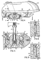
- Figure 5 is a sectional view taken on line 5-5 of Figure 4.
- Figure 6 is an underside view showing the shoe rotated to disengage the cleat from the pedal.
- Figure 7 is a sectional view taken on line 7-7 of Figure 4.
- Figure 8 is a partial sectional view taken on line 5-5 of Figure 4 of an alternate embodiment of the invention.
- Figure 9 is a partial sectional view taken on line 5-5 of Fig. 4 of a second alternate embodiment of the invention.
- Figure 10 is a side elevation view, partially cut away, of another embodiment of the pedal-and-cleat system of this invention.
- Figure 11 is a plan view of the pedal of Figure 10.
- Figure 12 is a front elevation view, partially in section, illustrating the locking mechanism between the pedal and cleat of the system of Figure 10.
- FIGS 1, 2 and 3 illustrate the pedal 12 and cleat 4 generally and their relation to the bicycle.
- pedal 12 comprises pedal block 12' attached to axle 14 by bolt 18.
- Bolt 18 is preferably a hex bolt with a tapered head but may be any other type of bolt which will attach the pedal to axle 14 to allow free rotation of the pedal around the axle.
- Axle 14 screws into crank 22 by means of right or left-handed threads, depending on whether it is the right or left pedal, so the axle does not come unscrewed when the pedal is pushed.
- the structures of pedal 12, cleat 4 and their cooperative relationship are the critical elements of this invention.
- the block 12' of pedal 12 has a generally circular shape in lateral plane 3 defined by arrow 3.
- block 12' When bisected by a plane parallel to the longitudinal plane defined by arrow 2 in Figure 1, block 12' is symmetrically convex with equivalent flat spots 24 on the top and bottom of the pedal.
- the flat spot 24 which at any time is uppermost provides the contact surface for sole 26 of shoe 25.
- the right and left pedals are identical, except that (as is conventional) the axles for the left and right sides of the bicycle require left and right hand threads, respectively.
- Pedal 12 may be made of any lightweight rigid material which is durable when subjected to stresses related to bicycle riding. The material should be able to withstand impact without fracturing or deforming. Preferred are aluminum or titanium, but rigid durable plastics may also be used. Similar or identical material may be used for cleat 4, although plastics are preferred to metals for comfort in walking.
- Cleat 4 has a recessed area 11 into which pedal 12 is to be inserted.
- the depth is not critical, but preferably, the depth of recessed area 11 is slightly more than half the depth of block 12' -- enough to allow secure insertion of the pedal.
- Cutout 9 in the center of cleat 4 allows contact between shoe sole 26 and pedal 12 when the pedal 12 and cleat 4 are connected.
- Mounting holes 8 formed in cleat 4 are spaced so as to fit commercially available shoes. Mounting holes 8 (as shown in Figure 6) are elongated so as to allow for adjustment in the location of the cleat with respect to the pre-drilled holes and the sole of the shoe.
- pedal 12 and cleat 4 The cooperation between pedal 12 and cleat 4 is illustrated in Figure 4.
- the rider places the shoe 25 with cleat 4 over pedal 12.
- the symmetrical curved top surface of the pedal centers the recessed area 11 over pedal 12, guiding cleat 4 to its proper position. Even if the pedal is not parallel to lateral plane 3 at the time the rider initially attempts to engage cleat 4 and pedal 12, the curved surface 13 of pedal 12 will cause block 12' to rotate so that cleat 4 is centered over pedal 12.
- tongue 5 and tongue 6 fit into grooves 16 and 17, respectively. Because block 12' is symmetrical at the top and bottom, grooves 16 and 17 are interchangeable so that tongue 5 can be inserted into groove 17 and tongue 6 can be inserted into groove 16 when the block 12' is turned over.
- Figure 4 also illustrates the means of attaching cleat 4 to shoe sole 26.
- Fasteners 28 (which may be screws, bolts, or equivalent fasteners) are inserted through mounting holes 8 and into aligned pre-drilled, threaded holes 27 in the sole of the shoe.
- Tongues 5 and 6 which are flat plates of either durable plastic or lightweight metal are shown engaged in the grooves 16 and 17 of pedal 12 in Figure 5. Tongues 5 and 6 are pressed into grooves 16 and 17 by springs 30. When the curved surfaces 13 of block 12' press against either tongue, spring 30 is depressed and the tongue retracts into cavity 29. Insertion of pedal 12 into the recessed area 11 such that tongues 5 and 6 are aligned with grooves 16 and 17 causes springs 30 to resile, pressing the tongues into the grooves.
- each tongue and spring combination is replaced with a flexible wire 40 which is attached to opposing pegs or screws 42.
- the wire has a spring quality such that it can be depressed to allow pedal 12 to enter recessed area 11, but will snap back into grooves 16 and 17 when wire 40 and the grooves are aligned.
- the wire In order for cleat 4 to be held to pedal 12 against the forces exerted while pedaling, the wire must have sufficient stiffness that it will retain the connection between the cleat and the pedal against sudden motions of the rider's foot.
- FIG. 9 Another alternate embodiment, shown in Figure 9, replaces the flat plate tongues with a rod 46 which is attached to the spring 30. Both the rod 46 and the spring 30 are held in place within cavity 29 by pegs or screws 48.
- Groove length and depth are large enough to retain the connection against sudden motions of the rider's foot which are encountered, for example, when climbing hills or when starting from a full stop but not so great as to make disengagement of the pedal and cleat overly difficult.
- Free rotation of block 12' around the axle 14 is enabled by sets of ball bearings 34 shown in Figure 5.
- Two ball bearing sets 34 are shown; however, any number of ball bearing sets which allow free rotation of the pedal around the axle will serve the purpose.
- Bearings 34 and the axle portions internal to the pedal should be protected by a washer 38 and any other method to prevent dirt from entering the interior of the pedal and clogging the bearings.
- the cleat 4 shown in cross-section in Figure 4 will preferably have sloped edges at the leading and trailing edges of the cleat 44 and 46, respectively, to decrease wind resistance while riding and to enable the rider to walk after dismounting the bike.
- the sloped or curved edges of the cleat will allow the rider to walk with a rolling motion rather than awkwardly trying to avoid putting any weight on the protruding knobs or abrupt edges that are present in most clipless pedal systems.
- the generally flat profile of cleat 4 protects the critical parts of the fastening mechanism which are contained within recessed area 11. Tongues 5 and 6, or wires 40, are shielded from breakage or wear associated with walking on the cleat.
- the shallow profile of the pedal shown in Fig. 7 illustrates that the bottom of pedal 12 extends only a small distance beyond crank 22 at the lowest point in its rotation.
- the low profile allows the rider to continue pedaling while maintaining a steep lean angle for cornering.
- the outer portion of block 12' is cut away or truncated as shown at 32 to provide a recess for the end of axle 14 and attaching bolt 18. This prevents the axle 14 from extending beyond the outer side of block 12' and allows the rider to make turns at a steeper angle without striking the end of the pedal on the road.
- FIG. 10-12 Another embodiment of the pedal and cleat engagement is illustrated in Figures 10-12.
- the block 12' has fixed grooves 60 (preferably three) spaced apart around its circumference. These grooves align with tongues 64 of cleat 4, but the width of each tongue 60 is less than the length of the corresponding groove 60.
- the tongues 60 of the cleat 4 align with the open top end portion 62 of groove 60, which provides access to the remainder of the groove 60.
- That open portion 62 is, however, oriented to be out of alignment with the longitudinal axis 1 of the pedal, so that in order to line up the tongues 64 and grooves 60 the rider's foot must be turned away from that axis 1 to the axis shown as 1' and indicated by the double-headed arrow 71.
- the rider then pushes his or her foot downward into the opening 62 until the bottom of the tongue 64 contacts the floor of groove 60 under the opening 62. Then the rider rotates his or her foot back to the axis 1 and the tongue 64 slides along groove 60 past shoulder 63 into recessed portion 67, where it is locked into position.
- Coil spring 65 rotating on pivot 66 and with one end 69 locked in socket 68 and the other end 70 fitted into a hole 72 in tongue 64, urges the tongue 64 into continual engagement with portion 67 of the groove 60.
- the block 12' has pairs of grooves (designated as 60 and 60') on opposite sides of the block 12', so that no matter which side is up the rider's shoe cleat 4 will be engageable with the pedal 12.
- the portions of the grooves 60' shown in Figure 12 are labelled with primes to indicated the correspondence with the equivalent portions of the grooves 60.
Abstract
Description
- The invention herein relates to bicycle equipment. More particularly it relates to pedal-and-cleat systems commonly referred to as "clipless bicycle pedals."
- In recent years clipless bicycle pedals have become increasingly popular among bicyclists who participate in both touring and racing. The old style toe clip pedal often caused discomfort by placing pressure on the top of the foot and could tend to be awkward and bulky for racers. Major advantages of the clipless pedals are comfort and aerodynamics.
- However, current designs of clipless pedals have a number of problems. Most current styles of clipless pedals use a ski binding principle which requires setting a tension to properly engage and disengage the pedal using a single spring which presses the cleat forward against a groove/tab combination at the front of the pedal. Even if properly set, however, a strong movement of the foot (for example taking off from a stop) could result in accidental release causing the rider to fall. In other instances if the tension is improperly set it may become too difficult for the rider to release his foot once it is engaged in the pedal, also causing a possibility of fall. Some styles of pedals hold the foot too rigidly, preventing natural rotation of the knee as the bike is being pedaled. This often results in knee injury to avid cyclists. While some styles of clipless pedals have been designed to compensate for natural rotation of the knee, they have given up some of the firmness with which the foot is secured to the pedal.
- Another problem is the high profile of some pedals which interferes with pedaling while cornering. Insufficient pedal clearance while turning is one of the primary causes of accidents during bicycle competitions. The rider must stop pedaling through the turn or risk hitting the pedal on the ground. Striking a pedal on the ground during a turn lifts the bike's rear wheel off the ground with the bicycle pivoting on the pedal. This inevitably results in a fall.
- Further, the asymmetrical design of prior art pedals means that there is only one orientation in which the pedal may be used. The rider must hunt for the proper alignment before engaging the cleat in the pedal, with many of the smaller designs requiring careful and conscious placement of the foot. This can distract the rider from watching for road hazards and can hinder takeoff from a stop. A slip of the foot while attempting to engage the pedal and cleat most often results in a painful fall onto the bicycle crossbar. Some asymmetric design clipless pedals have included a means to enable the rider to more easily find the pedal and engage it with the cleat. These pedals utilize a spring or clip which is released when the rider removes his foot from the pedal. The spring presses against the axle causing the pedal to stay upright after it is disengaged. The spring is compressed again when the cleat engages the pedal, allowing free rotation of the pedal.
- Another major disadvantage of many of the clipless pedal systems is the size of the cleat extending downward from the bottom of the shoe. The knobby protrusions of the cleats often make it awkward or impossible to walk without falling or ruining the cleat.
- It would therefore be advantageous to have a low profile symmetrical pedal which is easy to engage and disengage yet will firmly hold the cleat against pressure of normal riding. While it is recognized that the cleat is required to extend a certain distance from the bottom of the shoe, it would be preferable to have a flat rather than a knobby cleat protruding from the bottom of the shoe which will enable the rider to walk once he leaves his bicycle.
- The present invention proposes a clipless pedal system which is easily engaged and released, when desired, and which allows a high cornering angle due to the pedal's shallow, symmetrical design. A clipless pedal system in accordance with the present invention comprises: a pedal and a cleat, the pedal consisting of an axle attached to the end of a crank arm on which is mounted a block. The block has a generally convex symmetrical curved top and bottom surface, and is generally circular in the lateral plane. A plurality of grooves is formed in the circumferential edge of the pedal block, with at least one groove toward the leading edge of the pedal block and one toward the trailing edge.
- The cleat comprises a plate fixed to the sole of a rider's shoe, projecting downwardly therefrom. The plate has a concave recess which corresponds to the convex surface of the pedal block when the plate is brought into contact with the pedal block. Contained in the recess of the plate is an engaging means which comprises a tongue portion adapted to be removably seated in one of the grooves in the pedal block. An urging means cooperates with the tongue portion to releasably secure the rider's shoe to the pedal.
- (For brevity herein, the entire system will often be referred to as the "clipless pedal" or "clipless pedal system," including both the pedal itself and the cleat, as this terminology is common in the art. It will be readily determinable by those skilled in the art when the discussion below refers to the system and when it refers separately to the pedal or the pedal block.)
- Figure 1 is a side elevation view of a typical bicycle illustrating a longitudinal plane which will be used as a point of reference for the description of the invention.
- Figure 2 is an enlarged top plan view of the pedal assembly illustrating an axis and a lateral plane which will be used as points of reference for the description of the invention.
- Figure 3 is a perspective view of the pedal and cleat separated.
- Figure 4 is a side elevation view of the pedal and cleat engaged and latched with the cleat secured to the shoe.
- Figure 5 is a sectional view taken on line 5-5 of Figure 4.
- Figure 6 is an underside view showing the shoe rotated to disengage the cleat from the pedal.
- Figure 7 is a sectional view taken on line 7-7 of Figure 4.
- Figure 8 is a partial sectional view taken on line 5-5 of Figure 4 of an alternate embodiment of the invention.
- Figure 9 is a partial sectional view taken on line 5-5 of Fig. 4 of a second alternate embodiment of the invention.
- Figure 10 is a side elevation view, partially cut away, of another embodiment of the pedal-and-cleat system of this invention.
- Figure 11 is a plan view of the pedal of Figure 10.
- Figure 12 is a front elevation view, partially in section, illustrating the locking mechanism between the pedal and cleat of the system of Figure 10.
- The invention herein will be most readily understood by reference to the drawings. Figures 1, 2 and 3 illustrate the
pedal 12 andcleat 4 generally and their relation to the bicycle. The basic connections are conventional. In particular,pedal 12 comprises pedal block 12' attached toaxle 14 bybolt 18.Bolt 18 is preferably a hex bolt with a tapered head but may be any other type of bolt which will attach the pedal toaxle 14 to allow free rotation of the pedal around the axle.Axle 14 screws intocrank 22 by means of right or left-handed threads, depending on whether it is the right or left pedal, so the axle does not come unscrewed when the pedal is pushed. - The structures of
pedal 12,cleat 4 and their cooperative relationship are the critical elements of this invention. The block 12' ofpedal 12 has a generally circular shape inlateral plane 3 defined byarrow 3. Formed in thecircumferential side 100 of block 12' (which side is preferably flattened as shown in Figure 3) aregrooves lateral plane 3 and which are disposed spaced apart from each other around the circumference of block 12'. Generally there are two grooves, as 16 and 17, located diametrically opposite to each other. It would also be possible to have each of these grooves be divided into smaller adjoining grooves. Alternatively, there may be three grooves disposed 120° apart, in the manner shown for a different embodiment in Figure 11. However, since more grooves do not markedly improve the performance of the pedal system over that obtained with two or three grooves, the latter are preferred. The discussion herein will be in terms of the two- or three- groove system, as indicated, although those skilled in the art will recognize the applicability of the discussion to other numbers of grooves. - When bisected by a plane parallel to the longitudinal plane defined by
arrow 2 in Figure 1, block 12' is symmetrically convex with equivalentflat spots 24 on the top and bottom of the pedal. Theflat spot 24 which at any time is uppermost provides the contact surface for sole 26 ofshoe 25. The right and left pedals are identical, except that (as is conventional) the axles for the left and right sides of the bicycle require left and right hand threads, respectively. -
Pedal 12 may be made of any lightweight rigid material which is durable when subjected to stresses related to bicycle riding. The material should be able to withstand impact without fracturing or deforming. Preferred are aluminum or titanium, but rigid durable plastics may also be used. Similar or identical material may be used forcleat 4, although plastics are preferred to metals for comfort in walking. -
Cleat 4 has a recessed area 11 into whichpedal 12 is to be inserted. The depth is not critical, but preferably, the depth of recessed area 11 is slightly more than half the depth of block 12' -- enough to allow secure insertion of the pedal.Cutout 9 in the center ofcleat 4 allows contact between shoe sole 26 andpedal 12 when thepedal 12 andcleat 4 are connected. Mountingholes 8 formed incleat 4 are spaced so as to fit commercially available shoes. Mounting holes 8 (as shown in Figure 6) are elongated so as to allow for adjustment in the location of the cleat with respect to the pre-drilled holes and the sole of the shoe. - The cooperation between
pedal 12 andcleat 4 is illustrated in Figure 4. The rider places theshoe 25 withcleat 4 overpedal 12. The symmetrical curved top surface of the pedal centers the recessed area 11 overpedal 12, guidingcleat 4 to its proper position. Even if the pedal is not parallel tolateral plane 3 at the time the rider initially attempts to engagecleat 4 andpedal 12, thecurved surface 13 ofpedal 12 will cause block 12' to rotate so thatcleat 4 is centered overpedal 12. When pedal 12 is fully inserted intocleat 4,tongue 5 andtongue 6 fit intogrooves grooves tongue 5 can be inserted intogroove 17 andtongue 6 can be inserted intogroove 16 when the block 12' is turned over. - Figure 4 also illustrates the means of attaching
cleat 4 toshoe sole 26. Fasteners 28 (which may be screws, bolts, or equivalent fasteners) are inserted through mountingholes 8 and into aligned pre-drilled, threadedholes 27 in the sole of the shoe. -
Tongues grooves pedal 12 in Figure 5.Tongues grooves springs 30. When thecurved surfaces 13 of block 12' press against either tongue,spring 30 is depressed and the tongue retracts intocavity 29. Insertion ofpedal 12 into the recessed area 11 such thattongues grooves - In an alternate embodiment, shown in Figure 8, each tongue and spring combination is replaced with a
flexible wire 40 which is attached to opposing pegs or screws 42. The wire has a spring quality such that it can be depressed to allowpedal 12 to enter recessed area 11, but will snap back intogrooves wire 40 and the grooves are aligned. In order forcleat 4 to be held to pedal 12 against the forces exerted while pedaling, the wire must have sufficient stiffness that it will retain the connection between the cleat and the pedal against sudden motions of the rider's foot. - Another alternate embodiment, shown in Figure 9, replaces the flat plate tongues with a
rod 46 which is attached to thespring 30. Both therod 46 and thespring 30 are held in place withincavity 29 by pegs or screws 48. - When the rider wishes to disengage the pedal the foot is rotated as shown in Figure 6. Once the foot is rotated sufficiently the grooves will no longer be aligned with the tongues.
End 35 ofgroove tongues grooves 15 and 16 the point at which end 35 of the groove initiates depression of the spring may be predetermined. The amount of rotation of the foot required to disengage the pedal can be optimized to prevent unintentional disconnection while still allowing intentional removal of the foot from the pedal with a minimal rotation, typically 10 to 15 degrees. Groove length and depth are large enough to retain the connection against sudden motions of the rider's foot which are encountered, for example, when climbing hills or when starting from a full stop but not so great as to make disengagement of the pedal and cleat overly difficult. Normal rotations of the foot which are required for knee flexions, usually less than 5 degrees, are not sufficient to cause the springs to be depressed sufficiently to disengage the pedal. - Free rotation of block 12' around the
axle 14 is enabled by sets ofball bearings 34 shown in Figure 5. As the pedal is pressedshoe 25 remains essentially parallel to the ground whileaxle 14 transfers the force of the rider's pedaling to crank 25. Two ball bearing sets 34 are shown; however, any number of ball bearing sets which allow free rotation of the pedal around the axle will serve the purpose.Bearings 34 and the axle portions internal to the pedal should be protected by awasher 38 and any other method to prevent dirt from entering the interior of the pedal and clogging the bearings. - The
cleat 4 shown in cross-section in Figure 4 will preferably have sloped edges at the leading and trailing edges of thecleat cleat 4 protects the critical parts of the fastening mechanism which are contained within recessed area 11.Tongues wires 40, are shielded from breakage or wear associated with walking on the cleat. - The shallow profile of the pedal shown in Fig. 7 illustrates that the bottom of
pedal 12 extends only a small distance beyond crank 22 at the lowest point in its rotation. The low profile allows the rider to continue pedaling while maintaining a steep lean angle for cornering. Also, advantageously the outer portion of block 12' is cut away or truncated as shown at 32 to provide a recess for the end ofaxle 14 and attachingbolt 18. This prevents theaxle 14 from extending beyond the outer side of block 12' and allows the rider to make turns at a steeper angle without striking the end of the pedal on the road. - Another embodiment of the pedal and cleat engagement is illustrated in Figures 10-12. In this alternate embodiment the block 12' has fixed grooves 60 (preferably three) spaced apart around its circumference. These grooves align with
tongues 64 ofcleat 4, but the width of eachtongue 60 is less than the length of the correspondinggroove 60. When the rider's foot is off thepedal 12, thetongues 60 of thecleat 4 align with the opentop end portion 62 ofgroove 60, which provides access to the remainder of thegroove 60. Thatopen portion 62 is, however, oriented to be out of alignment with the longitudinal axis 1 of the pedal, so that in order to line up thetongues 64 andgrooves 60 the rider's foot must be turned away from that axis 1 to the axis shown as 1' and indicated by the double-headedarrow 71. The rider then pushes his or her foot downward into theopening 62 until the bottom of thetongue 64 contacts the floor ofgroove 60 under theopening 62. Then the rider rotates his or her foot back to the axis 1 and thetongue 64 slides alonggroove 60past shoulder 63 into recessedportion 67, where it is locked into position.Coil spring 65, rotating onpivot 66 and with oneend 69 locked insocket 68 and theother end 70 fitted into ahole 72 intongue 64, urges thetongue 64 into continual engagement withportion 67 of thegroove 60. - It will be noted from Figure 12 that the block 12' has pairs of grooves (designated as 60 and 60') on opposite sides of the block 12', so that no matter which side is up the rider's
shoe cleat 4 will be engageable with thepedal 12. (The portions of the grooves 60' shown in Figure 12 are labelled with primes to indicated the correspondence with the equivalent portions of thegrooves 60.) - It will be evident that there are additional embodiments which are not illustrated above but which are clearly within the scope and spirit of the present invention. The above description and drawings are therefore intended to be exemplary only and the scope of the invention is to be limited solely by the appended claims.
Claims (11)
- A bicycle pedal system for releasably binding the sole of a rider's shoe to a pedal rotatably attached to a spindle, the pedal system comprising:
a pedal body having a generally circular shape with a top, a bottom, and an edge having an edge length extending around said generally circular shape, said edge having an inside portion where said spindle may be attached perpendicular to said edge, and a leading portion and a trailing portion, each having a groove therein parallel to said edge length, said groove having two ends, said top and said bottom being symmetrical along a plane bisecting said pedal body; and
a cleat assembly comprising:
a cleat plate for attachment to said sole and projecting downwardly therefrom, said cleat having a recessed area for accepting a top or a bottom of said pedal body;
a cleat locking mechanism disposed within said cleat having a resilient tongue portion extending at least partially into said recessed area at a front portion and a rear portion of said recessed area, said resilient tongue portion fitting within a corresponding groove in said pedal body when said top or said bottom of said pedal body is disposed within said recessed area to releasably bind said pedal body to said cleat assembly;
wherein said pedal body is released from said cast assembly by rotation of said rider's shoe with respect to said pedal body thereby depressing said resilient tongue portion and releasing said resilient tongue portion from said groove. - A bicycle pedal system as in Claim 1 wherein said top and said bottom are at least partially convex.
- A bicycle pedal system as in Claim 1 wherein said resilient tongue portion comprises a spring wire, a portion of which spans said recessed area.
- A bicycle pedal system as in Claim 1 where said resilient tongue portion comprises a plate urged toward said recessed area by a spring.
- A bicycle pedal system as in Claim 1 wherein at least a portion of said recessed area is concave.
- A bicycle pedal system as in Claim 1 where said groove has a length whereby rotation of said rider's shoe within the range of 10 to 15 degrees will release said resilient tongue portion from said groove.
- A bicycle pedal system as in Claim 1 wherein said groove and its corresponding said resilient tongue portion are configured to cooperate so that when said pedal body is inserted into said recessed area, said resilient tongue portion is forced to retract at least partially from said recessed area.
- A bicycle pedal system as in Claim 1 where said groove and its corresponding said resilient tongue portion are configured to cooperate so that when said pedal body is fully disposed within said recessed area, said resilient tongue portion resiles into said groove.
- A pedal for a clipless bicycle pedal system comprising:
a body having a generally circular shape which is symmetrical from a top to a bottom and having an edge between said top end said bottom wherein a plurality of grooves is formed with said grooves parallel to said edge, said grooves being distributed generally diametrically opposite each other around said body; and
means for rotatably attaching a spindle to said body perpendicular to said edge;
wherein said grooves are adapted to each accept a resilient tongue means of a corresponding cleat to releasably retain said pedal to said cleat when said pedal is disposed within said cleat. - A pedal as in Claim 1 wherein said top and said bottom are at least partially convex.
- A pedal as in Claim 1 wherein a first groove of said plurality of grooves is disposed at a leading edge of said body and a second groove is disposed at a trailing edge of said body.
Applications Claiming Priority (3)
| Application Number | Priority Date | Filing Date | Title |
|---|---|---|---|
| US377223 | 1982-05-11 | ||
| US07/377,223 US4942778A (en) | 1989-07-10 | 1989-07-10 | Clipless bicycle pedal system |
| EP90306912A EP0408208B1 (en) | 1989-07-10 | 1990-06-25 | Clipless bicycle pedal system |
Related Parent Applications (1)
| Application Number | Title | Priority Date | Filing Date |
|---|---|---|---|
| EP90306912.8 Division | 1990-06-25 |
Publications (3)
| Publication Number | Publication Date |
|---|---|
| EP0604400A2 true EP0604400A2 (en) | 1994-06-29 |
| EP0604400A3 EP0604400A3 (en) | 1994-08-10 |
| EP0604400B1 EP0604400B1 (en) | 1997-07-30 |
Family
ID=23488252
Family Applications (2)
| Application Number | Title | Priority Date | Filing Date |
|---|---|---|---|
| EP94103006A Expired - Lifetime EP0604400B1 (en) | 1989-07-10 | 1990-06-25 | Clipless bicycle pedal system |
| EP90306912A Expired - Lifetime EP0408208B1 (en) | 1989-07-10 | 1990-06-25 | Clipless bicycle pedal system |
Family Applications After (1)
| Application Number | Title | Priority Date | Filing Date |
|---|---|---|---|
| EP90306912A Expired - Lifetime EP0408208B1 (en) | 1989-07-10 | 1990-06-25 | Clipless bicycle pedal system |
Country Status (4)
| Country | Link |
|---|---|
| US (1) | US4942778A (en) |
| EP (2) | EP0604400B1 (en) |
| JP (1) | JP2909649B2 (en) |
| DE (2) | DE69013418T2 (en) |
Cited By (2)
| Publication number | Priority date | Publication date | Assignee | Title |
|---|---|---|---|---|
| WO2007009258A1 (en) * | 2005-07-19 | 2007-01-25 | Coderre Andre | Ergonomic bicycle pedal with removable platform |
| US10252771B2 (en) | 2016-11-10 | 2019-04-09 | K88 ehf. | Clipless bicycle pedal adapter with living hinges |
Families Citing this family (58)
| Publication number | Priority date | Publication date | Assignee | Title |
|---|---|---|---|---|
| IT1234831B (en) * | 1989-04-13 | 1992-05-29 | Campagnolo Srl | DEVICE FOR ATTACHING A SHOE TO A BIKE PEDAL |
| US5553516A (en) * | 1991-04-29 | 1996-09-10 | Weiss; Jonathan | Automatic pedal |
| DE69216472T2 (en) * | 1991-05-30 | 1997-04-24 | Shimano Kk | Device for bicycle pedals with variable tread |
| US5199324A (en) * | 1991-09-19 | 1993-04-06 | Saisan Partners | Adjustably variable pedal apparatus and method |
| US5213009A (en) * | 1991-11-18 | 1993-05-25 | Bryne Richard M | Cleat for clipless pedals |
| US5325738A (en) * | 1991-12-09 | 1994-07-05 | Bryne Richard M | Locking mechanism for a clipless bicycle pedal |
| GB2266497B (en) * | 1992-04-28 | 1995-04-26 | Chen Chung I | Quick-release clipless pedal with two cleat engaging sides |
| US5361649A (en) * | 1992-07-20 | 1994-11-08 | High Sierra Cycle Center | Bicycle crank and pedal assembly |
| US5606894A (en) * | 1994-04-29 | 1997-03-04 | Bryne; Richard M. | Clipless bicycle pedal |
| FR2746761B1 (en) * | 1996-04-01 | 1998-06-19 | Look Cycle | AUTOMATIC CYCLE PEDAL |
| AUPO043296A0 (en) * | 1996-06-14 | 1996-07-04 | Griplock Pty Limited | Skateboard and surfboard binding |
| AU719818B2 (en) * | 1996-06-14 | 2000-05-18 | Griplock Pty Limited | Sporting equipment binding apparatus |
| US5992266A (en) | 1996-09-03 | 1999-11-30 | Jonathan R. Heim | Clipless bicycle pedal |
| ATE248006T1 (en) * | 1997-04-18 | 2003-09-15 | Burton Corp | ACTIVE CLUTCH SYSTEM FOR COUPLING A SNOWBOARD BOOTS TO A BINDING |
| IT245523Y1 (en) * | 1998-08-05 | 2002-03-22 | Marco Zanatta | SHOE ATTACHMENT DEVICE TO A SPORTS EQUIPMENT. |
| US7104158B2 (en) * | 1998-09-03 | 2006-09-12 | Harrington Jeffrey M | Bicycle pedal and shoe connection system and method |
| AUPP590198A0 (en) | 1998-09-14 | 1998-10-08 | Griplock Pty Limited | Sporting equipment binding apparatus |
| US7175187B2 (en) * | 1999-01-11 | 2007-02-13 | Lyden Robert M | Wheeled skate with step-in binding and brakes |
| US6341540B2 (en) | 1999-04-06 | 2002-01-29 | John Douglas Steinberg | Clipless pedal |
| US6234046B1 (en) * | 1999-04-23 | 2001-05-22 | William Blake Coombe | Retention mechanism, pedal body and shoe cleat for a clipless bicycle pedal |
| US20020194951A1 (en) * | 2000-08-02 | 2002-12-26 | Lowe Michael R. | Snap clip-in bicycle pedal system |
| US6425304B1 (en) | 2000-12-01 | 2002-07-30 | Speedplay, Inc. | Clipless pedal and method for assembling it |
| US6494117B1 (en) | 2001-07-13 | 2002-12-17 | Speedplay, Inc. | Pedal/cleat assembly |
| US20030029270A1 (en) * | 2001-08-07 | 2003-02-13 | Todd Milanowski | Bicycle pedal adapter |
| US6694846B2 (en) * | 2002-02-28 | 2004-02-24 | Shimano Inc. | Bicycle pedal |
| US20050011305A1 (en) * | 2002-10-03 | 2005-01-20 | Jesse Menayan | Quick entry clipless bicycle pedal |
| US7017445B2 (en) * | 2003-03-27 | 2006-03-28 | Speedplay, Inc. | Pedal and related pedal/cleat assembly |
| US20050155452A1 (en) * | 2004-01-20 | 2005-07-21 | Frey Allen D. | Bicycle pedal and cleat |
| US20060160998A1 (en) * | 2005-01-19 | 2006-07-20 | Suk Roelf J | Methods for isolation and purification of fluorochrome-antibody conjugates |
| US7174807B2 (en) * | 2005-04-20 | 2007-02-13 | Speedplay, Inc. | Pedal/cleat assembly |
| US7827881B2 (en) * | 2005-05-26 | 2010-11-09 | Crank Brothers, Inc. | Bicycle pedal |
| US7877904B2 (en) * | 2005-10-13 | 2011-02-01 | Speedplay, Inc. | Cleat assembly for clipless pedal |
| US7472498B2 (en) * | 2005-10-13 | 2009-01-06 | Speedplay, Inc. | Cleat assembly for clipless pedal |
| US8272150B2 (en) * | 2008-12-12 | 2012-09-25 | Speedplay, Inc. | Shoe sole mounting standard for bicycle cleat |
| US9826794B2 (en) | 2008-12-12 | 2017-11-28 | Speedplay, Inc. | Shoe sole mounting standard for bicycle cleat |
| US8745900B2 (en) | 2009-05-26 | 2014-06-10 | Speedplay, Inc. | Aerodynamic bicycle shoe cover and pedal cover |
| US10398192B2 (en) * | 2010-05-21 | 2019-09-03 | Samuel R. Hunter | Bicycle pedal system |
| KR101043323B1 (en) * | 2010-08-10 | 2011-06-22 | (주)나눅스 | A bicycle pedal and shoes and binding apparatus for binding the bicycle pedal and the shoes |
| US8857292B2 (en) | 2010-11-01 | 2014-10-14 | Speedplay, Inc. | Pedal-cleat assembly |
| FR2971482B1 (en) * | 2011-02-14 | 2013-02-08 | Look Cycle Int | AUTOMATIC CYCLE PEDAL DEVICE |
| US9765435B2 (en) * | 2012-04-04 | 2017-09-19 | Commonwealth Scientific And Industrial Research Organisation | Process for producing a titanium load-bearing structure |
| US9499231B2 (en) | 2013-03-14 | 2016-11-22 | Speedplay, Inc. | Pedal and cleat assembly |
| US9511817B2 (en) | 2013-03-14 | 2016-12-06 | Speedplay, Inc. | Pedal and cleat assembly |
| ES2766327T3 (en) * | 2013-09-16 | 2020-06-12 | Speedplay Inc | Improved pedal and cleat set |
| FR3016332B1 (en) * | 2014-01-10 | 2017-09-29 | Time Sport Int | BICYCLE PEDAL WITH AUTOMATIC TRIGGER AND TRIGGER, BLOCK AND SOLE FOR SUCH A PEDAL. |
| US10188171B2 (en) | 2014-01-22 | 2019-01-29 | Speedplay, Inc. | Alignment system for a cleat and base assembly |
| US10182609B2 (en) | 2014-07-28 | 2019-01-22 | Speedplay, Inc. | Aperture cover for bicycle cleat assembly |
| US10279862B2 (en) | 2014-09-02 | 2019-05-07 | Speedplay, Inc. | Cleat assembly for clipless bicycle pedal |
| US9950765B2 (en) * | 2015-01-29 | 2018-04-24 | Edward Goulet | Orthotic bicycle pedals |
| CN105495823B (en) * | 2015-03-23 | 2017-06-20 | 温州职业技术学院 | A kind of Shoes for driving of car steering |
| CN105559235B (en) * | 2015-03-23 | 2017-11-28 | 南京涵曦月自动化科技有限公司 | A kind of car steering footwear that can reduce traffic accident |
| CN105661736B (en) * | 2015-03-23 | 2017-07-25 | 安溪县森之味食用菌专业合作社 | Special driving shoes for disabled people |
| CN105639830B (en) * | 2015-03-23 | 2017-09-29 | 福建起步儿童用品有限公司 | A kind of car steering special purpose shoes |
| US9609905B1 (en) * | 2015-09-14 | 2017-04-04 | Frank M. Leko | Bicycle shoe/pedal system |
| EP3269625A1 (en) * | 2016-07-15 | 2018-01-17 | Aceon AG | Bicycle pedal with cleat for a shoe |
| EP3786050B1 (en) * | 2019-08-29 | 2022-01-26 | Van Der Heide, Marten Peter | Bicycle pedal adapter and pedal with adapter |
| FR3119599B1 (en) | 2021-02-10 | 2023-12-15 | Pedalissime 2020 | AUTOMATIC PEDAL FOR CYCLE AND ASSEMBLY COMPRISING AN AUTOMATIC PEDAL AND A SHOE |
| FR3119598B1 (en) | 2021-02-10 | 2023-12-15 | Pedalissime 2020 | AUTOMATIC PEDAL FOR CYCLE AND ASSEMBLY COMPRISING AN AUTOMATIC PEDAL AND A SHOE |
Citations (2)
| Publication number | Priority date | Publication date | Assignee | Title |
|---|---|---|---|---|
| EP0015803A2 (en) * | 1979-02-21 | 1980-09-17 | Jacques Lotteau | Safety device for attaching a cyclist's shoe to the cycle pedal |
| FR2518041A1 (en) * | 1981-12-12 | 1983-06-17 | Kupper Hubert | FIXING THE FOOT ON THE PEDAL OF A BICYCLE |
Family Cites Families (9)
| Publication number | Priority date | Publication date | Assignee | Title |
|---|---|---|---|---|
| US3964343A (en) * | 1975-06-09 | 1976-06-22 | Lauterbach James H | Combination means for rigidly attaching shoe to a pedal for a foot-driven crank-operated machine |
| DE3315282A1 (en) * | 1983-04-27 | 1984-10-31 | Helmut 8066 Bergkirchen Ebertz | Bicycle pedal with rigid locking of the bicycle shoe without the aid of manual operation |
| US4685351A (en) * | 1983-12-16 | 1987-08-11 | Pegg Ronlee H | Cycle pedal shoe |
| US4803894A (en) * | 1984-02-27 | 1989-02-14 | The Shelburne Corporation | Bicycle pedalling apparatus |
| CH667779A5 (en) * | 1985-10-04 | 1988-11-15 | Ueli Eser | CONNECTION BETWEEN A PEDAL FOR A BICYCLE AND A SHOE. |
| WO1987007119A1 (en) * | 1986-05-27 | 1987-12-03 | Feldstein Frank I | Retractable bicycle shoe cleat |
| FR2609270B1 (en) * | 1987-01-07 | 1990-12-28 | Poutrait Morin | DEVICE FOR FIXING A SHOE ON A BICYCLE PEDAL |
| US4815333A (en) * | 1987-02-19 | 1989-03-28 | Sampson Sports, Inc. | Integrated bicycle pedal with self centering and lateral release capabilities |
| IT210729Z2 (en) * | 1987-05-28 | 1989-01-11 | Rapisarda Antonio | DEVICE TO INTERCONNECT A BIKE PEDAL AND A CYCLING SHOE |
-
1989
- 1989-07-10 US US07/377,223 patent/US4942778A/en not_active Expired - Lifetime
-
1990
- 1990-06-25 EP EP94103006A patent/EP0604400B1/en not_active Expired - Lifetime
- 1990-06-25 EP EP90306912A patent/EP0408208B1/en not_active Expired - Lifetime
- 1990-06-25 DE DE69013418T patent/DE69013418T2/en not_active Expired - Lifetime
- 1990-06-25 DE DE69031176T patent/DE69031176T2/en not_active Expired - Lifetime
- 1990-07-10 JP JP2182543A patent/JP2909649B2/en not_active Expired - Lifetime
Patent Citations (2)
| Publication number | Priority date | Publication date | Assignee | Title |
|---|---|---|---|---|
| EP0015803A2 (en) * | 1979-02-21 | 1980-09-17 | Jacques Lotteau | Safety device for attaching a cyclist's shoe to the cycle pedal |
| FR2518041A1 (en) * | 1981-12-12 | 1983-06-17 | Kupper Hubert | FIXING THE FOOT ON THE PEDAL OF A BICYCLE |
Cited By (2)
| Publication number | Priority date | Publication date | Assignee | Title |
|---|---|---|---|---|
| WO2007009258A1 (en) * | 2005-07-19 | 2007-01-25 | Coderre Andre | Ergonomic bicycle pedal with removable platform |
| US10252771B2 (en) | 2016-11-10 | 2019-04-09 | K88 ehf. | Clipless bicycle pedal adapter with living hinges |
Also Published As
| Publication number | Publication date |
|---|---|
| JPH0345488A (en) | 1991-02-27 |
| DE69013418D1 (en) | 1994-11-24 |
| EP0604400A3 (en) | 1994-08-10 |
| EP0408208B1 (en) | 1994-10-19 |
| EP0604400B1 (en) | 1997-07-30 |
| DE69031176D1 (en) | 1997-09-04 |
| DE69013418T2 (en) | 1995-06-01 |
| US4942778A (en) | 1990-07-24 |
| JP2909649B2 (en) | 1999-06-23 |
| EP0408208A1 (en) | 1991-01-16 |
| DE69031176T2 (en) | 1998-03-19 |
Similar Documents
| Publication | Publication Date | Title |
|---|---|---|
| US4942778A (en) | Clipless bicycle pedal system | |
| EP1219532B1 (en) | Bicycle pedal | |
| US5046382A (en) | Clipless bicycle pedal system | |
| US9795184B2 (en) | Shoe positioning plate for bicycle shoes | |
| US5131291A (en) | Device for fixing a shoe on a pedal of a bicycle or similar machine, a bicycle pedal, a wedge and a shoe sole for such a device | |
| US7322260B2 (en) | Bicycle pedal | |
| US5852955A (en) | Clipless bicycle pedal system | |
| US5546829A (en) | Clipless bicycle pedal system | |
| US5325738A (en) | Locking mechanism for a clipless bicycle pedal | |
| EP1438226B1 (en) | Convertible clipless binding/unbound bicycle pedal | |
| JP3369132B2 (en) | Bicycle pedals and bicycle shoe cleats | |
| US6341540B2 (en) | Clipless pedal | |
| US20030145677A1 (en) | Use of studs in a bicycle shoe and pedal system | |
| US6453771B1 (en) | Bicycle pedal | |
| EP1106494B1 (en) | Bicycle pedal | |
| EP1033299A1 (en) | Bicycle cleat | |
| US6234046B1 (en) | Retention mechanism, pedal body and shoe cleat for a clipless bicycle pedal | |
| US6105462A (en) | Bicycle pedal | |
| TWI325392B (en) | Pedal for a bicycle | |
| JPH0357122Y2 (en) | ||
| US10398192B2 (en) | Bicycle pedal system |
Legal Events
| Date | Code | Title | Description |
|---|---|---|---|
| PUAI | Public reference made under article 153(3) epc to a published international application that has entered the european phase |
Free format text: ORIGINAL CODE: 0009012 |
|
| PUAL | Search report despatched |
Free format text: ORIGINAL CODE: 0009013 |
|
| AC | Divisional application: reference to earlier application |
Ref document number: 408208 Country of ref document: EP |
|
| AK | Designated contracting states |
Kind code of ref document: A2 Designated state(s): CH DE FR GB IT LI |
|
| AK | Designated contracting states |
Kind code of ref document: A3 Designated state(s): CH DE FR GB IT LI |
|
| 17P | Request for examination filed |
Effective date: 19950203 |
|
| 17Q | First examination report despatched |
Effective date: 19960426 |
|
| GRAG | Despatch of communication of intention to grant |
Free format text: ORIGINAL CODE: EPIDOS AGRA |
|
| GRAH | Despatch of communication of intention to grant a patent |
Free format text: ORIGINAL CODE: EPIDOS IGRA |
|
| GRAH | Despatch of communication of intention to grant a patent |
Free format text: ORIGINAL CODE: EPIDOS IGRA |
|
| GRAA | (expected) grant |
Free format text: ORIGINAL CODE: 0009210 |
|
| AC | Divisional application: reference to earlier application |
Ref document number: 408208 Country of ref document: EP |
|
| AK | Designated contracting states |
Kind code of ref document: B1 Designated state(s): CH DE FR GB IT LI |
|
| PG25 | Lapsed in a contracting state [announced via postgrant information from national office to epo] |
Ref country code: LI Free format text: LAPSE BECAUSE OF FAILURE TO SUBMIT A TRANSLATION OF THE DESCRIPTION OR TO PAY THE FEE WITHIN THE PRESCRIBED TIME-LIMIT Effective date: 19970730 Ref country code: CH Free format text: LAPSE BECAUSE OF FAILURE TO SUBMIT A TRANSLATION OF THE DESCRIPTION OR TO PAY THE FEE WITHIN THE PRESCRIBED TIME-LIMIT Effective date: 19970730 |
|
| REG | Reference to a national code |
Ref country code: CH Ref legal event code: EP |
|
| REF | Corresponds to: |
Ref document number: 69031176 Country of ref document: DE Date of ref document: 19970904 |
|
| ET | Fr: translation filed | ||
| REG | Reference to a national code |
Ref country code: CH Ref legal event code: PL |
|
| PLBE | No opposition filed within time limit |
Free format text: ORIGINAL CODE: 0009261 |
|
| STAA | Information on the status of an ep patent application or granted ep patent |
Free format text: STATUS: NO OPPOSITION FILED WITHIN TIME LIMIT |
|
| 26N | No opposition filed | ||
| REG | Reference to a national code |
Ref country code: GB Ref legal event code: IF02 |
|
| PGFP | Annual fee paid to national office [announced via postgrant information from national office to epo] |
Ref country code: FR Payment date: 20090617 Year of fee payment: 20 |
|
| PGFP | Annual fee paid to national office [announced via postgrant information from national office to epo] |
Ref country code: GB Payment date: 20090625 Year of fee payment: 20 Ref country code: DE Payment date: 20090629 Year of fee payment: 20 |
|
| PGFP | Annual fee paid to national office [announced via postgrant information from national office to epo] |
Ref country code: IT Payment date: 20090629 Year of fee payment: 20 |
|
| REG | Reference to a national code |
Ref country code: GB Ref legal event code: PE20 Expiry date: 20100624 |
|
| PG25 | Lapsed in a contracting state [announced via postgrant information from national office to epo] |
Ref country code: GB Free format text: LAPSE BECAUSE OF EXPIRATION OF PROTECTION Effective date: 20100624 |
|
| PG25 | Lapsed in a contracting state [announced via postgrant information from national office to epo] |
Ref country code: DE Free format text: LAPSE BECAUSE OF EXPIRATION OF PROTECTION Effective date: 20100625 |