EP0604321B1 - Einfüll- und Belüftungsvorrichtung für einen Benzintank - Google Patents
Einfüll- und Belüftungsvorrichtung für einen Benzintank Download PDFInfo
- Publication number
- EP0604321B1 EP0604321B1 EP19930403160 EP93403160A EP0604321B1 EP 0604321 B1 EP0604321 B1 EP 0604321B1 EP 19930403160 EP19930403160 EP 19930403160 EP 93403160 A EP93403160 A EP 93403160A EP 0604321 B1 EP0604321 B1 EP 0604321B1
- Authority
- EP
- European Patent Office
- Prior art keywords
- vent duct
- atmospheric vent
- filling
- membrane
- tank
- Prior art date
- Legal status (The legal status is an assumption and is not a legal conclusion. Google has not performed a legal analysis and makes no representation as to the accuracy of the status listed.)
- Expired - Lifetime
Links
Images


Classifications
-
- B—PERFORMING OPERATIONS; TRANSPORTING
- B60—VEHICLES IN GENERAL
- B60K—ARRANGEMENT OR MOUNTING OF PROPULSION UNITS OR OF TRANSMISSIONS IN VEHICLES; ARRANGEMENT OR MOUNTING OF PLURAL DIVERSE PRIME-MOVERS IN VEHICLES; AUXILIARY DRIVES FOR VEHICLES; INSTRUMENTATION OR DASHBOARDS FOR VEHICLES; ARRANGEMENTS IN CONNECTION WITH COOLING, AIR INTAKE, GAS EXHAUST OR FUEL SUPPLY OF PROPULSION UNITS IN VEHICLES
- B60K15/00—Arrangement in connection with fuel supply of combustion engines or other fuel consuming energy converters, e.g. fuel cells; Mounting or construction of fuel tanks
- B60K15/03—Fuel tanks
- B60K15/035—Fuel tanks characterised by venting means
- B60K15/03519—Valve arrangements in the vent line
-
- B—PERFORMING OPERATIONS; TRANSPORTING
- B60—VEHICLES IN GENERAL
- B60K—ARRANGEMENT OR MOUNTING OF PROPULSION UNITS OR OF TRANSMISSIONS IN VEHICLES; ARRANGEMENT OR MOUNTING OF PLURAL DIVERSE PRIME-MOVERS IN VEHICLES; AUXILIARY DRIVES FOR VEHICLES; INSTRUMENTATION OR DASHBOARDS FOR VEHICLES; ARRANGEMENTS IN CONNECTION WITH COOLING, AIR INTAKE, GAS EXHAUST OR FUEL SUPPLY OF PROPULSION UNITS IN VEHICLES
- B60K15/00—Arrangement in connection with fuel supply of combustion engines or other fuel consuming energy converters, e.g. fuel cells; Mounting or construction of fuel tanks
- B60K15/03—Fuel tanks
- B60K15/04—Tank inlets
Definitions
- the present invention relates to a device for filling and ventilating a fuel tank.
- the invention relates more particularly to a device of the type comprising a tubing for filling the tank, the filling orifice is fitted with a plug, a vent pipe, one end of which is arranged inside the tank. at a level located lower than that of an upper bulkhead of the tank, and a valve which cooperates with the other end of the venting duct and which is controlled by the plug to close this other end of the duct vented when the cap is removed so as to provide an expansion capacity at the upper part of the tank delimited by the upper partition and by the maximum filling level of the tank.
- the expansion capacity integrated in the tank allows the liquid fuel contained in the tank to expand without the risk of overflowing, the phenomenon of expansion possibly being due to an increase in the fuel temperature, in particular due to prolonged exposure of the vehicle under the sun.
- the closing valve is controlled by the plug so that, in normal use of the vehicle, that is to say when the plug is screwed onto the filling orifice, the vent pipe opens directly , or indirectly, in the atmosphere while, during the filling phase, its end is closed by the valve in order to avoid excessive filling of the tank, to preserve the expansion capacity.
- the object of the invention is to propose a filling device which overcomes this drawback.
- the invention provides a filling device of the type mentioned above, said other end of the venting duct opening into a chamber which is leaktightly separated from the filling pipe, and comprising a filling tube.
- the open air which connects the chamber to a fuel vapor filtration device, characterized in that the chamber is partially delimited by a flexible sealing membrane.
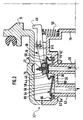
- FIG. 1 shows a fuel tank 10 for a motor vehicle comprising an upper partition 12 and a filling tube 14, the filling orifice 16 of which can be closed by a tight plug (not shown) which cooperates with a seal 18.
- the device for filling and ventilating the tank 10 also comprises a vent pipe 20, also called degassing pipe, which enters an expansion capacity 22 of the fuel volume, arranged at the upper internal part. tank 10.
- a vent pipe 20 also called degassing pipe, which enters an expansion capacity 22 of the fuel volume, arranged at the upper internal part. tank 10.
- the filling device also comprises a discharge conduit 23 opening on the one hand, in the upper part of the filling tube and, on the other hand, in the tank 10 at a level 26 corresponding to the maximum level of fuel 28 when the tank is filled.
- This conduit 23 allows during filling to evacuate the gases contained in the tank 10.
- the upper end 30 of the vent pipe 20 opens into a housing 32, made integrally with the upper part of the filling pipe 14, and the inside 34 of which communicates with the inside of the pipe filling 14.
- the lower rigid partition 36 of the housing 32 into which the upper end 30 of the vent pipe 20 opens has a lever 38 which is pivotally mounted about an axis XX and of which a free end 40 carries a valve d seal 42, produced in the form of an annular bead of elastically deformable material which cooperates with a valve seat 44 formed by the annular radial face of the upper end 30 of the conduit 20.
- the other end 46 of the lever 38 is a heel with the upper face 48 of which is capable of cooperating a portion of the filling plug when the latter is fixed on the filling orifice 16, and this in order to bias the lever 38 in pivoting around the axis XX, clockwise when considering FIG. 1, against a return spring 50 which urges the valve towards its closed position illustrated in FIG. 1.
- the venting duct 20 is closed by the valve 42 which makes it possible to provide the expansion capacity 22 during the filling.
- valve 42 When the user puts the cap back in place, it causes the valve 42 to open by tilting around the axis XX and the communication of the end upper 30 of the vent pipe 20 with the filling pipe 14 is restored.
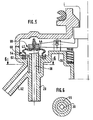
- the rigid lower partition 36 of the housing 32 which is produced by molding in plastic material with a part of the filling tube 14, comprises a vent tube 52 whose upper end 54 opens into the lower rigid partition 36 and whose other end (not shown) is connected to a fuel vapor filtration device (not shown).
- the open air ducts 20 and tubing 52 open into an intermediate open air chamber 56 which is delimited on the one hand by the internal face 58 of the lower rigid partition 36 and, on the other hand , by a flexible waterproofing membrane 60.
- the flexible membrane has a peripheral edge 62 which is mounted clamped in a complementary groove 64 formed in the internal face 58 of the rigid partition 36 in which it is kept compressed by an elastically deformable blade 66 produced integrally with the rigid partition 36.
- the central portion 68 of the flexible sealing membrane 60 which extends opposite the upper end 30 of the vent pipe 20 comprises, on its internal face 70, the bead of seal 42 which cooperates with the annular seal seat 44.
- the bead 42 is made integrally with the flexible membrane of elastomeric material 60, as well as a hooking button 72 which is formed on the external face 74 of the central portion 68 of the membrane flexible seal 60 and which is fitted elastically into a housing 76 formed in the free end 40 of the control lever 38.
- the valve 42 is thus connected to the control lever 38.
- the membrane 60 In order to give the membrane 60 great flexibility, it has in its central portion a fold 78 and a sleeve 80.
- the upper end 30 of the venting duct 20 communicates, through the intermediate venting chamber 56 with the end 54 of the tube 52 of venting.
- the fuel vapors which rise from the tank via the vent pipe 20 are thus completely isolated from the filling pipe 14 and are directed to the device for filtering the fuel vapors.
- the central portion 68 includes an accordion bellows portion 82 which makes it possible to further improve the elastic deformation faculties of the membrane 60 in its central functional area comprising the closure valve.
- the flexible membrane 60 is of reduced dimensions, and this is due to the fact that the ends 30 and 54 of the duct 20 and tube 52 for venting are coaxial.
- the arrangement of the two ends is obtained, directly from molding, by providing that the tube 52 is arranged transversely relative to the conduit 20 and that it opens into an annular channel 55 which surrounds the upper end 30 of the setting conduit. open air 20.
- valve control member 42 is constituted by an arm 138 which is slidably mounted in the lower rigid partition 36.
- the duct 20 and the vent tube 52 are connected at their ends 30 and 54 which open into the chamber 56, the latter being arranged here on the external face 59 of the rigid partition 36, through passages 84 and 86 formed in the rigid upper partition 37 of the housing 32.
- the passage 84 connects the conduit 20 to its end portion 30 and it is surrounded by the passage 86 which connects the conduit 52 to its end portion 54.
- the ends 30 and 54 open coaxially into the lower face 59 of the lower rigid partition 36.
- FIG. 7 The operation of the embodiment illustrated in FIG. 7 is identical to that of the preceding embodiments, the closure of the valve being caused when the user removes the plug 19, the control arm 138 being resiliently biased by the return spring 50 sliding, upwards considering figure 7.
- the flexible sealing membrane independently of the valve 42, the membrane then being in the form of a transverse partition which connects the upper and lower rigid partitions of the housing 32 and which surrounds part of the lever 38 or the sliding arm 138.
- the central portion of the elastic membrane crossed by the arm or the lever can constitute the elastic return means of the latter.
Landscapes
- Engineering & Computer Science (AREA)
- Life Sciences & Earth Sciences (AREA)
- Sustainable Development (AREA)
- Sustainable Energy (AREA)
- Chemical & Material Sciences (AREA)
- Combustion & Propulsion (AREA)
- Transportation (AREA)
- Mechanical Engineering (AREA)
- Cooling, Air Intake And Gas Exhaust, And Fuel Tank Arrangements In Propulsion Units (AREA)
- Self-Closing Valves And Venting Or Aerating Valves (AREA)
Claims (13)
- Einfüll- und Belüftungsvorrichtung für einen Benzintank (10) der Bauart mit einem Rohrstutzen (14) zum Befüllen des Tanks, dessen Einfüllöffnung (16) mit einem Deckel versehen ist, mit einem Rohr (20) zur Abgabe an die Atmosphäre, von dem ein Ende (24) im Inneren des Tanks vorgesehen ist und mit einem Ventil (42, 44), das mit dem anderen Ende (30) des Rohrs zur Abgabe an die Atmosphäre zusammenwirkt und das von dem Deckel gesteuert wird, um das andere Ende (30) des Rohrs zur Abgabe an die Atmosphäre (20) zu verschließen, wenn der Deckel entfernt wird, um ein Ausdehnungsvolumen (22) am oberen Teil des Tanks (10) zu ermöglichen, das von der oberen Wand (12) und der maximalen Einfüllhöhe (26) eingegrenzt wird, wobei das andere Ende (30) des Rohrs (20) zur Abgabe an die Atmosphäre in eine Kammer (56) mündet, die gegen den Rohrstutzen zum Einfüllen (14) in dichter Weise getrennt ist und mit einer Röhre (52) zur Abgabe an die Atmosphäre, die die Kammer (56) mit einer Vorrichtung zum Filtrieren der Benzindämpfe verbindet,
dadurch gekennzeichnet, daß die Kammer (56) teilweise von einer elastischen Membran zum Abdichten (60) eingegrenzt wird. - Vorrichtung nach Anspruch 1, dadurch gekennzeichnet, daß der Abschnitt (68) der elastischen Membran, der sich gegenüber dem anderen Ende (30) des Rohrs (20) zur Abgabe an die Atmosphäre erstreckt, auf seiner Innenseite (70) das Ventil (42) trägt.
- Vorrichtung nach Anspruch 2, dadurch gekennzeichnet, daß die Außenseite des Abschnitts (68) der elastischen Membran zum Abdichten (60) an einen Mechanismus (38) zur Steuerung der Bewegungen des Ventils angeschlossen ist.
- Vorrichtung nach Anspruch 3, dadurch gekennzeichnet, daß der Steuermechanismus wenigstens einen Steuerarm (38, 138) umfaßt, dessen freies Ende (40) mit der Außenseite (74) des Abschnitts (68) der elastischen Membran zum Abdichten (60) verbunden ist.
- Vorrichtung nach Anspruch 4, dadurch gekennzeichnet, daß die Außenseite (74) des Abschnitts (68) der elastischen Membran zum Abdichten einen aus dem gleichen Material gefertigten Anhängeknopf (72) umfaßt, der elastisch in ein komplementäres Lager (76) eingesteckt wird, das am freien Ende (40) des Steuerarms (38, 138) ausgebildet ist.
- Vorrichtung nach einem der Ansprüche 1 bis 5, dadurch gekennzeichnet, daß die Kammer (56) auch von einer starren Wand (76) eingegrenzt wird, in die das andere Ende (30) des Rohrs (20) zur Abgabe an die Atmosphäre und ein Ende (54) der Röhre (52) zur Abgabe an die Atmosphäre münden.
- Vorrichtung nach Anspruch 6, dadurch gekennzeichnet, daß die Enden (30, 54) des Rohrs (20) und der Röhre (52) zur Abgabe an die Atmosphäre, die in die starre Wand (36) münden, nebeneinander liegen.
- Vorrichtung nach Anspruch 6, dadurch gekennzeichnet, daß die Enden (30, 54) des Rohrs (20) und der Röhre (52) zur Abgabe an die Atmosphäre, die in die starre Wand (36) münden, koaxial sind.
- Vorrichtung nach einen der Ansprüche 6 bis 8, im Zusammenhang mit einem der Ansprüche 4 oder 5, dadurch gekennzeichnet, daß der Steuerarm (38, 138) beweglich in Bezug zur starren Wand (36) montiert ist.
- Vorrichtung nach Anspruch 9, dadurch gekennzeichnet, daß der bewegliche Arm (38) auf der starren Wand (36) angelenkt ist.
- Vorrichtung nach Anspruch 9, dadurch gekennzeichnet, daß der Steuerarm (138) verschiebbar in Bezug zur starren Wand (36) montiert ist.
- Vorrichtung nach einem der Ansprüche 6 bis 11, dadurch gekennzeichnet, daß die elastische Membran zum Abdichten (60) einen in Umfangsrichtung verlaufenden Rand (62) umfaßt, der in dichter Weise in eine Vertiefung (64), die in der starren Wand (36) ausgebildet ist, montiert ist.
- Vorrichtung nach einem der Ansprüche 1 bis 12, dadurch gekennzeichnet, daß der Abschnitt (68) der elastischen Membran, der sich gegenüber vom anderen Ende (30) des Rohrs zum Entlüften (20) erstreckt, auf seiner Innenseite (70) einen aus einem Stück zusammen mit der Membran (60) geformten ringförmigen Wulst zum Abdichten (42) umfaßt, der mit einem rinförmigen Sitz zum Abdichten (44) zusammenwirkt, der am anderen Ende (30) des Rohrs zur Abgabe an die Atmosphäre (20) ausgebildet ist.
Applications Claiming Priority (2)
| Application Number | Priority Date | Filing Date | Title |
|---|---|---|---|
| FR9215637A FR2699462B1 (fr) | 1992-12-23 | 1992-12-23 | Dispositif de remplissage et d'aération d'un réservoir de carburant. |
| FR9215637 | 1992-12-23 |
Publications (2)
| Publication Number | Publication Date |
|---|---|
| EP0604321A1 EP0604321A1 (de) | 1994-06-29 |
| EP0604321B1 true EP0604321B1 (de) | 1996-07-17 |
Family
ID=9437050
Family Applications (1)
| Application Number | Title | Priority Date | Filing Date |
|---|---|---|---|
| EP19930403160 Expired - Lifetime EP0604321B1 (de) | 1992-12-23 | 1993-12-23 | Einfüll- und Belüftungsvorrichtung für einen Benzintank |
Country Status (4)
| Country | Link |
|---|---|
| EP (1) | EP0604321B1 (de) |
| DE (1) | DE69303699T2 (de) |
| ES (1) | ES2089762T3 (de) |
| FR (1) | FR2699462B1 (de) |
Family Cites Families (3)
| Publication number | Priority date | Publication date | Assignee | Title |
|---|---|---|---|---|
| FR2628369B1 (fr) * | 1988-03-08 | 1991-09-13 | Journee Paul Sa | Dispositif de mise a l'air libre et de securite contre le remplissage excessif pour reservoir |
| DE3811438A1 (de) * | 1988-04-05 | 1989-10-19 | Kayser A Gmbh & Co Kg | Ventil |
| JPH0612987Y2 (ja) * | 1988-06-06 | 1994-04-06 | 本田技研工業株式会社 | 燃料タンク |
-
1992
- 1992-12-23 FR FR9215637A patent/FR2699462B1/fr not_active Expired - Fee Related
-
1993
- 1993-12-23 EP EP19930403160 patent/EP0604321B1/de not_active Expired - Lifetime
- 1993-12-23 DE DE1993603699 patent/DE69303699T2/de not_active Expired - Fee Related
- 1993-12-23 ES ES93403160T patent/ES2089762T3/es not_active Expired - Lifetime
Also Published As
| Publication number | Publication date |
|---|---|
| FR2699462B1 (fr) | 1995-03-10 |
| DE69303699D1 (de) | 1996-08-22 |
| ES2089762T3 (es) | 1996-10-01 |
| DE69303699T2 (de) | 1996-11-28 |
| EP0604321A1 (de) | 1994-06-29 |
| FR2699462A1 (fr) | 1994-06-24 |
Similar Documents
| Publication | Publication Date | Title |
|---|---|---|
| CA2178573C (fr) | Ensemble robinet/detendeur pour bouteille de gaz et bouteille de gaz equipee d'un tel ensemble | |
| CA2337219A1 (en) | Filler neck closure assembly | |
| EP1133362B1 (de) | Verbindungsvorrichtung für eine pumpe | |
| FR2774951A1 (fr) | Reservoir a carburant muni d'un systeme d'evacuation des gaz | |
| EP0952376A1 (de) | Doppelsitzventil mit aufblasbarer Membran | |
| EP0669222B1 (de) | Höhenverstellbare Armlehne für Kraftfahrzeuge | |
| FR2753138A1 (fr) | Dispositif de remplissage d'un reservoir de carburant de vehicule automobile comportant des moyens de tarage de la pression de gaz | |
| EP0604321B1 (de) | Einfüll- und Belüftungsvorrichtung für einen Benzintank | |
| EP1688332B1 (de) | Pneumatischer Kraftverstärker mit versetzten Ventilsitzen, die von zwei ineinander gleitenden Hülsen getragen werden | |
| EP0459866B1 (de) | Einrichtung für den Belüftungskreislauf eines Kraftstofftanks | |
| EP0774372B1 (de) | Verbesserte Tankentlüftungsvorrichtung für Kraftfahrzeugtank und Kraftfahrzeugtank mit dieser Vorrichtung | |
| EP0604320B1 (de) | Anordnung zum Füllen eines Behälters mit einer Kraftstoffdampffiltervorrichtung | |
| EP0516528B1 (de) | Sicherheitsventil für den Entlüftungskreislauf eines Kfz-Kraftstoffbehälters | |
| FR2625284A1 (fr) | Valve de regulation de la pression a l'interieur d'un reservoir de carburant | |
| EP0064427B1 (de) | Druckregulierventil | |
| FR2676103A3 (fr) | Ressort pneumatique de longueur reglable. | |
| EP0728088B1 (de) | Pneumatischer servomotor mit geräuschlosem betrieb | |
| FR2762807A1 (fr) | Embout de fermeture pour tubulure de remplissage d'un reservoir de carburant d'un vehicule automobile | |
| FR2669864A1 (fr) | Clapet de ventilation pour un reservoir de carburant d'un vehicule. | |
| EP0524882B1 (de) | Verschlussdeckel mit einem Überdruckventil | |
| EP0116796B1 (de) | Diebessichere Kappe, insbesondere für Brennstofftanks von Fahrzeugen | |
| EP0774569B1 (de) | Verschlussdeckel für einen Kühlungskreislauf eines Kraftfahrzeuges | |
| FR2675570A1 (fr) | Dispositif de securite pour un bouchon de fermeture d'un echangeur thermique. | |
| FR2915786A1 (fr) | Raccord de type bloqueur a clapet et purge | |
| FR2722833A1 (fr) | Circuit de refroidissement de moteur a remplissage rapide |
Legal Events
| Date | Code | Title | Description |
|---|---|---|---|
| PUAI | Public reference made under article 153(3) epc to a published international application that has entered the european phase |
Free format text: ORIGINAL CODE: 0009012 |
|
| AK | Designated contracting states |
Kind code of ref document: A1 Designated state(s): DE ES GB IT |
|
| 17P | Request for examination filed |
Effective date: 19941028 |
|
| 17Q | First examination report despatched |
Effective date: 19951004 |
|
| GRAG | Despatch of communication of intention to grant |
Free format text: ORIGINAL CODE: EPIDOS AGRA |
|
| GRAH | Despatch of communication of intention to grant a patent |
Free format text: ORIGINAL CODE: EPIDOS IGRA |
|
| GRAH | Despatch of communication of intention to grant a patent |
Free format text: ORIGINAL CODE: EPIDOS IGRA |
|
| GRAA | (expected) grant |
Free format text: ORIGINAL CODE: 0009210 |
|
| AK | Designated contracting states |
Kind code of ref document: B1 Designated state(s): DE ES GB IT |
|
| REF | Corresponds to: |
Ref document number: 69303699 Country of ref document: DE Date of ref document: 19960822 |
|
| REG | Reference to a national code |
Ref country code: ES Ref legal event code: FG2A Ref document number: 2089762 Country of ref document: ES Kind code of ref document: T3 |
|
| ITF | It: translation for a ep patent filed |
Owner name: SOCIETA' ITALIANA BREVETTI S.P.A. |
|
| GBT | Gb: translation of ep patent filed (gb section 77(6)(a)/1977) |
Effective date: 19960923 |
|
| REG | Reference to a national code |
Ref country code: ES Ref legal event code: FG2A Ref document number: 2089762 Country of ref document: ES Kind code of ref document: T3 |
|
| PLBE | No opposition filed within time limit |
Free format text: ORIGINAL CODE: 0009261 |
|
| STAA | Information on the status of an ep patent application or granted ep patent |
Free format text: STATUS: NO OPPOSITION FILED WITHIN TIME LIMIT |
|
| 26N | No opposition filed | ||
| REG | Reference to a national code |
Ref country code: GB Ref legal event code: IF02 |
|
| PGFP | Annual fee paid to national office [announced via postgrant information from national office to epo] |
Ref country code: ES Payment date: 20081226 Year of fee payment: 16 |
|
| PGFP | Annual fee paid to national office [announced via postgrant information from national office to epo] |
Ref country code: DE Payment date: 20090202 Year of fee payment: 16 |
|
| PGFP | Annual fee paid to national office [announced via postgrant information from national office to epo] |
Ref country code: GB Payment date: 20081229 Year of fee payment: 16 |
|
| PGFP | Annual fee paid to national office [announced via postgrant information from national office to epo] |
Ref country code: IT Payment date: 20081229 Year of fee payment: 16 |
|
| GBPC | Gb: european patent ceased through non-payment of renewal fee |
Effective date: 20091223 |
|
| PG25 | Lapsed in a contracting state [announced via postgrant information from national office to epo] |
Ref country code: DE Free format text: LAPSE BECAUSE OF NON-PAYMENT OF DUE FEES Effective date: 20100701 |
|
| PG25 | Lapsed in a contracting state [announced via postgrant information from national office to epo] |
Ref country code: GB Free format text: LAPSE BECAUSE OF NON-PAYMENT OF DUE FEES Effective date: 20091223 |
|
| REG | Reference to a national code |
Ref country code: ES Ref legal event code: FD2A Effective date: 20110310 |
|
| PG25 | Lapsed in a contracting state [announced via postgrant information from national office to epo] |
Ref country code: IT Free format text: LAPSE BECAUSE OF NON-PAYMENT OF DUE FEES Effective date: 20091223 |
|
| PG25 | Lapsed in a contracting state [announced via postgrant information from national office to epo] |
Ref country code: ES Free format text: LAPSE BECAUSE OF NON-PAYMENT OF DUE FEES Effective date: 20110309 |
|
| PG25 | Lapsed in a contracting state [announced via postgrant information from national office to epo] |
Ref country code: ES Free format text: LAPSE BECAUSE OF NON-PAYMENT OF DUE FEES Effective date: 20091224 |