EP0603796A2 - Flame starting system for internal combustion device - Google Patents
Flame starting system for internal combustion device Download PDFInfo
- Publication number
- EP0603796A2 EP0603796A2 EP93120531A EP93120531A EP0603796A2 EP 0603796 A2 EP0603796 A2 EP 0603796A2 EP 93120531 A EP93120531 A EP 93120531A EP 93120531 A EP93120531 A EP 93120531A EP 0603796 A2 EP0603796 A2 EP 0603796A2
- Authority
- EP
- European Patent Office
- Prior art keywords
- flame
- start system
- glow plug
- glow
- monitoring device
- Prior art date
- Legal status (The legal status is an assumption and is not a legal conclusion. Google has not performed a legal analysis and makes no representation as to the accuracy of the status listed.)
- Granted
Links
- 238000002485 combustion reaction Methods 0.000 title claims abstract description 29
- 239000000446 fuel Substances 0.000 claims abstract description 23
- 238000012806 monitoring device Methods 0.000 claims abstract description 14
- 238000010438 heat treatment Methods 0.000 claims description 26
- 238000012544 monitoring process Methods 0.000 claims description 18
- 230000006870 function Effects 0.000 claims description 8
- 230000001105 regulatory effect Effects 0.000 claims description 8
- 230000015572 biosynthetic process Effects 0.000 claims description 4
- 230000001276 controlling effect Effects 0.000 claims description 2
- 230000007257 malfunction Effects 0.000 abstract description 4
- 239000003570 air Substances 0.000 description 23
- 239000000498 cooling water Substances 0.000 description 5
- 238000005259 measurement Methods 0.000 description 4
- OKKJLVBELUTLKV-UHFFFAOYSA-N Methanol Chemical compound OC OKKJLVBELUTLKV-UHFFFAOYSA-N 0.000 description 3
- 239000000463 material Substances 0.000 description 3
- LFQSCWFLJHTTHZ-UHFFFAOYSA-N Ethanol Chemical compound CCO LFQSCWFLJHTTHZ-UHFFFAOYSA-N 0.000 description 2
- XEEYBQQBJWHFJM-UHFFFAOYSA-N Iron Chemical compound [Fe] XEEYBQQBJWHFJM-UHFFFAOYSA-N 0.000 description 2
- PXHVJJICTQNCMI-UHFFFAOYSA-N Nickel Chemical compound [Ni] PXHVJJICTQNCMI-UHFFFAOYSA-N 0.000 description 2
- 230000006378 damage Effects 0.000 description 2
- 230000001419 dependent effect Effects 0.000 description 2
- 238000001514 detection method Methods 0.000 description 2
- 238000010586 diagram Methods 0.000 description 2
- 238000002347 injection Methods 0.000 description 2
- 239000007924 injection Substances 0.000 description 2
- 239000000203 mixture Substances 0.000 description 2
- 230000003287 optical effect Effects 0.000 description 2
- 238000013021 overheating Methods 0.000 description 2
- 238000012546 transfer Methods 0.000 description 2
- 229910003321 CoFe Inorganic materials 0.000 description 1
- 239000012080 ambient air Substances 0.000 description 1
- 238000007664 blowing Methods 0.000 description 1
- 239000000919 ceramic Substances 0.000 description 1
- 238000001816 cooling Methods 0.000 description 1
- 238000013461 design Methods 0.000 description 1
- 230000005611 electricity Effects 0.000 description 1
- 239000003344 environmental pollutant Substances 0.000 description 1
- 238000007689 inspection Methods 0.000 description 1
- 239000011810 insulating material Substances 0.000 description 1
- 238000009413 insulation Methods 0.000 description 1
- 229910052742 iron Inorganic materials 0.000 description 1
- 229910052759 nickel Inorganic materials 0.000 description 1
- 231100000719 pollutant Toxicity 0.000 description 1
- 239000004065 semiconductor Substances 0.000 description 1
- 238000003466 welding Methods 0.000 description 1
Images


Classifications
-
- F—MECHANICAL ENGINEERING; LIGHTING; HEATING; WEAPONS; BLASTING
- F02—COMBUSTION ENGINES; HOT-GAS OR COMBUSTION-PRODUCT ENGINE PLANTS
- F02N—STARTING OF COMBUSTION ENGINES; STARTING AIDS FOR SUCH ENGINES, NOT OTHERWISE PROVIDED FOR
- F02N19/00—Starting aids for combustion engines, not otherwise provided for
- F02N19/02—Aiding engine start by thermal means, e.g. using lighted wicks
- F02N19/04—Aiding engine start by thermal means, e.g. using lighted wicks by heating of fluids used in engines
- F02N19/06—Aiding engine start by thermal means, e.g. using lighted wicks by heating of fluids used in engines by heating of combustion-air by flame generating means, e.g. flame glow-plugs
-
- F—MECHANICAL ENGINEERING; LIGHTING; HEATING; WEAPONS; BLASTING
- F02—COMBUSTION ENGINES; HOT-GAS OR COMBUSTION-PRODUCT ENGINE PLANTS
- F02B—INTERNAL-COMBUSTION PISTON ENGINES; COMBUSTION ENGINES IN GENERAL
- F02B3/00—Engines characterised by air compression and subsequent fuel addition
- F02B3/06—Engines characterised by air compression and subsequent fuel addition with compression ignition
-
- Y—GENERAL TAGGING OF NEW TECHNOLOGICAL DEVELOPMENTS; GENERAL TAGGING OF CROSS-SECTIONAL TECHNOLOGIES SPANNING OVER SEVERAL SECTIONS OF THE IPC; TECHNICAL SUBJECTS COVERED BY FORMER USPC CROSS-REFERENCE ART COLLECTIONS [XRACs] AND DIGESTS
- Y02—TECHNOLOGIES OR APPLICATIONS FOR MITIGATION OR ADAPTATION AGAINST CLIMATE CHANGE
- Y02T—CLIMATE CHANGE MITIGATION TECHNOLOGIES RELATED TO TRANSPORTATION
- Y02T10/00—Road transport of goods or passengers
- Y02T10/10—Internal combustion engine [ICE] based vehicles
- Y02T10/12—Improving ICE efficiencies
Definitions
- the invention relates to a flame start system for a combustion device, in particular an internal combustion engine for preheating the combustion air with a flame glow plug which is arranged in the intake air duct of the combustion device, fuel and power supply devices for the flame glow plug and a control or regulating device for controlling or regulating the fuel and power supply the flame glow plug.
- Such a flame start system is used in particular to enable a cold start of internal combustion engines such as diesel engines, gasoline engines, methanol and ethanol engines with and without charge air and of evaporator burners. It is used in particular in diesel engines such as, for example, direct-injection diesel engines for use in trucks, in order to ensure that the engine starts safely at low temperatures, for example below -10 ° C.
- the object on which the invention is based is therefore to design the flame start system of the type mentioned at the outset in such a way that its proper functioning can be guaranteed at all times.
- This object is achieved according to the invention by a monitoring device which monitors the function of the flame start system and reports functional errors that occur.
- the flame start system according to the invention is thus designed in such a way that it is monitored for its perfect functioning and is subjected to a functional check in order to enable the combustion device, in particular the associated internal combustion engine, to start safely and, if necessary, to initiate appropriate measures if a malfunction is detected and displayed in good time.
- a flame start system comprises at least one flame glow plug FGK1 ... n, which is arranged in the manner shown in Fig. 2 in the air intake duct of a combustion device, in particular an internal combustion engine, fuel and power supply devices MV1 ... n and S1 for the flame glow plug FGK1 ... n and a control device A1, via which the fuel and power supply of the flame glow plug FGK1 ... n is controlled.
- the control device A1 is connected to a monitoring device A2, on which the output signals of a glow element monitoring sensor C1 and a flame monitoring sensor C2 are connected.
- the monitoring device A2 is connected to a display device A3 for displaying the monitoring result.
- the display can e.g. as a light signal or on a scoreboard.
- An air speed sensor C3 is also provided, which determines the air speed or the air flow rate in the intake air duct and sends a corresponding signal to the monitoring device A2, which then operates the control device A1 in such a way that the flame glow plugs FGK1 ... n are supplied with a quantity of fuel which corresponds to the air speed or amount of air in the air intake duct.
- Temperature sensors B1 ... n are used to determine the outside temperature or the cooling water temperature and are connected to the control device A1.
- the electrical energy supply S1 is switched on by closing the switch, for example the ignition lock switch, then the control device A1 of the system is activated.
- the cooling water temperature or the ambient air temperature is queried via the temperature sensors B1 ... n, when this temperature falls below a certain value, the control device A1 supplies the glow elements of the flame glow plugs FGK1 ... n with current.
- Flame start systems therefore also serve to reduce the pollutant content of the exhaust gas after the start of an internal combustion engine.
- temperature-dependent resistors with a positive or negative temperature coefficient are used. If the control device A1 has a cold engine, for example a cooling water temperature below 60 ° C. and an ambient temperature of, for example determines below 20 ° C, then the glow elements of the flame glow plugs are switched through, for example via semiconductor switching elements, ie they are supplied with current.
- the flame start system is to be used every time the engine is started, the measurement of the cooling water and / or ambient temperature can also be dispensed with.
- the function of the flame glow plug in particular of its glow element or heating element, is controlled by the glow element monitoring sensor C1.
- the fuel delivery pump MV1 ... n is switched on.
- the delivery rate is preferably dependent on the cycle frequency of the control, a constant amount of fuel being delivered per working stroke and the cycle frequency via the air speed sensor C3, i.e. is regulated via the air speed prevailing in the air intake duct. Continuously delivering fuel pumps with appropriate control can also be used.
- the ignition and the flame are controlled by the flame monitoring sensor C2.
- the incoming sensor signals are logically linked in the monitoring device A2 so that in the event of malfunctions or failures of a flame glow plug FGK1 ... n these can be displayed on the display A3. If a flame glow plug FGK1 ... n does not ignite, a repeated start can also be initiated by control device A1 if no functional errors are detected.
- the detected functional errors are either shown optically on the display A3 and / or stored in an error memory which can be read out.
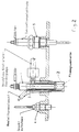
- FIG. 2 shows a flame glow plug 1 and a jacket thermocouple 3 as a glow element monitoring sensor and a ionization electrode 5 as a flame monitoring sensor shown.
- the glow element 2 of the flame glow plug 1 consists e.g. from a ceramic heating element and preferably from one with an insulating material, e.g. MgO-filled glow tube made of scale-free material, in which at least one heating coil with high specific resistance and little change in resistance over temperature (maximum 3 to 5%) and at least one control coil made of a material with a positive temperature coefficient are embedded.
- the heating coil sits in the tip of the heating rod, while the control coil is connected in series with the heating coil.
- Glow element monitoring is possible by detecting the temperature of the glow element, for which there are several options.
- thermocouples that are integrated in the flame glow plug.
- Sheathed thermocouples which are embedded in a shell made of scale-free material, are particularly suitable for this purpose. These sheathed thermocouples should be at a convenient location on the glow element, i.e. at the hottest point, and have no electrical contact with the glow element. Good thermal contact with the glow element should be ensured. This can be achieved by a welded connection of the jacket of the jacket thermocouple to the glow tube of the glow element.
- thermocouple 3 An example of such a jacket thermocouple 3 is shown in FIG. 2.
- the thermocouple 3 is guided to the rear through the body of the flame glow plug 1 and connected to the control device A1 via a cable.
- the control coil being connected in series with the heating coil and having a positive temperature coefficient (for example made of nickel, iron, CoFe) can also have a Resistance measurement can be concluded on the temperature of the glow element. Both the total resistance and the individual resistances are queried, for example via a tap at the welding point between the control coil and the heating coil, the resistance curve of the control coil being recorded.
- a positive temperature coefficient for example made of nickel, iron, CoFe
- the glow element is initially heated with a duty cycle of 100%. If there is no temperature increase within a certain period of time via the thermocouple or a resistance measurement, e.g. 10 seconds can be determined, it is concluded that the glow element has failed. As soon as it is determined that the actual temperature is equal to the target temperature, the glow element is supplied with current in a clocked manner and is regulated to the target temperature according to a P, PI, PID, two-point or multi-point control algorithm. The cycle ratio is between 0 and 100% of the duty cycle.
- the glow element must not be subjected to heating powers that lead to the destruction of the heating or control coil. This can be the case, in particular, if the heating rod is strongly cooled externally by strong intake air movements, for example in engine operation or by non-ignited fuel.
- the thermocouple 3 which is welded to the outside of the glow tube, will indicate a temperature which is too low and will attempt to counteract this by increasing the cycle ratio. This results in an increase in the heating output.
- the control coil with a positive temperature coefficient will decrease in resistance and allow an increased current flow through the heating and control coils. This takes the Spiral resistance.
- the heating output is therefore limited to a maximum value at which the heating and control filaments cannot be damaged.
- the fuel supply is switched on by the control device A1.
- the amount of fuel required is calculated using an air volume measurement.
- the ignition and the flame of the flame glow plug are checked via the flame monitoring sensor C1.
- ionization electrodes that can indicate a flame.
- Such ionization electrodes can either be integrated into the flame glow plugs FGK1 ... n or installed on the intake tract of the internal combustion engine, as shown in FIG. 2. If the ionization electrodes on the intake tract are installed at a certain distance from the flame glow plugs FGK1 ... n, which corresponds to the minimum flame width with optimal combustion of the air / fuel mixture, then a statement can be made about the condition of the flame glow plugs FGK1 ... n, as with worse Mixture formation this minimum flame width is not reached.
- Bimetallic strips that trigger electrical contacts when heated by the flame but also sensor elements with positive and negative temperature coefficients, the resistance of which depends on the temperature, are suitable as sensors.
- thermocouples that indicate the temperature increase due to the flame, as well as optical sensors be used, which react to the light exposure of the flame.
- FIG. 2 An example of a flame monitoring sensor in the form of an ionization electrode 5 is shown in detail in FIG. 2.
- the ionization electrode 5 is attached at a selected distance from the flame glow plug 1 in the intake tract of the internal combustion engine. It shows the control device A1 whether sufficient flame formation is taking place.
- the distance of the ionization electrode 5 from the flame glow plug 1 should be selected so that it corresponds to the minimum flame width. In extreme cases, if the flame only burns inside the flame glow plug, it may also make sense to provide the ionization electrode directly integrated in the flame glow plug.
- the flame is detected in order to postpone a flame arrest, in particular at higher air speeds in engine operation, up to the highest possible load and speed point. With increasing air speed, the flame width is reduced due to the high excess of air. This can be counteracted by increasing the fuel supply to match the air volume and, analogously, the power supply to the flame glow plug. If a flame arrives anyway, suitable measures are taken by the control device to initiate an immediate new ignition. For this purpose, the glow temperature is queried via the thermocouple in order to increase the heating power at too low a temperature due to cooling by cold blowing at higher air speeds or by non-evaporated fuel until a sufficient ignition temperature is reached. It may also be advantageous not to supply fuel at times to make heating up easier. The fuel pump is then switched on in order to correspond to the signal from the air sensor 4 of the flame glow plug 1 supply fuel until the ionization electrode 5 emits a flame signal.
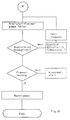
- Fig. 3a shows that after switching on the switch S1 it is determined whether the operating temperature is below 60 ° C. If this is the case, the glow element is heated with a duty cycle of 100% until the ignition temperature of the flame glow plug, e.g. 950 ° C is reached. Then the flame glow plug is supplied with electricity in a clocked manner and regulated to a temperature equal to 950 ° C.
- 3b shows the timing of the fuel delivery pump as a function of the absolute pressure in the intake tract via a corresponding actuation clock frequency, which is determined in accordance with a stored fuel absolute pressure map.
- the downstream flame detection leads to negative Result for a repeat start, while if the result is positive, the after-flame operation is switched over.
- a function check is therefore carried out, which includes a function check of the glow element and flame detection. This makes it possible to determine changes over the entire lifespan of the flame start system before they lead to the engine failing to start or cause damage. Such changes are displayed if they exceed or fall below certain limit values. Corresponding measures can also be taken independently via the associated electronic control, which can consist, for example, of an automatic repeat start.
Landscapes
- Engineering & Computer Science (AREA)
- Chemical & Material Sciences (AREA)
- Combustion & Propulsion (AREA)
- Mechanical Engineering (AREA)
- General Engineering & Computer Science (AREA)
- Combined Controls Of Internal Combustion Engines (AREA)
- Control Of Combustion (AREA)
- Ignition Installations For Internal Combustion Engines (AREA)
- Valve Device For Special Equipments (AREA)
- Spray-Type Burners (AREA)
- Regulation And Control Of Combustion (AREA)
- Fluidized-Bed Combustion And Resonant Combustion (AREA)
Abstract
Description
Die Erfindung betrifft eine Flammstartanlage für eine Verbrennungseinrichtung, insbesondere eine Brennkraftmaschine zum Vorvärmen der Verbrennungsluft mit einer Flammglühkerze, die im Ansaugluftkanal der Verbrennungseinrichtung angeordnet ist, Kraftstoff- und Stromversorgungseinrichtungen für die Flammglühkerze und einer Steuer- oder Regeleinrichtung zum Steuern oder Regeln der Kraftstoff- und Stromversorgung der Flammglühkerze.The invention relates to a flame start system for a combustion device, in particular an internal combustion engine for preheating the combustion air with a flame glow plug which is arranged in the intake air duct of the combustion device, fuel and power supply devices for the flame glow plug and a control or regulating device for controlling or regulating the fuel and power supply the flame glow plug.
Eine derartige Flammstartanlage dient insbesondere dazu, einen Kaltstart von Brennkraftmaschinen wie beispielsweise Dieselmotoren, Ottomotoren, Methanol- und Ethanolmotoren mit und ohne Ladeluft sowie von Verdampferbrennern zu ermöglichen. Sie wird insbesondere bei Dieselmotoren wie beispielsweise direkt einspritzenden Dieselmotoren für den LKW-Einsatz verwendet, um bei tiefen Temperaturen von beispielsweise unter -10°C einen sicheren Start des Motors zu gewährleisten.Such a flame start system is used in particular to enable a cold start of internal combustion engines such as diesel engines, gasoline engines, methanol and ethanol engines with and without charge air and of evaporator burners. It is used in particular in diesel engines such as, for example, direct-injection diesel engines for use in trucks, in order to ensure that the engine starts safely at low temperatures, for example below -10 ° C.
Um einen sicheren Start einer mit einer derartigen Flammstartanlage ausgerüsteteten Verbrennungseinrichtung, insbesondere einer Brennkraftmaschine, zu ermöglichen, ist es allerdings erforderlich, daß die Flammstartanlage fehlerfrei arbeitet. Bei den bisher bekannten Flammstartanlagen führen Fehler in der Funktion dazu, daß die Flammstartanlage als Starthilfe ausfällt und daher ein Starten bei niedrigen Außentemperaturen nicht möglich ist.In order to enable a reliable start of a combustion device equipped with such a flame start system, in particular an internal combustion engine, it is necessary that the flame start system works without errors. In the previously known flame start systems, errors in function lead to the flame start system failing as a starting aid and therefore starting at low outside temperatures is not possible.
Die der Erfindung Zugrundeliegende Aufgabe besteht daher darin, die Flammstartanlage der eingangs genannten Art so auszubilden, daß ihre einwandfreie Funktion jederzeit gewährleistet werden kann.The object on which the invention is based is therefore to design the flame start system of the type mentioned at the outset in such a way that its proper functioning can be guaranteed at all times.
Diese Aufgabe wird gemäß der Erfindung durch eine Überwachungseinrichtung gelöst, die die Funktion der Flammstartanlage überwacht und auftretende Funktionsfehler meldet.This object is achieved according to the invention by a monitoring device which monitors the function of the flame start system and reports functional errors that occur.
Die erfindungsgemäße Flammstartanlage ist somit so ausgebildet, daß sie auf ihre einwandfreie Funktion überwacht wird und einer Funktionskontrolle unterworfen wird, um einen sicheren Start der Verbrennungseinrichtung, insbesondere der Zugehörigen Brennkraftmaschine, zu ermöglichen und ggfs. bei rechtzeitiger Erkennung und Anzeige einer Funktionsstörung entsprechende Maßnahmen einzuleiten.The flame start system according to the invention is thus designed in such a way that it is monitored for its perfect functioning and is subjected to a functional check in order to enable the combustion device, in particular the associated internal combustion engine, to start safely and, if necessary, to initiate appropriate measures if a malfunction is detected and displayed in good time.
Besonders bevorzugte Ausführungsformen der erfindungsgemäßen Flammstartanlage sind Gegenstand der Patentansprüche 2 bis 12.Particularly preferred embodiments of the flame start system according to the invention are the subject of
Im folgenden werden anhand der zugehörigen Zeichnung besonders bevorzugte Ausführungsbeispiele der Erfindung näher beschrieben. Es zeigen
- Fig. 1 ein Ausführungsbeispiel der erfindungsgemäßen Flammstartanlage in einem schematischen Diagramm,
- Fig. 2 die Anordnung der Flammglühkerze und der Überwachungssensoren bei dem in Fig. 1 dargestellten Ausführungsbeispiel und
- Fig. 3a und 3b in einem Flußdiagramm die Arbeitsabfolge bei der in Fig. 1 dargestellten Flammstartanlage.
- 1 shows an embodiment of the flame start system according to the invention in a schematic diagram,
- Fig. 2 shows the arrangement of the flame glow plug and the monitoring sensors in the embodiment shown in Fig. 1 and
- 3a and 3b in a flowchart the work sequence in the flame start system shown in Fig. 1.
Wie es in Fig. 1 dargestellt ist, umfaßt eine Flammstartanlage wenigstens eine Flammglühkerze FGK1...n, die in der in Fig. 2 dargestellten Weise im Luftansaugkanal einer Verbrennungseinrichtung, insbesondere einer Brennkraftmaschine, angeordnet ist, Kraftstoff- und Stromversorgungseinrichtungen MV1...n und S1 für die Flammglühkerze FGK1...n und eine Steuereinrichtung A1, über die die Kraftstoff- und Stromversorgung der Flammglühkerze FGK1...n gesteuert wird.As shown in Fig. 1, a flame start system comprises at least one flame glow plug FGK1 ... n, which is arranged in the manner shown in Fig. 2 in the air intake duct of a combustion device, in particular an internal combustion engine, fuel and power supply devices MV1 ... n and S1 for the flame glow plug FGK1 ... n and a control device A1, via which the fuel and power supply of the flame glow plug FGK1 ... n is controlled.
Die Steuereinrichtung A1 ist mit einer Überwachungseinrichtung A2 verbunden, an der die Ausgangssignale eines Glühelementüberwachungssensors C1 und eines Flammüberwachungssensors C2 liegen. Die Überwachungseinrichtung A2 ist mit einer Anzeigeeinrichtung A3 zum Anzeigen des Überwachungsergebnisses verbunden. Die Anzeige kann z.B. als Lichtsignal oder über eine Anzeigetafel erfolgen.The control device A1 is connected to a monitoring device A2, on which the output signals of a glow element monitoring sensor C1 and a flame monitoring sensor C2 are connected. The monitoring device A2 is connected to a display device A3 for displaying the monitoring result. The display can e.g. as a light signal or on a scoreboard.
Es ist weiterhin ein Luftgeschwindigkeitssensor C3 vorgesehen, der die Luftgeschwindigkeit oder den Luftdurchsatz im Ansaugluftkanal ermittelt und ein entsprechendes Signal an die Überwachungseinrichtung A2 legt, die daraufhin die Steuereinrichtung A1 so betreibt, daß die Flammglühkerzen FGK1...n mit einer Kraftstoffmenge versorgt werden, die der Luftgeschwindigkeit oder Luftmenge im Luftansaugkanal entspricht. Temperatursensoren B1...n dienen zur Ermittlung der Außentemperatur bzw. der Kühlwassertemperatur, und sind mit der Steuereinrichtung A1 verbunden.An air speed sensor C3 is also provided, which determines the air speed or the air flow rate in the intake air duct and sends a corresponding signal to the monitoring device A2, which then operates the control device A1 in such a way that the flame glow plugs FGK1 ... n are supplied with a quantity of fuel which corresponds to the air speed or amount of air in the air intake duct. Temperature sensors B1 ... n are used to determine the outside temperature or the cooling water temperature and are connected to the control device A1.
Wenn bei der in Fig. 1 dargestellten Flammstartanlage die elektrische Energieversorgung S1 durch Schließen des Schalters, beispielsweise des Zündschloßschalters, angeschaltet wird, dann wird die Steuereinrichtung A1 der Anlage aktiviert. Über die Temperatursensoren B1...n wird die Kühlwassertemperatur bzw. die Umgebungslufttemperatur abgefragt, wobei dann, wenn diese Temperatur einen bestimmten Wert unterschreitet, die Steuereinrichtung A1 die Glühelemente der Flammglühkerzen FGK1...n mit Strom versorgt.If, in the flame start system shown in FIG. 1, the electrical energy supply S1 is switched on by closing the switch, for example the ignition lock switch, then the control device A1 of the system is activated. The cooling water temperature or the ambient air temperature is queried via the temperature sensors B1 ... n, when this temperature falls below a certain value, the control device A1 supplies the glow elements of the flame glow plugs FGK1 ... n with current.
In den letzten Jahren sind die Anforderungen an Flammstartanlagen stetig gestiegen. Während bisher derartige Anlagen lediglich bei tiefen Umgebungstemperaturen von beispielsweise -10°C bei direkt einspritzenden Dieselmotoren bis zum Start der Brennkraftmaschine eingesetzt wurden, wobei über bis zu 60 Sekunden vorgeglüht werden mußte, bevor die Flammglühkerze gezündet werden konnte , ist es heutzutage angestrebt, Flammstartanlagen bei jedem Start der Brennkraftmaschine einzusetzen, wobei ein Vorglühen der Flammglühkerze über eine kurze Zeit von beispielsweise weniger als 10 Sekunden möglich sein soll und die Flammstartanlage auch bei laufendem Motor in Betrieb sein soll. Das heißt, daß ein Nachflammen von bis zu ca. 8 Minuten möglich sein soll. Auch in diesem Nachflammbetrieb, d.h. bei laufendem Motor, sollen die Betriebsbedingungen der Flammglühkerzen so gesteuert oder geregelt werden, daß ein Flammabriß oder ein Ausfall der Flammglühkerzen, beispielsweise durch Überhitzung des Glühoder Heizelementes, vermieden wird.In recent years, the requirements for flame start systems have increased steadily. While systems of this type were previously only used at low ambient temperatures of, for example, -10 ° C in the case of direct-injection diesel engines until the internal combustion engine started, which required preheating for up to 60 seconds before the flame glow plug could be ignited, the aim today is to use flame start systems use every start of the internal combustion engine, the preheating of the flame glow plug should be possible for a short time, for example less than 10 seconds, and the flame start system should also be in operation with the engine running. This means that an afterflame of up to approx. 8 minutes should be possible. Also in this post-flame mode, i.e. with the engine running, the operating conditions of the flame glow plugs should be controlled or regulated so that a flame break or failure of the flame glow plugs, for example due to overheating of the glow or heating element, is avoided.
Der Grund für diese Erweiterung des Betriebsbereiches von Flammstartanlagen besteht in der Verschärfung der gesetzlichen Bestimmungen bezüglich der Reinheit des Abgases. Flammstartanlagen dienen somit auch dazu, den Schadstoffgehalt des Abgases nach dem Start einer Brennkraftmaschine herabzusetzen.The reason for this expansion of the operational area of flame start systems is the tightening of the legal regulations regarding the purity of the exhaust gas. Flame start systems therefore also serve to reduce the pollutant content of the exhaust gas after the start of an internal combustion engine.
Als Temperatursensoren B₁...n für die Abfrage der Kühlwasser und/oder Umgebungstemperatur werden temperaturabhängige Widerstände mit positivem oder negativem Temperaturkoeffizienten eingesetzt. Wenn die Steuereinrichtung A1 einen betriebskalten Motor, beispielsweise eine Kühlwassertemperatur unter 60°C sowie eine Umgebungstemperatur von beispielsweise unter 20°C feststellt, dann werden die Glühelemente der Flammglühkerzen, beispielsweise über Halbleiterschaltelemente, durchgeschaltet, d.h. mit Strom versorgt.As temperature sensors B₁ ... n for querying the cooling water and / or ambient temperature, temperature-dependent resistors with a positive or negative temperature coefficient are used. If the control device A1 has a cold engine, for example a cooling water temperature below 60 ° C. and an ambient temperature of, for example determines below 20 ° C, then the glow elements of the flame glow plugs are switched through, for example via semiconductor switching elements, ie they are supplied with current.
Falls die Flammstartanlage bei jedem Start des Motors eingesetzt werden soll, kann auf die Messung der Kühlwasser und/oder Umgebungstemperatur auch verzichtet werden.If the flame start system is to be used every time the engine is started, the measurement of the cooling water and / or ambient temperature can also be dispensed with.
Die Funktion der Flammglühkerze insbesondere ihres Glühelementes oder Heizstabes wird über den Glühelementüberwachungssensor C1 kontrolliert. Sobald der Glühelementüberwachungssensor C1 eine korrekte Funktion des Glühelementes festgestellt hat, wird die Kraftstofförderpumpe MV1...n angeschaltet. Vorzugsweise ist die Fördermenge von der Taktfrequenz der Ansteuerung abhängig, wobei pro Arbeitshub eine konstante Kraftstoffmenge gefördert wird und die Taktfrequenz über den Luftgeschwindigkeitssensor C3, d.h. über die im Luftansaugkanal herrschende Luftgeschwindigkeit, geregelt wird. Es sind auch kontinuierlich fördernde Kraftstoffpumpen mit entsprechender Ansteuerung einsetzbar.The function of the flame glow plug, in particular of its glow element or heating element, is controlled by the glow element monitoring sensor C1. As soon as the glow element monitoring sensor C1 has determined that the glow element is functioning correctly, the fuel delivery pump MV1 ... n is switched on. The delivery rate is preferably dependent on the cycle frequency of the control, a constant amount of fuel being delivered per working stroke and the cycle frequency via the air speed sensor C3, i.e. is regulated via the air speed prevailing in the air intake duct. Continuously delivering fuel pumps with appropriate control can also be used.
Die Entflammung und die Flamme werden durch den Flammüberwachungssensor C2 kontrolliert.The ignition and the flame are controlled by the flame monitoring sensor C2.
In der Überwachungseinrichtung A2 werden die eingehenden Sensorsignale logisch verknüpft, damit bei auftretenden Funktionsfehlern oder Ausfällen einer Flammglühkerze FGK1...n diese an der Anzeige A3 angezeigt werden können. Bei einer Nichtentflammung einer Flammglühkerze FGK1...n kann auch ein wiederholter Start durch die Steuereinrichtung A1 eingeleitet werden, wenn keine Funktionsfehler erkannt werden. Die erkannten Funktionsfehler werden an der Anzeige A3 entweder optisch angezeigt und/oder in einem Fehlerspeicher abgespeichert, der ausgelesen werden kann.The incoming sensor signals are logically linked in the monitoring device A2 so that in the event of malfunctions or failures of a flame glow plug FGK1 ... n these can be displayed on the display A3. If a flame glow plug FGK1 ... n does not ignite, a repeated start can also be initiated by control device A1 if no functional errors are detected. The detected functional errors are either shown optically on the display A3 and / or stored in an error memory which can be read out.
In Fig. 2 sind im einzelnen eine Flammglühkerze 1 sowie ein Mantelthermoelement 3 als Glühelementüberwachungssensor und eine Jonisationselektrode 5 als Flammüberwachungssensor dargestellt.2 shows a
Das Glühelement 2 der Flammglühkerze 1 besteht z.B. aus einem Keramikheizstab und vorzugsweise aus einem mit einem Isolierstoff, z.B. MgO gefüllten Glührohr aus zunderfreiem Material, in dem wenigstens eine Heizwendel mit hohem spezifischem Widerstand und geringer Änderung des Widerstandes über die Temperatur (maximal 3 bis 5 %) sowie wenigstens eine Regelwendel aus einem Material mit einem positiven Temperaturkoeffizienten eingebettet sind. Die Heizwendel sitzt in der Spitze des Heizstabes, während die Regelwendel in Reihe zur Heizwendel geschaltet ist.The
Die Glühelementüberwachung ist durch eine Erfassung der Temperatur des Glühelementes möglich, wofür es mehrere Möglichkeiten gibt.Glow element monitoring is possible by detecting the temperature of the glow element, for which there are several options.
Eine Möglichkeit besteht darin, Thermoelemente vorzusehen, die in die Flammglühkerze integriert sind. Dazu eignen sich insbesondere Mantelthermoelemente, die in eine Hülle aus zunderfreiem Material eingebettet sind. Diese Mantelthermoelemente sollten an einer günstigen Stelle des Glühelementes, d.h. an der heißesten Stelle, angebracht sein und keinen elektrischen Kontakt mit dem Glühelement haben. Ein guter Wärmekontakt zum Glühelement sollte sichergestellt sein. Das ist durch eine Schweißverbindung des Mantels des Mantelthermoelementes an das Glührohr des Glühelementes erreichbar.One possibility is to provide thermocouples that are integrated in the flame glow plug. Sheathed thermocouples, which are embedded in a shell made of scale-free material, are particularly suitable for this purpose. These sheathed thermocouples should be at a convenient location on the glow element, i.e. at the hottest point, and have no electrical contact with the glow element. Good thermal contact with the glow element should be ensured. This can be achieved by a welded connection of the jacket of the jacket thermocouple to the glow tube of the glow element.
Ein Beispiel eines derartigen Mantelthermoelementes 3 ist in Fig. 2 dargestellt. Das Thermoelement 3 ist nach hinten durch den Körper der Flammglühkerze 1 hindurchgeführt und über ein Kabel mit der Steuereinrichtung A1 verbunden.An example of such a
Bei Glühelementen, die aus Heiz- und Regelwendeln bestehen, wobei die Regelwendel in Reihe zur Heizwendel geschaltet ist und einen positiven Temperaturkoeffizienten aufweist (z.B. aus Nickel, Eisen, CoFe) kann auch über eine Widerstandsmessung auf die Temperatur des Glühelementes geschlossen werden. Dabei werden sowohl der Gesamtwiderstand als auch die Einzelwiderstände, z.B. über einen Abgriff an der Schweißstelle zwischen der Regel- und der Heizwendel, abgefragt, wobei der Widerstandsverlauf der Regelwendel aufgenommen wird.In the case of glow elements which consist of heating and control coils, the control coil being connected in series with the heating coil and having a positive temperature coefficient (for example made of nickel, iron, CoFe) can also have a Resistance measurement can be concluded on the temperature of the glow element. Both the total resistance and the individual resistances are queried, for example via a tap at the welding point between the control coil and the heating coil, the resistance curve of the control coil being recorded.
Das Glühelement wird anfangs mit einer Einschaltdauer von 100 % aufgeheizt. Falls über das Thermoelement oder über eine Widerstandsmessung keine Temperaturerhöhung innerhalb einer gewissen Zeitspanne, z.B. 10 Sekunden festgestellt werden kann, wird auf einen Ausfall des Glühelementes geschlossen. Sobald festgestellt wird, daß die Isttemperatur gleich der Solltemperatur ist, wird das Glühelement getaktet mit Strom versorgt und erfolgt nach einem P-, PI-, PID-, Zweipunkt- oder Mehrpunktregelalgorithmus eine Regelung auf die Solltemperatur. Das Taktverhältnis liegt dabei zwischen 0 und 100 % der Einschaltdauer.The glow element is initially heated with a duty cycle of 100%. If there is no temperature increase within a certain period of time via the thermocouple or a resistance measurement, e.g. 10 seconds can be determined, it is concluded that the glow element has failed. As soon as it is determined that the actual temperature is equal to the target temperature, the glow element is supplied with current in a clocked manner and is regulated to the target temperature according to a P, PI, PID, two-point or multi-point control algorithm. The cycle ratio is between 0 and 100% of the duty cycle.
Möglich wäre auch eine Steuerung, bei der das Impuls-Pausen-Verhältnis in Stufen umschaltbar ist und größere Temperaturdifferenzen gegenüber der Solltemperatur zugelassen sind. Das Glühelement darf allerdings nicht mit Heizleistungen beaufschlagt werden, die zur Zerstörung der Heiz- oder Regelwendel führen. Dies kann insbesondere dann der Fall sein, wenn der Heizstab durch starke Ansaugluftbewegungen, beispielsweise im Motorbetrieb oder durch nicht entzündeten Kraftstoff, äußerlich stark abgekühlt wird. Dadurch wird das Thermoelement 3, das am Glührohr außen aufgeschweißt ist, eine zu niedrige Temperatur anzeigen und dem mit einer Erhöhung des Taktverhältnisses entgegenzuwirken trachten. Das hat eine Erhöhung der Heizleistung zur Folge. Gleichzeitig wird die Regelwendel mit positivem Temperaturkoeffizienten im Widerstandswert absinken und einen erhöhten Stromfluß durch die Heiz- und Regelwendeln zulassen. Dadurch nimmt der Wendelwiderstand ab. Da der Wärmeübergangswiderstand die Wärmekapazität der Einbettisolierung und des Glührohres nicht beliebig große Wärmemengen pro Zeiteinheit nach außen an die Glührohrwandung leiten können, besteht die Gefahr einer Überhitzung, insbesondere der Heizwendel der Flammglühkerze. Die Heizleistung wird daher auf einen maximalen Wert beschränkt, bei dem die Heiz- und Regelwendeln nicht beschädigt werden können.A control would also be possible in which the pulse-pause ratio can be switched in stages and larger temperature differences compared to the target temperature are permitted. However, the glow element must not be subjected to heating powers that lead to the destruction of the heating or control coil. This can be the case, in particular, if the heating rod is strongly cooled externally by strong intake air movements, for example in engine operation or by non-ignited fuel. As a result, the
Nach Erreichen der Solltemperatur, die zum Entflammen des Kraftstoffes ausreicht, wird die Kraftstoffversorgung durch die Steuereinrichtung A1 eingeschaltet. Die erforderliche Kraftstoffmenge wird dabei über eine Luftmengenmessung errechnet.After reaching the target temperature, which is sufficient to ignite the fuel, the fuel supply is switched on by the control device A1. The amount of fuel required is calculated using an air volume measurement.
Die Kontrolle der Entflammung und der Flamme der Flammglühkerze erfolgt über den Flammüberwachungssensor C1.The ignition and the flame of the flame glow plug are checked via the flame monitoring sensor C1.
Als Flammüberwachungssensor C1 bieten sich Ionisationselektroden an, die eine Entflammung anzeigen können. Derartige Ionisationselektroden können entweder in die Flammglühkerzen FGK1...n integriert werden oder am Ansaugtrakt der Brennkraftmaschine installiert sein, wie es in Fig. 2 dargestellt ist. Wenn die Ionisationselektroden am Ansaugtrakt in einem bestimmten Abstand von den Flammglühkerzen FGK1...n installiert sind, der der Mindestflammweite bei optimaler Verbrennung des Luftkraftstoffgemisches entspricht, dann kann eine Aussage über den Zustand der Flammglühkerzen FGK1...n gemacht werden, da bei schlechter Gemischbildung diese Mindestflammweite nicht erreicht wird.As a flame monitoring sensor C1, there are ionization electrodes that can indicate a flame. Such ionization electrodes can either be integrated into the flame glow plugs FGK1 ... n or installed on the intake tract of the internal combustion engine, as shown in FIG. 2. If the ionization electrodes on the intake tract are installed at a certain distance from the flame glow plugs FGK1 ... n, which corresponds to the minimum flame width with optimal combustion of the air / fuel mixture, then a statement can be made about the condition of the flame glow plugs FGK1 ... n, as with worse Mixture formation this minimum flame width is not reached.
Als Sensoren kommen Bimetallstreifen, die bei Erwärmung durch die Flamme elektrische Kontakte auslösen, aber auch Sensorelemente mit positiven und negativen Temperaturkoeffizienten in Frage, deren Widerstandswert von der Temperatur abhängt. Es können auch Thermoelemente, die die Temperaturerhöhung durch die Flamme anzeigen, sowie optische Sensoren verwandt werden, die auf die Lichteinwirkung der Flamme reagieren.Bimetallic strips that trigger electrical contacts when heated by the flame, but also sensor elements with positive and negative temperature coefficients, the resistance of which depends on the temperature, are suitable as sensors. There can also be thermocouples that indicate the temperature increase due to the flame, as well as optical sensors be used, which react to the light exposure of the flame.
Ein Beispiel eines Flammüberwachungssensors in Form einer Ionisationselektrode 5 ist in Fig. 2 im einzelnen dargestellt. Die Ionisationselektrode 5 ist in einem gewählten Abstand von der Flammglühkerze 1 im Ansaugtrakt der Brennkraftmaschine angebracht. Sie zeigt der Steuereinrichtung A1, ob eine genügende Flammenbildung stattfindet. Wie erwähnt, sollte der Abstand der Ionisationselektrode 5 von der Flammglühkerze 1 so gewählt sein, daß er der Mindestflammweite entspricht. Brennt die Flamme im Extremfall nur noch innerhalb der Flammglühkerze, dann kann es auch sinnvoll sein, die Ionisationselektrode direkt integriert in der Flammglühkerze vorzusehen.An example of a flame monitoring sensor in the form of an
Die Flammerkennung erfolgt, um einen Flammenabriß, insbesondere bei höheren Luftgeschwindigkeiten im Motorbetrieb bis zum höchstmöglichen Last- und Drehzahlpunkt zu verschieben. Bei steigender Luftgeschwindigkeit verkürzt sich die Flammenweite aufgrund des hohen Luftüberschusses. Dem kann dadurch entgegengewirkt werden, daß die Kraftstoffversorgung passend zur Luftmenge und analog die Stromversorgung der Flammglühkerze erhöht werden. Entsteht trotzdem ein Flammenabriß, so werden von der Steuereinrichtung geeignete Maßnahmen ergriffen, um eine sofortige Neuentflammung einzuleiten. Dazu wird die Glühtemperatur über das Thermoelement abgefragt, um bei zu niedriger Temperatur infolge der Abkühlung durch Kaltblasen bei höheren Luftgeschwindigkeiten oder durch nicht verdampften Kraftstoff die Heizleistung zu erhöhen, bis eine ausreichende Zündtemperatur erreicht ist. Es kann auch von Vorteil sein, zeitweise keinen Kraftstoff zuzuführen, um das Aufheizen zu erleichtern. Danach wird die Kraftstoffpumpe eingeschaltet, um entsprechend dem Signal vom Luftsensor 4 der Flammglühkerze 1 Kraftstoff zuzuführen, bis die Ionisationselektrode 5 ein Flammensignal abgibt.The flame is detected in order to postpone a flame arrest, in particular at higher air speeds in engine operation, up to the highest possible load and speed point. With increasing air speed, the flame width is reduced due to the high excess of air. This can be counteracted by increasing the fuel supply to match the air volume and, analogously, the power supply to the flame glow plug. If a flame arrives anyway, suitable measures are taken by the control device to initiate an immediate new ignition. For this purpose, the glow temperature is queried via the thermocouple in order to increase the heating power at too low a temperature due to cooling by cold blowing at higher air speeds or by non-evaporated fuel until a sufficient ignition temperature is reached. It may also be advantageous not to supply fuel at times to make heating up easier. The fuel pump is then switched on in order to correspond to the signal from the air sensor 4 of the
Fehlt nach einer vorgegebenen Zeitspanne das Flammensignal, dann erscheint eine Fehlermeldung und wird ein Neustart durchgeführt, wobei der Temperaturzustand des Heizstabes berücksichtigt wird, so daß der Heizstab der Flammglühkerze nicht überhitzt wird. Auftretende Fehler werden in der Anzeige A3 entweder über Lampensignale angezeigt oder in einem Fehlerspeicher abgespeichert, um bei einer routinemäßigen Inspektion ausgelesen zu werden. Dabei wird zwischen Fehlern, die sich auf die Funktion der Flammglühkerze beziehen, und Fehlern unterschieden, die im Betrieb aufgrund äußerer Einflüsse auftreten können und Betriebsstörungen darstellen. Bei einem erkannten Ausfall einer Flammglühkerze erkennt das Thermoelement 3 keine Temperaturerhöhung durch das Glühelement, so daß die Flammstartanlage abgeschaltet wird und z.B. über ein entsprechendes akustisches oder optisches Signal dieser Fehler angezeigt wird.If the flame signal is missing after a predetermined period of time, an error message appears and a restart is carried out, taking the temperature state of the heating element into account, so that the heating element of the flame glow plug is not overheated. Errors that occur are either shown in the display A3 via lamp signals or stored in an error memory so that they can be read out during a routine inspection. A distinction is made between faults that relate to the function of the flame glow plug and faults that can occur during operation due to external influences and represent malfunctions. If a failure of a flame glow plug is detected, the
In den Fig. 3a und 3b ist die obige Arbeitsabfolge in Form eines logischen Flußdiagramms dargestellt.3a and 3b, the above work sequence is shown in the form of a logic flow diagram.
Fig. 3a zeigt, daß nach dem Einschalten des Schalters S1 ermittelt wird, ob die Betriebstemperatur unter 60°C liegt. Wenn das der Fall ist, erfolgt ein Aufheizen des Glühelementes mit einer Einschaltdauer von 100 %, bis die Entzündungstemperatur der Flammglühkerze von z.B. 950°C erreicht ist. Anschließend wird die Flammglühkerze getaktet mit Strom versorgt und auf eine Temperatur gleich 950°C geregelt.Fig. 3a shows that after switching on the switch S1 it is determined whether the operating temperature is below 60 ° C. If this is the case, the glow element is heated with a duty cycle of 100% until the ignition temperature of the flame glow plug, e.g. 950 ° C is reached. Then the flame glow plug is supplied with electricity in a clocked manner and regulated to a temperature equal to 950 ° C.
Fig. 3b zeigt die Taktung der Kraftstofförderpumpe in Abhängigkeit vom Absolutdruck im Ansaugtrakt über eine entsprechende Ansteuertaktfrequenz, die nach Maßgabe eines gespeicherten Kraftstoff-Absolutdruckkennfeldes festgelegt wird. Die nachgeschaltete Flammenerkennung führt bei negativem Ergebnis zu einem Wiederholstart, während bei positivem Ergebnis auf den Nachflammbetrieb übergegangen wird.3b shows the timing of the fuel delivery pump as a function of the absolute pressure in the intake tract via a corresponding actuation clock frequency, which is determined in accordance with a stored fuel absolute pressure map. The downstream flame detection leads to negative Result for a repeat start, while if the result is positive, the after-flame operation is switched over.
Bei der erfindungsgemäßen Flammstartanlage erfolgt somit eine Funktionskontrolle, die eine Funktionskontrolle des Glühelementes und eine Flammenerkennung umfaßt. Dadurch ist es möglich, über die gesamte Lebensdauer der Flammstartanlage Veränderungen festzustellen, bevor sie zu einem Startversagen der Brennkraftmaschine führen oder Schaden anrichten können. Derartige Veränderungen werden angezeigt, wenn sie bestimmte Grenzwerte über- oder unterschreiten. Über die zugehörige elektronische Steuerung können auch selbständig entsprechende Maßnahmen ergriffen werden, die beispielsweise in einem automatischen Wiederholstart bestehen können.In the flame start system according to the invention, a function check is therefore carried out, which includes a function check of the glow element and flame detection. This makes it possible to determine changes over the entire lifespan of the flame start system before they lead to the engine failing to start or cause damage. Such changes are displayed if they exceed or fall below certain limit values. Corresponding measures can also be taken independently via the associated electronic control, which can consist, for example, of an automatic repeat start.
Claims (12)
Applications Claiming Priority (2)
| Application Number | Priority Date | Filing Date | Title |
|---|---|---|---|
| DE4243959A DE4243959A1 (en) | 1992-12-23 | 1992-12-23 | Flame start system for a combustion device |
| DE4243959 | 1992-12-23 |
Publications (3)
| Publication Number | Publication Date |
|---|---|
| EP0603796A2 true EP0603796A2 (en) | 1994-06-29 |
| EP0603796A3 EP0603796A3 (en) | 1994-11-09 |
| EP0603796B1 EP0603796B1 (en) | 1996-12-04 |
Family
ID=6476458
Family Applications (1)
| Application Number | Title | Priority Date | Filing Date |
|---|---|---|---|
| EP93120531A Expired - Lifetime EP0603796B1 (en) | 1992-12-23 | 1993-12-20 | Flame starting system for internal combustion device |
Country Status (5)
| Country | Link |
|---|---|
| US (1) | US5377440A (en) |
| EP (1) | EP0603796B1 (en) |
| AT (1) | ATE145965T1 (en) |
| DE (2) | DE4243959A1 (en) |
| ES (1) | ES2095552T3 (en) |
Cited By (4)
| Publication number | Priority date | Publication date | Assignee | Title |
|---|---|---|---|---|
| EP0703360A3 (en) * | 1994-09-23 | 1996-12-11 | Cummins Engine Co Inc | A method and a diagnostic system for detecting faults or for warning a vehicle operator of a fault in an air intake heating system for supplying heated air to a vehicle internal combustion engine, an air intake heating and diagnostic system for use with a vehicle having an internal combustion engine and a method of controlling an air intake heating system for an internal combustion engine of a vehicle |
| WO2011075089A1 (en) * | 2009-12-18 | 2011-06-23 | Hidria Aet Družba Za Proizvodnjo Vžignih Sistemov In Elektronike D.O.O. | Electrical power circuit for controlling the flame glow plug and the magnetic valve |
| EP2177743A3 (en) * | 2008-10-18 | 2015-05-27 | MAN Truck & Bus AG | Flame ignition devices and method for control of same |
| EP2297435B2 (en) † | 2008-05-21 | 2019-07-17 | Faurecia Emissions Control Technologies, Germany GmbH | Method for regenerating an exhaust cleaning filter and evaporator |
Families Citing this family (11)
| Publication number | Priority date | Publication date | Assignee | Title |
|---|---|---|---|---|
| DE19629928A1 (en) * | 1996-07-24 | 1998-01-29 | Beru Werk Ruprecht Gmbh Co A | Method for operating a flame start system for an internal combustion engine and flame start system for an internal combustion engine |
| EP0916823B1 (en) | 1997-11-18 | 2003-04-16 | Toyota Jidosha Kabushiki Kaisha | Control system of combustion heater for internal combustion engine |
| JP3658970B2 (en) * | 1997-12-08 | 2005-06-15 | トヨタ自動車株式会社 | Internal combustion engine having a combustion heater |
| EP0924399B1 (en) | 1997-12-19 | 2003-07-23 | Toyota Jidosha Kabushiki Kaisha | Internal combustion engine having lean NOx catalyst |
| JP3577961B2 (en) | 1998-02-27 | 2004-10-20 | トヨタ自動車株式会社 | Internal combustion engine having a combustion heater |
| JP3509563B2 (en) | 1998-03-10 | 2004-03-22 | トヨタ自動車株式会社 | Internal combustion engine having a combustion heater |
| US7122764B1 (en) * | 2000-08-12 | 2006-10-17 | Robert Bosch Gmbh | Sheathed element glow plug |
| DE102006057434A1 (en) * | 2006-12-06 | 2008-06-12 | Robert Bosch Gmbh | Vehicle with an internal combustion engine for ethanol-containing fuels and a heater |
| EP2492463B1 (en) * | 2009-10-22 | 2015-01-07 | Toyota Jidosha Kabushiki Kaisha | Exhaust purification device of internal combustion engine |
| DE102012200457A1 (en) * | 2011-03-03 | 2012-09-06 | Robert Bosch Gmbh | Method for determining a temperature of fuel |
| CN109339990B (en) * | 2018-10-30 | 2021-01-12 | 中国北方发动机研究所(天津) | Active flame air inlet preheating control system and method |
Citations (3)
| Publication number | Priority date | Publication date | Assignee | Title |
|---|---|---|---|---|
| DE3706555A1 (en) * | 1986-07-18 | 1988-01-21 | Webasto Werk Baier Kg W | Ignition arrangement for a fuel-operated heating device |
| EP0317922A1 (en) * | 1987-11-23 | 1989-05-31 | robbe GmbH | Compression ignition for a combustion engine |
| DE4032758A1 (en) * | 1990-10-16 | 1992-04-30 | Daimler Benz Ag | Intake air heater for IC engine flame starting - supplies metered fuel vol., controlled by detected engine operating parameters |
Family Cites Families (9)
| Publication number | Priority date | Publication date | Assignee | Title |
|---|---|---|---|---|
| US3602206A (en) * | 1968-02-07 | 1971-08-31 | Daimler Benz Ag | Flame heater plug for air-compressing internal combustion engines |
| DE2518156A1 (en) * | 1975-04-24 | 1976-11-04 | Kloeckner Humboldt Deutz Ag | STARTING AID FOR COMBUSTION MACHINES |
| US4431401A (en) * | 1981-06-29 | 1984-02-14 | Vapofier Corporation | Control mechanism for vaporizing apparatus |
| JPS60116869A (en) * | 1983-11-29 | 1985-06-24 | Daihatsu Motor Co Ltd | Preheating apparatus for diesel engine |
| JPS62107241U (en) * | 1985-12-24 | 1987-07-09 | ||
| DE3624664C2 (en) * | 1986-07-22 | 1995-08-03 | Bosch Gmbh Robert | Interface between a central engine control and a glow system of a diesel engine |
| US5050571A (en) * | 1990-02-26 | 1991-09-24 | Constantin Daniels | Diesel fuel conversion means for spark-ignition engines |
| US5195885A (en) * | 1991-02-04 | 1993-03-23 | Forney International, Inc. | Self-proving burner igniter with stable pilot flame |
| US5216990A (en) * | 1991-08-02 | 1993-06-08 | Rolf Moosmann | Glow plug for internal combustion diesel engine |
-
1992
- 1992-12-23 DE DE4243959A patent/DE4243959A1/en not_active Withdrawn
-
1993
- 1993-12-20 DE DE59304674T patent/DE59304674D1/en not_active Expired - Fee Related
- 1993-12-20 AT AT93120531T patent/ATE145965T1/en not_active IP Right Cessation
- 1993-12-20 ES ES93120531T patent/ES2095552T3/en not_active Expired - Lifetime
- 1993-12-20 EP EP93120531A patent/EP0603796B1/en not_active Expired - Lifetime
- 1993-12-23 US US08/172,215 patent/US5377440A/en not_active Expired - Fee Related
Patent Citations (3)
| Publication number | Priority date | Publication date | Assignee | Title |
|---|---|---|---|---|
| DE3706555A1 (en) * | 1986-07-18 | 1988-01-21 | Webasto Werk Baier Kg W | Ignition arrangement for a fuel-operated heating device |
| EP0317922A1 (en) * | 1987-11-23 | 1989-05-31 | robbe GmbH | Compression ignition for a combustion engine |
| DE4032758A1 (en) * | 1990-10-16 | 1992-04-30 | Daimler Benz Ag | Intake air heater for IC engine flame starting - supplies metered fuel vol., controlled by detected engine operating parameters |
Non-Patent Citations (1)
| Title |
|---|
| PATENT ABSTRACTS OF JAPAN vol. 9, no. 272 (M-425) 30. Oktober 1985 & JP-A-60 116 869 (DAIHATSU KOGYO) 24. Juni 1985 * |
Cited By (5)
| Publication number | Priority date | Publication date | Assignee | Title |
|---|---|---|---|---|
| EP0703360A3 (en) * | 1994-09-23 | 1996-12-11 | Cummins Engine Co Inc | A method and a diagnostic system for detecting faults or for warning a vehicle operator of a fault in an air intake heating system for supplying heated air to a vehicle internal combustion engine, an air intake heating and diagnostic system for use with a vehicle having an internal combustion engine and a method of controlling an air intake heating system for an internal combustion engine of a vehicle |
| EP0965746A1 (en) * | 1994-09-23 | 1999-12-22 | Cummins Engine Company, Inc. | A method of detecting faults in an air intake heating system for supplying heated air to a vehicle internal combustion engine, and an air intake heating and diagnostic system for use with a vehicle having an internal combustion engine |
| EP2297435B2 (en) † | 2008-05-21 | 2019-07-17 | Faurecia Emissions Control Technologies, Germany GmbH | Method for regenerating an exhaust cleaning filter and evaporator |
| EP2177743A3 (en) * | 2008-10-18 | 2015-05-27 | MAN Truck & Bus AG | Flame ignition devices and method for control of same |
| WO2011075089A1 (en) * | 2009-12-18 | 2011-06-23 | Hidria Aet Družba Za Proizvodnjo Vžignih Sistemov In Elektronike D.O.O. | Electrical power circuit for controlling the flame glow plug and the magnetic valve |
Also Published As
| Publication number | Publication date |
|---|---|
| ATE145965T1 (en) | 1996-12-15 |
| US5377440A (en) | 1995-01-03 |
| EP0603796B1 (en) | 1996-12-04 |
| EP0603796A3 (en) | 1994-11-09 |
| DE59304674D1 (en) | 1997-01-16 |
| DE4243959A1 (en) | 1994-06-30 |
| ES2095552T3 (en) | 1997-02-16 |
Similar Documents
| Publication | Publication Date | Title |
|---|---|---|
| EP0603796B1 (en) | Flame starting system for internal combustion device | |
| DE69027350T2 (en) | Control procedure for fuel burners with hot surface ignition | |
| DE2847097C2 (en) | Pre-glow system to facilitate the cold start of a diesel engine | |
| DE69207472T2 (en) | Method and device for heating an air intake system of internal combustion engines | |
| EP0288085B1 (en) | Method and means for fast heating of electric heating device | |
| EP2088373A1 (en) | Metallic pencil-type glow plug with temperature measurement | |
| EP0455256B1 (en) | Glowplug | |
| DE102009002063A1 (en) | Device for controlling the supply of energy to a heating element for an internal combustion engine | |
| DE4030384C2 (en) | ||
| EP0603795B1 (en) | Flame glow system | |
| DE3736690A1 (en) | DEVICE FOR CONTROLLING THE COMBUSTION IN A HEATING | |
| DE69404095T2 (en) | Exhaust gas cleaner | |
| DE1526217A1 (en) | Ignition system for oil and gas stoves | |
| KR900004074B1 (en) | Fuel control device | |
| DE102009022040A1 (en) | Gas burner, has mixing chamber for producing fuel air mixture, and ignition device arranged on main axis of mixing chamber and on main axis of combustion chamber, where ignition device includes commercial glow plug for diesel engine | |
| AT412419B (en) | METHOD AND DEVICE FOR CHECKING THE IGNITION FIRING OF AN IGNITION DEVICE | |
| DE102006049113B4 (en) | Method for checking and setting an ignition device | |
| US3663150A (en) | Safety ignition control system | |
| DE102011002144A1 (en) | Method for actuating electric heater used in motor car, involves resistance heating element to which power supply is reduced or shutdown, when measured resistance is greater than or equal to positive temperature coefficient resistor | |
| EP0279042B1 (en) | Arrangement for protecting relay contacts | |
| CN219570213U (en) | Protection device and advance air heating system of air inlet preheating trouble | |
| US4150938A (en) | Control unit for a gas burner | |
| DE3537566C1 (en) | Electrical heating device for preheating of the fuel of internal combustion engines, especially diesel engines | |
| DE19718972C2 (en) | Gas boiler | |
| DE2062456A1 (en) | Flame starting device for internal combustion engines |
Legal Events
| Date | Code | Title | Description |
|---|---|---|---|
| PUAI | Public reference made under article 153(3) epc to a published international application that has entered the european phase |
Free format text: ORIGINAL CODE: 0009012 |
|
| AK | Designated contracting states |
Kind code of ref document: A2 Designated state(s): AT DE ES FR GB IT SE |
|
| PUAL | Search report despatched |
Free format text: ORIGINAL CODE: 0009013 |
|
| AK | Designated contracting states |
Kind code of ref document: A3 Designated state(s): AT DE ES FR GB IT SE |
|
| 17P | Request for examination filed |
Effective date: 19950103 |
|
| 17Q | First examination report despatched |
Effective date: 19950704 |
|
| GRAG | Despatch of communication of intention to grant |
Free format text: ORIGINAL CODE: EPIDOS AGRA |
|
| GRAH | Despatch of communication of intention to grant a patent |
Free format text: ORIGINAL CODE: EPIDOS IGRA |
|
| GRAH | Despatch of communication of intention to grant a patent |
Free format text: ORIGINAL CODE: EPIDOS IGRA |
|
| GRAA | (expected) grant |
Free format text: ORIGINAL CODE: 0009210 |
|
| AK | Designated contracting states |
Kind code of ref document: B1 Designated state(s): AT DE ES FR GB IT SE |
|
| REF | Corresponds to: |
Ref document number: 145965 Country of ref document: AT Date of ref document: 19961215 Kind code of ref document: T |
|
| ITF | It: translation for a ep patent filed | ||
| REF | Corresponds to: |
Ref document number: 59304674 Country of ref document: DE Date of ref document: 19970116 |
|
| ET | Fr: translation filed | ||
| REG | Reference to a national code |
Ref country code: ES Ref legal event code: FG2A Ref document number: 2095552 Country of ref document: ES Kind code of ref document: T3 |
|
| GBT | Gb: translation of ep patent filed (gb section 77(6)(a)/1977) |
Effective date: 19970307 |
|
| PLBE | No opposition filed within time limit |
Free format text: ORIGINAL CODE: 0009261 |
|
| STAA | Information on the status of an ep patent application or granted ep patent |
Free format text: STATUS: NO OPPOSITION FILED WITHIN TIME LIMIT |
|
| 26N | No opposition filed | ||
| REG | Reference to a national code |
Ref country code: GB Ref legal event code: IF02 |
|
| PGFP | Annual fee paid to national office [announced via postgrant information from national office to epo] |
Ref country code: GB Payment date: 20041209 Year of fee payment: 12 Ref country code: AT Payment date: 20041209 Year of fee payment: 12 |
|
| PGFP | Annual fee paid to national office [announced via postgrant information from national office to epo] |
Ref country code: SE Payment date: 20041210 Year of fee payment: 12 |
|
| PGFP | Annual fee paid to national office [announced via postgrant information from national office to epo] |
Ref country code: FR Payment date: 20041213 Year of fee payment: 12 |
|
| PGFP | Annual fee paid to national office [announced via postgrant information from national office to epo] |
Ref country code: ES Payment date: 20041216 Year of fee payment: 12 |
|
| PG25 | Lapsed in a contracting state [announced via postgrant information from national office to epo] |
Ref country code: IT Free format text: LAPSE BECAUSE OF NON-PAYMENT OF DUE FEES;WARNING: LAPSES OF ITALIAN PATENTS WITH EFFECTIVE DATE BEFORE 2007 MAY HAVE OCCURRED AT ANY TIME BEFORE 2007. THE CORRECT EFFECTIVE DATE MAY BE DIFFERENT FROM THE ONE RECORDED. Effective date: 20051220 Ref country code: GB Free format text: LAPSE BECAUSE OF NON-PAYMENT OF DUE FEES Effective date: 20051220 Ref country code: AT Free format text: LAPSE BECAUSE OF NON-PAYMENT OF DUE FEES Effective date: 20051220 |
|
| PG25 | Lapsed in a contracting state [announced via postgrant information from national office to epo] |
Ref country code: SE Free format text: LAPSE BECAUSE OF NON-PAYMENT OF DUE FEES Effective date: 20051221 Ref country code: ES Free format text: LAPSE BECAUSE OF NON-PAYMENT OF DUE FEES Effective date: 20051221 |
|
| EUG | Se: european patent has lapsed | ||
| GBPC | Gb: european patent ceased through non-payment of renewal fee |
Effective date: 20051220 |
|
| PG25 | Lapsed in a contracting state [announced via postgrant information from national office to epo] |
Ref country code: FR Free format text: LAPSE BECAUSE OF NON-PAYMENT OF DUE FEES Effective date: 20060831 |
|
| REG | Reference to a national code |
Ref country code: FR Ref legal event code: ST Effective date: 20060831 |
|
| REG | Reference to a national code |
Ref country code: ES Ref legal event code: FD2A Effective date: 20051221 |
|
| PGFP | Annual fee paid to national office [announced via postgrant information from national office to epo] |
Ref country code: DE Payment date: 20090225 Year of fee payment: 16 |
|
| PG25 | Lapsed in a contracting state [announced via postgrant information from national office to epo] |
Ref country code: DE Free format text: LAPSE BECAUSE OF NON-PAYMENT OF DUE FEES Effective date: 20100701 |