EP0603465A1 - Method and device for optical presentation of information - Google Patents
Method and device for optical presentation of information Download PDFInfo
- Publication number
- EP0603465A1 EP0603465A1 EP93114019A EP93114019A EP0603465A1 EP 0603465 A1 EP0603465 A1 EP 0603465A1 EP 93114019 A EP93114019 A EP 93114019A EP 93114019 A EP93114019 A EP 93114019A EP 0603465 A1 EP0603465 A1 EP 0603465A1
- Authority
- EP
- European Patent Office
- Prior art keywords
- projection
- projection surface
- arrangement according
- light source
- modules
- Prior art date
- Legal status (The legal status is an assumption and is not a legal conclusion. Google has not performed a legal analysis and makes no representation as to the accuracy of the status listed.)
- Granted
Links
Images


Classifications
-
- G—PHYSICS
- G09—EDUCATION; CRYPTOGRAPHY; DISPLAY; ADVERTISING; SEALS
- G09F—DISPLAYING; ADVERTISING; SIGNS; LABELS OR NAME-PLATES; SEALS
- G09F9/00—Indicating arrangements for variable information in which the information is built-up on a support by selection or combination of individual elements
- G09F9/30—Indicating arrangements for variable information in which the information is built-up on a support by selection or combination of individual elements in which the desired character or characters are formed by combining individual elements
- G09F9/35—Indicating arrangements for variable information in which the information is built-up on a support by selection or combination of individual elements in which the desired character or characters are formed by combining individual elements being liquid crystals
-
- G—PHYSICS
- G09—EDUCATION; CRYPTOGRAPHY; DISPLAY; ADVERTISING; SEALS
- G09F—DISPLAYING; ADVERTISING; SIGNS; LABELS OR NAME-PLATES; SEALS
- G09F19/00—Advertising or display means not otherwise provided for
- G09F19/12—Advertising or display means not otherwise provided for using special optical effects
- G09F19/18—Advertising or display means not otherwise provided for using special optical effects involving the use of optical projection means, e.g. projection of images on clouds
Definitions
- the invention relates to a method and an arrangement for the optical representation of information according to the preamble of claim 1.
- the large-scale display of information takes place in a known manner by normal projection using an overhead projector.
- the intensity of the direct lighting must be very high because of the required magnification ratio. There are problems with long-term stability and durability.
- the state of development of liquid crystal displays allows It is also possible to build up large-area display panels through the matrix-like arrangement of small liquid crystal displays. In this case, the distances between the individual displays limit the resolution of the display.
- the optically unusable areas result from the width of the hermetic frame of the individual elements and the width of the electrical contact.
- the support plates of the individual liquid crystal display units are connected by a resin seal only on the sides to which no neighboring display units are connected.
- the display electrodes of adjacent display units can be moved close together.
- DE-40 04 739 A1 also of a non-generic type, describes an optical system for the stereoscopic display of information with an optical element with a lens function, a light source and with an at least partially transparent sheet-like information carrier, in which two are on the side of the optical element opposite the viewer Light sources are arranged and in which the information carrier is located in the area of the aperture diaphragm of the optical element.
- the invention is therefore based on the object of developing a method and an arrangement for the optical display of information which is inexpensive and which also provides the viewer with a bright, high-contrast, homogeneous image when displaying information over a large area guaranteed.
- a light valve for example a liquid crystal cell
- the projection distance is selected as a function of the existing, optically unusable peripheral edge of the liquid crystal cell, the opening angle of the light source, for example an optical waveguide, and the desired magnification such that the by approx.
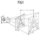
- the projection module 1 shows the perspective view of a projection module 1 to illustrate the principle of image expansion by means of projection technology.
- the projection module 1 consists of a light source 2 with a defined emission characteristic 2 ⁇ for backlighting the information to be displayed.
- the light source 2 consists of an optical fiber bundle 11 with a radiation characteristic 2 ⁇ of approximately 60 °.
- the effective opening angle of a light guide is referred to as the radiation characteristic 2 ⁇ .
- the effective opening angle of a light guide results from the full width at half maximum of the measured angle-dependent radiation distribution at the light guide output if the light guide input is illuminated with a Lambertian lamp.
- the light source 2 shines through a liquid crystal cell 3 which has a peripheral contact edge 12.
- the liquid crystal cell 3 acts as a light valve and contains the information to be displayed.
- the scattering projection surface 4 forms the viewing plane, on which the information in shown on an enlarged scale.
- the projection distance d between the projection surface 4 and the liquid cell 3 depends on the desired magnification factor.
- FIG. 2 the relationships that must be observed in order to obtain a complete picture of the information to be displayed by means of two projection modules 1 are shown on the basis of two adjacent projection modules 1.
- the method uses the magnification effect of a shadow projection in the divergent beam path of a light source.
- the light source 2 used for each individual module 1 must meet this condition, ie, in addition to the outputs of light guides mentioned, halogen spotlights with defined radiation characteristics can also be used.
- the projection surface 4 arranged between the light source 2 and the viewer 15 must be a scattering surface, for example a Be a focusing screen.
- the scatter characteristics can be significantly improved by using thin, white-colored glasses or by foils (opal effect). This effect can also be achieved by combining a diffusing surface with a Fresnel lens.
- an aperture 5 in each case in the plane of the control element, here the liquid crystal cells 3.
- the aperture 5 is formed by the inner slope of the housing 8. Since the required magnification is usually below 10%, there is no need for other optical aids. A slight blurring of the image is irrelevant for viewing from a distance as is usual for large projections.
- Each projection module 1 is supplied with light from a central light source unit 9 via flexible light guides 13, which open into polished end pieces 14 and form the light source 2.
- the light emerges from these end pieces 14 at a defined angle 2 ⁇ and shines through the respective light valves, here liquid crystal cells 3, so that on the projection surface 4, which is arranged at a defined distance d from the light valves, from the partial projections of the image parts 6 for the viewer 15 a homogeneous overall picture 7 is created.
- the individual projection modules 1 are combined in a housing 8.
- the control of the light valves, here the liquid crystal cells 3, takes place via control electronics 10.
Landscapes
- Engineering & Computer Science (AREA)
- Theoretical Computer Science (AREA)
- Physics & Mathematics (AREA)
- General Physics & Mathematics (AREA)
- Business, Economics & Management (AREA)
- Crystallography & Structural Chemistry (AREA)
- Chemical & Material Sciences (AREA)
- Accounting & Taxation (AREA)
- Marketing (AREA)
- Liquid Crystal (AREA)
- Holo Graphy (AREA)
- Projection Apparatus (AREA)
- Transforming Electric Information Into Light Information (AREA)
Abstract
Description
Die Erfindung bezieht sich auf ein Verfahren und eine Anordnung zur optischen Darstellung von Informationen gemäß dem Oberbegriff des Anspruches 1.The invention relates to a method and an arrangement for the optical representation of information according to the preamble of
Die großflächige Darstellung von Informationen erfolgt in bekannter Weise durch die normale Projektion mittels eines Overhead-Projektors. Die Intensität der direkten Beleuchtung muß wegen des erforderlichen Vergrößerungsverhältnisses sehr groß sein. Es entstehen Probleme bei der Langzeitstabilität und der Lebensdauer.The large-scale display of information takes place in a known manner by normal projection using an overhead projector. The intensity of the direct lighting must be very high because of the required magnification ratio. There are problems with long-term stability and durability.
Der Stand der Entwicklung von Flüssigkristall-Anzeigen erlaubt es, großflächige Anzeigepaneele auch durch die matrixförmige Aneinanderreihung von kleinen Flüssigkristall-Anzeigen aufzubauen. In diesem Falle begrenzen die Abstände zwischen den einzelnen Anzeigen die Auflösung des Displays. Die optisch nicht nutzbaren Flächen ergeben sich aus der Breite des Hermetisierungsrahmens der Einzelelemente und der Breite der elektrischen Kontaktierung.The state of development of liquid crystal displays allows It is also possible to build up large-area display panels through the matrix-like arrangement of small liquid crystal displays. In this case, the distances between the individual displays limit the resolution of the display. The optically unusable areas result from the width of the hermetic frame of the individual elements and the width of the electrical contact.
In der gattungsfremden DE 30 40 551 A1 wird vorgeschlagen, durch Hilfsmontagen diese Flächen teilweise zu verkleinern. Dazu werden die Tragplatten der einzelnen Flüssigkristall-Anzeigeeinheiten nur auf den Seiten, an denen sich keine Nachbar-Anzeigeeinheiten anschließen, durch eine Harzdichtung verbunden. Die Anzeigeelektroden benachbarter Anzeigeeinheiten können dicht aneinandergerückt werden.In the non-generic DE 30 40 551 A1 it is proposed to partially reduce these areas by auxiliary assemblies. For this purpose, the support plates of the individual liquid crystal display units are connected by a resin seal only on the sides to which no neighboring display units are connected. The display electrodes of adjacent display units can be moved close together.
In der ebenfalls gattungsfremden DE-40 04 739 A1 wird ein optisches System zur stereoskopischen Darstellung von Informationen mit einem optischen Element mit Linsenfunktion, einer Lichtquelle und mit einem zumindestens teilweise transparenten flächenförmigen Informationsträger beschrieben, bei welchem auf der dem Betrachter gegenüberliegenden Seite des optischen Elementes zwei Lichtquellen angeordnet sind und bei dem sich der Informationsträger im Bereich der Aperturblende des optischen Elementes befindet. Bei diesem System entsteht das Bild im Auge des Betrachters, es wird keine Projektionsfläche zur Abbildung benötigt. Die Vermeidung von optisch nicht nutzbaren Zonen wird nicht angestrebt.DE-40 04 739 A1, also of a non-generic type, describes an optical system for the stereoscopic display of information with an optical element with a lens function, a light source and with an at least partially transparent sheet-like information carrier, in which two are on the side of the optical element opposite the viewer Light sources are arranged and in which the information carrier is located in the area of the aperture diaphragm of the optical element. With this system, the image is created in the eye of the beholder, no projection surface is required for the image. The aim is not to avoid optically usable zones.
Der Erfindung liegt von daher die Aufgabe zugrunde, ein Verfahren und eine Anordnung zur optischen Darstellung von Informationen zu entwickeln, welches kostengünstig ist und das für den Betrachter auch bei der großflächigen Darstellung von Informationen ein helles, kontrastreiches, homogenes Bild gewährleistet.The invention is therefore based on the object of developing a method and an arrangement for the optical display of information which is inexpensive and which also provides the viewer with a bright, high-contrast, homogeneous image when displaying information over a large area guaranteed.
Die Lösung dieser Aufgabe ergibt sich aus den kennzeichnenden Merkmalen der Ansprüche 1 und 3.The solution to this problem results from the characterizing features of
Durch die Ausnutzung des Vergrößerungseffektes einer Schattenprojektion im divergenten Strahlengang einer Lichtquelle wird erreicht, daß die reellen Bildteile, die pro Projektionsmodul auf einer Projektionsfläche entstehen, derart aneinandergefügt werden, daß ein lückenloses Gesamtbild auf der Projektionsfläche entsteht. Der Abstand zwischen einem Lichtventil, beispielsweise einer Flüssigkristallzelle, und der Pojektionsfläche, der Projektionsabstand, wird in Abhängigkeit vom vorhandenen, optisch nicht nutzbaren umlaufenden Rand der Flüssigkristallzelle, vom Öffnungswinkel der Lichtquelle, beispielsweise eines Lichtwellenleiters, und von der gewünschten Vergrößerung so gewählt, daß die um ca. 10% vergrößerten Schattenbilder aus den Flüssigkristallzellen so aneinandergefügt werden, daß die nicht angesteuerten Randflächen der Flüssigkristallzellen ausgeblendet und die angesteuerten Flächen der Flüssigkristallzellen auf der Projektionsfläche lückenlos aneinandergereiht werden. Da die benötigte Vergrößerung in der Regel kleiner als 10% ist, kann auf weitere optische Hilfsmittel verzichtet werden. Eine geringfügige Unschärfe der Abbildung ist für die Betrachtung aus Entfernungen, wie sie für Großprojektionen üblich sind, bedeutungslos. Es wird ein kompaktes und kostengünstiges Projektionssystem für die großflächige Informationsdarstellung auf der Basis von Flüssigkristallzellen erzielt, mit dem auf einer streuenden Projektionsfläche ein homogenes reelles Bild erzeugt werden kann, bei dem die Modulbegrenzungen nicht sichtbar sind.By utilizing the magnification effect of a shadow projection in the divergent beam path of a light source, it is achieved that the real parts of the image that are created for each projection module on a projection surface are joined together in such a way that a complete image is created on the projection surface. The distance between a light valve, for example a liquid crystal cell, and the projection surface, the projection distance, is selected as a function of the existing, optically unusable peripheral edge of the liquid crystal cell, the opening angle of the light source, for example an optical waveguide, and the desired magnification such that the by approx. 10% enlarged shadow images from the liquid crystal cells are joined together in such a way that the uncontrolled peripheral surfaces of the liquid crystal cells are hidden and the controlled surfaces of the liquid crystal cells are strung together without gaps on the projection surface. Since the required magnification is generally less than 10%, there is no need for further optical aids. A slight blurring of the image is irrelevant for viewing from a distance as is usual for large projections. A compact and inexpensive projection system for the large-scale information display based on liquid crystal cells is achieved, with which a homogeneous real image can be generated on a scattering projection surface, in which the module boundaries are not visible.
Weitere vorteilhafte Ausgestaltungen der Erfindung ergeben sich aus den Unteransprüchen.Further advantageous embodiments of the invention result itself from the subclaims.
Die Erfindung ist nachfolgend anhand eines in den Zeichnungen dargestellten Ausführungsbeispieles einer Anordnung zur optischen Darstellung von Informationen näher erläutert. Es zeigen:
- Fig. 1
- die schematische perspektivische Ansicht eines Projektionsmoduls,
- Fig. 2
- die schematische Seitenansicht zweier benachbarter Projektionsmodule und
- Fig. 3
- die schematische Seitenansicht einer Anordnung mit mehreren Projektionsmodulen.
- Fig. 1
- the schematic perspective view of a projection module,
- Fig. 2
- the schematic side view of two adjacent projection modules and
- Fig. 3
- the schematic side view of an arrangement with several projection modules.
Die Fig. 1 zeigt zur Verdeutlichung des Prinzips der Bildaufweitung mittels Projektionstechnik die perspektivische Ansicht eines Projektionsmodules 1. Das Projektionsmodul 1 besteht aus einer Lichtquelle 2 mit definierter Abstrahlcharakteristik 2α zur Hinterleuchtung der darzustellenden Information. Im vorliegenden Beispiel besteht die Lichtquelle 2 aus einem Lichtleiterbündel 11 mit einer Abstrahlcharakteristik 2α von ca. 60°. Als Abstrahlcharakteristik 2α wird der effektive Öffnungswinkel eines Lichtleiters bezeichnet. Der effektive Öffnungswinkel eines Lichtleiters ergibt sich aus der Halbwertsbreite der gemessenen winkelabhängigen Strahlungsverteilung am Lichtleiterausgang, wenn der Lichtleitereingang mit einem Lambert'schen Strahler beleuchtet wird. Die Lichtquelle 2 durchstrahlt eine Flüssigkristallzelle 3, welche einen umlaufenden Kontaktierungsrand 12 aufweist. Die Flüssigkristallzelle 3 wirkt als Lichtventil und enthält die darzustellende Information. Die streuende Projektionsfläche 4 bildet die Betrachtungsebene, auf ihr wird die Information in vergrößertem Maßstab abgebildet. Der Projektionsabstand d zwischen der Projektionsfläche 4 und der Flüssigkeitszelle 3 hängt von dem gewünschten Vergrößerungsfaktor ab.1 shows the perspective view of a
In der Fig. 2 werden anhand von zwei benachbarten Projektionsmodulen 1 die Zusammenhänge aufgezeigt, die beachtet werden müssen, um mittels mehrerer Projektionsmodule 1 ein lückenloses Gesamtbild einer darzustellenen Information zu bekommen. Die Lichtquellen 2 durchstrahlen jeweils mit einem Öffnungswinkel von ca. 60° jeweils eine Flüssigkristallzelle 3, die jeweils eine Höhe H2 aufweisen und welche Teile der darzustellenden Information enthalten. Wenn eine ca. 10%ige Vergrößerung des Bidlteiles 6 auf der Projektionsfläche 4 erzielt werden soll und wenn beide Bildteile 6 jeder Flüssigkristallzelle 3 lückenlos aneinandergefügt sein sollen, dann muß der Abstand d zwischen den Flüssigkristallzellen 3 und der Projektionsfläche 4 mit der jeweiligen Höhe H1 nach folgender Beziehung gewählt werden:
wobei H1 = 1,1 x H2, 2α = 60° gewählt sind. In der Praxis hat sich ein Projektionsabstand d von ca. 5 mm bewährt.In FIG. 2, the relationships that must be observed in order to obtain a complete picture of the information to be displayed by means of two
where H1 = 1.1 x H2, 2α = 60 ° are selected. In practice, a projection distance d of approx. 5 mm has proven itself.
Das Verfahren nutzt den Vergrößerungseffekt einer Schattenprojektion im divergenten Strahlengang einer Lichtquelle aus. Die für jedes Einzelmodul 1 eingesetzte Lichtquelle 2 muß diese Bedingung erfüllen, d.h. es können neben den angeführten Ausgängen von Lichtleitern auch Halogenpunktstrahler mit definierter Abstrahlcharakteristik verwendet werden. Die zwischen der Lichtquelle 2 und dem Betrachter 15 angeordnete Projektionsfläche 4 muß eine streuende Fläche , z.B. eine Mattscheibe sein. Die Streucharakteristik kann durch die Verwendung von dünnen, weiß eingefärbten Gläsern oder durch Folien (Opaleffekt) wesentlich verbessert werden. Man kann diesen Effekt auch durch die Kombination einer Streufläche mit einer Fresnel'schen Stufenlinse erreichen. Um die Strahlengänge benachbarter Module 1 zu entkoppeln ist es günstig, jeweils eine Blende 5 in der Ebene des Ansteuerelementes, hier der Flüssigkristallzellen 3, anzuordnen. In der Fig.3 wird die Blende 5 durch die innere Schräge des Gehäuses 8 gebildet. Da die benötigte Vergrößerung in der Regel unter 10% liegt, kann auf weitere optische Hilfsmittel verzichtet werden. Eine geringfügige Unschärfe der Abbildung ist für die Betrachtung aus Entfernungen, wie sie für Großprojektionen üblich sind, bedeutungslos.The method uses the magnification effect of a shadow projection in the divergent beam path of a light source. The
In der Fig. 3 ist eine Anordnung mit vier Projektionsmodulen 1 dargestellt, wie sie für eine großflächige Darstellung von Informationen benötigt wird. Jedes Projektionsmodul 1 wird aus einer zentralen Lichtquelleneinheit 9 über flexible Lichtleiter 13, welche in polierten Endstücken 14 münden und die Lichtquelle 2 bilden, mit Licht gespeist. Das Licht tritt aus diesen Endstücken 14 in einem definierten Winkel 2α aus und durchstrahlt die jeweiligen Lichtventile, hier Flüssigkristallzellen 3 so, daß auf der Projektionsfläche 4, welche im definierten Abstand d von den Lichtventilen angeordnet ist, aus den Teilprojektionen der Bildteile 6 für den Betrachter 15 ein homogenes Gesamtbild 7 entsteht. Die einzelnen Projektionsmodule 1 sind in einem Gehäuse 8 zusammengefaßt. Die Ansteuerung der Lichtventile, hier der Flüssigkristallzellen 3, erfolgt über eine Steuerelektronik 10.3 shows an arrangement with four
- 11
- ProjektionsmodulProjection module
- 22nd
- LichtquelleLight source
- 33rd
- Lichtventil (Flüssigkristallzelle)Light valve (liquid crystal cell)
- 44th
- ProjektionsflächeProjection surface
- 55
- Blendecover
- 66
- BildteilPart of the picture
- 77
- GesamtbildOverall picture
- 88th
- Gehäusecasing
- 99
- LichtquelleneinheitLight source unit
- 1010th
- SteuerelektronikControl electronics
- 1111
- LichtleiterbündelOptical fiber bundle
- 1212th
- KontaktierungsrandContact edge
- 1313
- LichtleiterLight guide
- 1414
- EndstückTail
- 1515
- BetrachterViewer
- dd
- ProjektionsabstandProjection distance
- 2α2α
- Abstrahlcharakteristik/ÖffnungswinkelBeam pattern / opening angle
- H1H1
- Höhe des vergrößerten BildteilesHeight of the enlarged part of the picture
- H2H2
- Höhe des zu vergrößernden BildteilesHeight of the part of the image to be enlarged
Claims (12)
dadurch gekennzeichnet,
daß von jedem der Projektionsmodule (1) eine Schattenprojektion eines Bildteiles (6) auf der Projektionsfläche (4) erzeugt wird, und daß die Schattenprojektionen der Bildteile (6) auf der Projektionsfläche (4) lückenlos zu einem reelen Gesamtbild (7) aneinander gefügt werden.Method for the optical representation of information with several projection modules on a transparent projection surface in transmitted light projection,
characterized,
that each of the projection modules (1) produces a shadow projection of an image part (6) on the projection surface (4), and that the shadow projections of the image parts (6) on the projection surface (4) are seamlessly joined together to form a real overall image (7) .
Applications Claiming Priority (2)
| Application Number | Priority Date | Filing Date | Title |
|---|---|---|---|
| DE4244448 | 1992-12-23 | ||
| DE4244448A DE4244448C2 (en) | 1992-12-23 | 1992-12-23 | Method and arrangement for the optical representation of information |
Publications (2)
| Publication Number | Publication Date |
|---|---|
| EP0603465A1 true EP0603465A1 (en) | 1994-06-29 |
| EP0603465B1 EP0603465B1 (en) | 1999-04-21 |
Family
ID=6476769
Family Applications (1)
| Application Number | Title | Priority Date | Filing Date |
|---|---|---|---|
| EP93114019A Expired - Lifetime EP0603465B1 (en) | 1992-12-23 | 1993-09-02 | Method and device for optical presentation of information |
Country Status (5)
| Country | Link |
|---|---|
| US (1) | US5664353A (en) |
| EP (1) | EP0603465B1 (en) |
| AT (1) | ATE179272T1 (en) |
| AU (1) | AU671140B2 (en) |
| DE (2) | DE4244448C2 (en) |
Cited By (1)
| Publication number | Priority date | Publication date | Assignee | Title |
|---|---|---|---|---|
| DE19654440A1 (en) * | 1996-12-30 | 1998-07-02 | Mediatec Ges Fuer Multimediale | Device and method for the large-scale display of information by means of liquid crystal displays |
Families Citing this family (8)
| Publication number | Priority date | Publication date | Assignee | Title |
|---|---|---|---|---|
| JPH09159985A (en) * | 1995-12-08 | 1997-06-20 | Mitsubishi Electric Corp | Picture display system |
| JPH10301202A (en) * | 1997-02-28 | 1998-11-13 | R D S Kk | Multiprojection system |
| US6247815B1 (en) * | 1997-06-16 | 2001-06-19 | Metavision Corporation | Work desk with panoramic display |
| US5902030A (en) * | 1998-05-29 | 1999-05-11 | Blanchard; Randall D. | System for displaying images from multiple projectors onto a common screen |
| KR100629757B1 (en) * | 2005-04-19 | 2006-09-29 | 심기섭 | Advertisement apparatus using optic image |
| US7334901B2 (en) * | 2005-04-22 | 2008-02-26 | Ostendo Technologies, Inc. | Low profile, large screen display using a rear projection array system |
| US9902644B2 (en) | 2014-06-19 | 2018-02-27 | Corning Incorporated | Aluminosilicate glasses |
| CN108074509B (en) * | 2018-01-25 | 2020-08-14 | 台州市皓仔邦工业设计有限公司 | Directional rotating polarized light reflection advertisement improvement device and control method thereof |
Citations (5)
| Publication number | Priority date | Publication date | Assignee | Title |
|---|---|---|---|---|
| DE2924101A1 (en) * | 1978-06-29 | 1980-01-10 | Michael Stolov | MULTICOLOR IMAGE PROJECTION SYSTEM |
| FR2607301A1 (en) * | 1986-11-25 | 1988-05-27 | Matra | Modular, liquid crystal display device |
| EP0349404A1 (en) * | 1988-06-28 | 1990-01-03 | France Telecom | Gigantic liquid crystal display |
| JPH0317615A (en) * | 1989-06-14 | 1991-01-25 | Seiko Instr Inc | Overhead projector for ordinary paper |
| JPH0385879A (en) * | 1989-08-29 | 1991-04-11 | Seiko Epson Corp | Projection type display device |
Family Cites Families (15)
| Publication number | Priority date | Publication date | Assignee | Title |
|---|---|---|---|---|
| BE509684A (en) * | ||||
| US1065845A (en) * | 1910-10-24 | 1913-06-24 | Fernand Sauvage | Optical indicating apparatus. |
| US3020798A (en) * | 1957-09-17 | 1962-02-13 | Charles M Chrisman | Projection advertising |
| US3198066A (en) * | 1962-03-01 | 1965-08-03 | Clarence L Mcghee | Outdoor advertising device including projection means |
| US3796484A (en) * | 1971-08-20 | 1974-03-12 | Holograph Corp | Optical communication system providing selective image presentations |
| US4116553A (en) * | 1977-01-21 | 1978-09-26 | Cohen Norman E | Display method and apparatus |
| US4257041A (en) * | 1978-06-19 | 1981-03-17 | Izon Corporation | Electro optical display device |
| IL55032A (en) * | 1978-06-29 | 1984-05-31 | Stolov Michael | Color picture display system including electronically controlled slides |
| JPS5664315A (en) * | 1979-10-29 | 1981-06-01 | Sharp Corp | Production of liquid crystal display panel |
| FR2471012A1 (en) * | 1979-12-07 | 1981-06-12 | Commissariat Energie Atomique | LIGHTING DEVICE FOR LARGE SCREEN |
| DE8124380U1 (en) * | 1981-08-20 | 1983-03-24 | Siemens AG, 1000 Berlin und 8000 München | INTERCHANGEABLE DISPLAY DEVICE, IN PARTICULAR FOR TRAFFIC SIGNAL INDICATORS |
| JPS60203915A (en) * | 1984-03-28 | 1985-10-15 | Matsushita Electric Ind Co Ltd | Large-sized liquid crystal display device |
| US4954935A (en) * | 1989-02-08 | 1990-09-04 | Holophane Company, Inc. | Lighting system for illuminating billboards and the like |
| JP2898673B2 (en) * | 1989-05-10 | 1999-06-02 | 株式会社日立製作所 | Multi-screen projector and projector device |
| DE4004739A1 (en) * | 1990-02-15 | 1991-08-22 | Holtronic Gmbh | Optical system for stereoscopic information display - uses left and right hand light sources activated in alternation for illuminating display |
-
1992
- 1992-12-23 DE DE4244448A patent/DE4244448C2/en not_active Expired - Fee Related
-
1993
- 1993-09-02 DE DE59309529T patent/DE59309529D1/en not_active Expired - Fee Related
- 1993-09-02 AT AT93114019T patent/ATE179272T1/en not_active IP Right Cessation
- 1993-09-02 EP EP93114019A patent/EP0603465B1/en not_active Expired - Lifetime
- 1993-09-10 AU AU46246/93A patent/AU671140B2/en not_active Ceased
- 1993-11-17 US US08/153,631 patent/US5664353A/en not_active Expired - Fee Related
Patent Citations (5)
| Publication number | Priority date | Publication date | Assignee | Title |
|---|---|---|---|---|
| DE2924101A1 (en) * | 1978-06-29 | 1980-01-10 | Michael Stolov | MULTICOLOR IMAGE PROJECTION SYSTEM |
| FR2607301A1 (en) * | 1986-11-25 | 1988-05-27 | Matra | Modular, liquid crystal display device |
| EP0349404A1 (en) * | 1988-06-28 | 1990-01-03 | France Telecom | Gigantic liquid crystal display |
| JPH0317615A (en) * | 1989-06-14 | 1991-01-25 | Seiko Instr Inc | Overhead projector for ordinary paper |
| JPH0385879A (en) * | 1989-08-29 | 1991-04-11 | Seiko Epson Corp | Projection type display device |
Non-Patent Citations (2)
| Title |
|---|
| PATENT ABSTRACTS OF JAPAN vol. 15, no. 140 (P - 1188) 9 April 1991 (1991-04-09) * |
| PATENT ABSTRACTS OF JAPAN vol. 15, no. 261 (E - 1085) 3 July 1991 (1991-07-03) * |
Cited By (1)
| Publication number | Priority date | Publication date | Assignee | Title |
|---|---|---|---|---|
| DE19654440A1 (en) * | 1996-12-30 | 1998-07-02 | Mediatec Ges Fuer Multimediale | Device and method for the large-scale display of information by means of liquid crystal displays |
Also Published As
| Publication number | Publication date |
|---|---|
| DE59309529D1 (en) | 1999-05-27 |
| ATE179272T1 (en) | 1999-05-15 |
| DE4244448A1 (en) | 1994-07-07 |
| AU671140B2 (en) | 1996-08-15 |
| AU4624693A (en) | 1994-07-07 |
| US5664353A (en) | 1997-09-09 |
| DE4244448C2 (en) | 1995-04-13 |
| EP0603465B1 (en) | 1999-04-21 |
Similar Documents
| Publication | Publication Date | Title |
|---|---|---|
| DE69906512T2 (en) | PROJECTION DISPLAY DEVICE | |
| DE69724411T3 (en) | LIGHTING DEVICE AND DISPLAY WHICH IT USES | |
| JP2815910B2 (en) | Projection image display device | |
| DE112017000008B4 (en) | STEREOSCOPIC DISPLAY DEVICE | |
| DE102006055327B4 (en) | A light guide, parallax barrier, and three-dimensional image display device, and image forming method using the same | |
| EP1695562A1 (en) | Multi-user autostereoscopic display with position tracking | |
| DE112018002005T5 (en) | Image display device | |
| EP0309528A1 (en) | Stereoscopic display system. | |
| WO2009156130A1 (en) | Projection system | |
| EP1018101B1 (en) | Flat display screen | |
| DE4244448C2 (en) | Method and arrangement for the optical representation of information | |
| DE112017001785T5 (en) | Head-up display | |
| DE112019002950T5 (en) | Display device and head-up display device | |
| DE102018200873A1 (en) | Autostereoscopic field of view display device for a vehicle, vehicle with an autostereoscopic field of view display device and method for generating an autostereoscopic image | |
| EP0010796B1 (en) | Display device consisting of an electrooptical liquid cell | |
| DE69929622T2 (en) | PROJECTION SYSTEM | |
| DE10157605C1 (en) | Image-projection arrangement, e.g. for vehicle display, incorporates combiner, reflux surface mirrors, concave mirrors, display and screen | |
| DE112020005892T5 (en) | ELECTRONIC DEVICE | |
| DE19809506A1 (en) | Real image viewfinder for photographic or video camera | |
| WO1997044696A1 (en) | Head-mounted display | |
| AT390851B (en) | DEVICE FOR THE PRESENTATION OF INFORMATION, DISPLAYS, NOTES ETC. | |
| DE112020004339T5 (en) | LIGHT SOURCE DEVICE AND INFORMATION DISPLAY SYSTEM USING THE SAME | |
| DE19907345B4 (en) | Device for displaying an image that can be represented as a raster of pixels on a screen | |
| DE2809067C2 (en) | ||
| CH696216A5 (en) | Line illumination. |
Legal Events
| Date | Code | Title | Description |
|---|---|---|---|
| PUAI | Public reference made under article 153(3) epc to a published international application that has entered the european phase |
Free format text: ORIGINAL CODE: 0009012 |
|
| AK | Designated contracting states |
Kind code of ref document: A1 Designated state(s): AT BE CH DE DK ES FR GB GR IE IT LI LU MC NL PT SE |
|
| 17P | Request for examination filed |
Effective date: 19940725 |
|
| 17Q | First examination report despatched |
Effective date: 19950831 |
|
| RAP1 | Party data changed (applicant data changed or rights of an application transferred) |
Owner name: MAN SYSTEMELEKTRONIK GMBH |
|
| GRAG | Despatch of communication of intention to grant |
Free format text: ORIGINAL CODE: EPIDOS AGRA |
|
| GRAG | Despatch of communication of intention to grant |
Free format text: ORIGINAL CODE: EPIDOS AGRA |
|
| GRAH | Despatch of communication of intention to grant a patent |
Free format text: ORIGINAL CODE: EPIDOS IGRA |
|
| GRAH | Despatch of communication of intention to grant a patent |
Free format text: ORIGINAL CODE: EPIDOS IGRA |
|
| GRAH | Despatch of communication of intention to grant a patent |
Free format text: ORIGINAL CODE: EPIDOS IGRA |
|
| GRAH | Despatch of communication of intention to grant a patent |
Free format text: ORIGINAL CODE: EPIDOS IGRA |
|
| GRAA | (expected) grant |
Free format text: ORIGINAL CODE: 0009210 |
|
| AK | Designated contracting states |
Kind code of ref document: B1 Designated state(s): AT BE CH DE DK ES FR GB GR IE IT LI LU MC NL PT SE |
|
| PG25 | Lapsed in a contracting state [announced via postgrant information from national office to epo] |
Ref country code: SE Free format text: THE PATENT HAS BEEN ANNULLED BY A DECISION OF A NATIONAL AUTHORITY Effective date: 19990421 Ref country code: IT Free format text: LAPSE BECAUSE OF FAILURE TO SUBMIT A TRANSLATION OF THE DESCRIPTION OR TO PAY THE FEE WITHIN THE PRE;WARNING: LAPSES OF ITALIAN PATENTS WITH EFFECTIVE DATE BEFORE 2007 MAY HAVE OCCURRED AT ANY TIME BEFORE 2007. THE CORRECT EFFECTIVE DATE MAY BE DIFFERENT FROM THE ONE RECORDED.SCRIBED TIME-LIMIT Effective date: 19990421 Ref country code: GR Free format text: LAPSE BECAUSE OF NON-PAYMENT OF DUE FEES Effective date: 19990421 Ref country code: ES Free format text: THE PATENT HAS BEEN ANNULLED BY A DECISION OF A NATIONAL AUTHORITY Effective date: 19990421 |
|
| REF | Corresponds to: |
Ref document number: 179272 Country of ref document: AT Date of ref document: 19990515 Kind code of ref document: T |
|
| REG | Reference to a national code |
Ref country code: CH Ref legal event code: NV Representative=s name: MICHELI & CIE INGENIEURS-CONSEILS Ref country code: CH Ref legal event code: EP |
|
| REG | Reference to a national code |
Ref country code: IE Ref legal event code: FG4D Free format text: GERMAN |
|
| REF | Corresponds to: |
Ref document number: 59309529 Country of ref document: DE Date of ref document: 19990527 |
|
| GBT | Gb: translation of ep patent filed (gb section 77(6)(a)/1977) |
Effective date: 19990629 |
|
| PG25 | Lapsed in a contracting state [announced via postgrant information from national office to epo] |
Ref country code: PT Free format text: LAPSE BECAUSE OF FAILURE TO SUBMIT A TRANSLATION OF THE DESCRIPTION OR TO PAY THE FEE WITHIN THE PRESCRIBED TIME-LIMIT Effective date: 19990721 Ref country code: DK Free format text: LAPSE BECAUSE OF FAILURE TO SUBMIT A TRANSLATION OF THE DESCRIPTION OR TO PAY THE FEE WITHIN THE PRESCRIBED TIME-LIMIT Effective date: 19990721 |
|
| ET | Fr: translation filed | ||
| REG | Reference to a national code |
Ref country code: CH Ref legal event code: PUE Owner name: MAN SYSTEMELEKTRONIK GMBH TRANSFER- VOSSLOH MAN SY Ref country code: CH Ref legal event code: NV Representative=s name: TROESCH SCHEIDEGGER WERNER AG |
|
| RAP2 | Party data changed (patent owner data changed or rights of a patent transferred) |
Owner name: VOSSLOH MAN SYSTEMELEKTRONIK GMBH |
|
| PG25 | Lapsed in a contracting state [announced via postgrant information from national office to epo] |
Ref country code: LU Free format text: LAPSE BECAUSE OF NON-PAYMENT OF DUE FEES Effective date: 19990902 |
|
| REG | Reference to a national code |
Ref country code: FR Ref legal event code: TP |
|
| PG25 | Lapsed in a contracting state [announced via postgrant information from national office to epo] |
Ref country code: BE Free format text: LAPSE BECAUSE OF NON-PAYMENT OF DUE FEES Effective date: 19990930 |
|
| PG25 | Lapsed in a contracting state [announced via postgrant information from national office to epo] |
Ref country code: IE Free format text: LAPSE BECAUSE OF NON-PAYMENT OF DUE FEES Effective date: 19991206 |
|
| REG | Reference to a national code |
Ref country code: IE Ref legal event code: FD4D |
|
| PLBE | No opposition filed within time limit |
Free format text: ORIGINAL CODE: 0009261 |
|
| STAA | Information on the status of an ep patent application or granted ep patent |
Free format text: STATUS: NO OPPOSITION FILED WITHIN TIME LIMIT |
|
| BERE | Be: lapsed |
Owner name: MAN SYSTEMELEKTRONIK G.M.B.H. Effective date: 19990930 |
|
| PG25 | Lapsed in a contracting state [announced via postgrant information from national office to epo] |
Ref country code: MC Free format text: LAPSE BECAUSE OF NON-PAYMENT OF DUE FEES Effective date: 20000331 |
|
| 26N | No opposition filed | ||
| REG | Reference to a national code |
Ref country code: CH Ref legal event code: PFA Free format text: VOSSLOH MAN SYSTEMELEKTRONIK GMBH TRANSFER- VOSSLOH SYSTEMELEKTRONIK GMBH |
|
| NLT1 | Nl: modifications of names registered in virtue of documents presented to the patent office pursuant to art. 16 a, paragraph 1 |
Owner name: VOSSLOH SYSTEMELEKTRONIK GMBH |
|
| REG | Reference to a national code |
Ref country code: FR Ref legal event code: CD |
|
| REG | Reference to a national code |
Ref country code: GB Ref legal event code: IF02 |
|
| PGFP | Annual fee paid to national office [announced via postgrant information from national office to epo] |
Ref country code: CH Payment date: 20080923 Year of fee payment: 16 |
|
| PGFP | Annual fee paid to national office [announced via postgrant information from national office to epo] |
Ref country code: NL Payment date: 20080922 Year of fee payment: 16 Ref country code: FR Payment date: 20080917 Year of fee payment: 16 Ref country code: AT Payment date: 20080919 Year of fee payment: 16 |
|
| PGFP | Annual fee paid to national office [announced via postgrant information from national office to epo] |
Ref country code: GB Payment date: 20080922 Year of fee payment: 16 |
|
| PGFP | Annual fee paid to national office [announced via postgrant information from national office to epo] |
Ref country code: DE Payment date: 20080826 Year of fee payment: 16 |
|
| REG | Reference to a national code |
Ref country code: NL Ref legal event code: V1 Effective date: 20100401 |
|
| REG | Reference to a national code |
Ref country code: CH Ref legal event code: PL |
|
| GBPC | Gb: european patent ceased through non-payment of renewal fee |
Effective date: 20090902 |
|
| REG | Reference to a national code |
Ref country code: FR Ref legal event code: ST Effective date: 20100531 |
|
| PG25 | Lapsed in a contracting state [announced via postgrant information from national office to epo] |
Ref country code: AT Free format text: LAPSE BECAUSE OF NON-PAYMENT OF DUE FEES Effective date: 20090902 |
|
| PG25 | Lapsed in a contracting state [announced via postgrant information from national office to epo] |
Ref country code: NL Free format text: LAPSE BECAUSE OF NON-PAYMENT OF DUE FEES Effective date: 20100401 Ref country code: FR Free format text: LAPSE BECAUSE OF NON-PAYMENT OF DUE FEES Effective date: 20090930 Ref country code: DE Free format text: LAPSE BECAUSE OF NON-PAYMENT OF DUE FEES Effective date: 20100401 |
|
| PG25 | Lapsed in a contracting state [announced via postgrant information from national office to epo] |
Ref country code: LI Free format text: LAPSE BECAUSE OF NON-PAYMENT OF DUE FEES Effective date: 20090930 Ref country code: CH Free format text: LAPSE BECAUSE OF NON-PAYMENT OF DUE FEES Effective date: 20090930 |
|
| PG25 | Lapsed in a contracting state [announced via postgrant information from national office to epo] |
Ref country code: GB Free format text: LAPSE BECAUSE OF NON-PAYMENT OF DUE FEES Effective date: 20090902 |