EP0603038B1 - Eddy current slow-down assembly - Google Patents
Eddy current slow-down assembly Download PDFInfo
- Publication number
- EP0603038B1 EP0603038B1 EP93402987A EP93402987A EP0603038B1 EP 0603038 B1 EP0603038 B1 EP 0603038B1 EP 93402987 A EP93402987 A EP 93402987A EP 93402987 A EP93402987 A EP 93402987A EP 0603038 B1 EP0603038 B1 EP 0603038B1
- Authority
- EP
- European Patent Office
- Prior art keywords
- temperature
- armature
- instant
- stator
- succession
- Prior art date
- Legal status (The legal status is an assumption and is not a legal conclusion. Google has not performed a legal analysis and makes no representation as to the accuracy of the status listed.)
- Expired - Lifetime
Links
Images
Classifications
-
- B—PERFORMING OPERATIONS; TRANSPORTING
- B60—VEHICLES IN GENERAL
- B60L—PROPULSION OF ELECTRICALLY-PROPELLED VEHICLES; SUPPLYING ELECTRIC POWER FOR AUXILIARY EQUIPMENT OF ELECTRICALLY-PROPELLED VEHICLES; ELECTRODYNAMIC BRAKE SYSTEMS FOR VEHICLES IN GENERAL; MAGNETIC SUSPENSION OR LEVITATION FOR VEHICLES; MONITORING OPERATING VARIABLES OF ELECTRICALLY-PROPELLED VEHICLES; ELECTRIC SAFETY DEVICES FOR ELECTRICALLY-PROPELLED VEHICLES
- B60L7/00—Electrodynamic brake systems for vehicles in general
- B60L7/28—Eddy-current braking
-
- H—ELECTRICITY
- H02—GENERATION; CONVERSION OR DISTRIBUTION OF ELECTRIC POWER
- H02P—CONTROL OR REGULATION OF ELECTRIC MOTORS, ELECTRIC GENERATORS OR DYNAMO-ELECTRIC CONVERTERS; CONTROLLING TRANSFORMERS, REACTORS OR CHOKE COILS
- H02P21/00—Arrangements or methods for the control of electric machines by vector control, e.g. by control of field orientation
-
- B—PERFORMING OPERATIONS; TRANSPORTING
- B60—VEHICLES IN GENERAL
- B60L—PROPULSION OF ELECTRICALLY-PROPELLED VEHICLES; SUPPLYING ELECTRIC POWER FOR AUXILIARY EQUIPMENT OF ELECTRICALLY-PROPELLED VEHICLES; ELECTRODYNAMIC BRAKE SYSTEMS FOR VEHICLES IN GENERAL; MAGNETIC SUSPENSION OR LEVITATION FOR VEHICLES; MONITORING OPERATING VARIABLES OF ELECTRICALLY-PROPELLED VEHICLES; ELECTRIC SAFETY DEVICES FOR ELECTRICALLY-PROPELLED VEHICLES
- B60L2260/00—Operating Modes
- B60L2260/40—Control modes
- B60L2260/50—Control modes by future state prediction
- B60L2260/56—Temperature prediction, e.g. for pre-cooling
Definitions
- the present invention relates to eddy current deceleration equipment for a vehicle.
- Equipment of this type usually comprises a part fixed to the chassis of the vehicle (stator) comprising inductor windings, and a mobile part (rotor) comprising an armature, linked to a rotary element of the vehicle, generally to its drive shaft.
- inductive winding or simply “winding”, is meant here both an inductive winding proper as well as a group of such windings connected together once and for all in series and / or in parallel. Each winding thus defined produces a magnetic field when powered from the vehicle battery.
- the armature is a body of ferromagnetic material which, when it passes in front of the excited windings, is the seat of induced vortex currents, called eddy currents. Due to the resistivity of the armature, these eddy currents cause a dissipation of energy from which results the slowing down of the rotor and the vehicle. The energy is dissipated in the form of heat, and the rotor is usually given a fin configuration capable of dissipating this heat.
- the driver of the vehicle can actuate a control lever with several positions to obtain a deceleration of the vehicle with a variable torque according to the selected position.
- This variability is obtained by a set of relays which each control the excitation of a winding, the number of closed relays depending on the position of the lever.
- thermosensitive contact housed in a polar expansion of a face of the stator adjacent to the rotor. This contact is sensitive to the heat radiation given off by the armature, and is thus able to provide the desired temperature indication.
- This type of temperature sensor is also provided by certain manufacturers who manufacture rotors with parts which do not withstand strong temperature increases. This is the case, for example, with armature steel rotors and aluminum support, aluminum does not withstand temperatures above 300 ° C.
- the object of the present invention is to provide a simple and economical solution to the above problems.
- the invention thus proposes an eddy current deceleration equipment for a vehicle, comprising a stator comprising inductor windings, a rotor suitable for mounting on a vehicle transmission shaft and comprising an armature opposite the stator, a manual control member.
- control means for establishing a supply setpoint as a function in particular of the position of the manual control member, and excitation means for selectively exciting the inductor windings from an electrical source of the vehicle in response to the supply setpoint
- temperature control means being provided to provide an indication relating to the temperature of the armature, this indication being taken into account by the control means for establishing the supply setpoint
- control means comprise, as temperature control means, a process ur adapted to evaluate in real time the temperature of the armature at successive instants, the temperature of the armature at each instant of the succession being evaluated by the processor according to several calculation variables including the temperature of the armature evaluated at the previous instant of the succession, the speed of rotation of the rotor and the supply setpoint.
- the Applicant has found that, surprisingly, a limited number of calculation variables made it possible to account for the temperature of the armature sufficiently precisely in the context of the intended use of this temperature indication.
- the temperature variation of the armature mainly depends (a) on the supply setpoint, which governs the magnetic field generated by the stator, (b) on the speed of rotation of the rotor, which influences the intensity of the induced currents and the ventilation produced by the movement of the rotor, and (c) the temperature level of the armature on which its resistivity and magnetic permeability depend.
- the calculation parameters also include the temperature of the stator.
- This variable also influences the temperature of the armature by the effect of heat transfers, and especially by its effect on the resistivity of the wire of the windings on which the current in each excited winding and the magnetic field generated depend. Its consideration by the processor therefore allows a more precise evaluation of the temperature of the armature.
- control means are arranged to modify the supply setpoint when the temperature evaluated by the processor exceeds a predetermined threshold, so that the excitation means then connect to the electrical source a number of inductor windings lower than the corresponding number to the position of the manual control member.
- the threshold can be selected during programming of the processor according to the particular configuration of the retarder.
- the information provided by the processor represents a temperature value, and not only the crossing of a predetermined threshold.
- This information is therefore of a richer nature than that provided by the sensors fitted to known retarders, and it is thus possible to envisage making an optimized control of the supply setpoint as a function of the temperature of the armature.
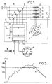
- eddy current deceleration equipment conventionally comprises a stator 1 and a rotor 2.
- the stator 1 is fixed to the chassis of the vehicle and comprises inductor windings 3, which are four in number in the example shown.
- the windings 3 are for example each constituted by a pair of coils, the eight coils being arranged around the transmission shaft (not shown) coming out of the vehicle gearbox, and with their axes parallel to this shaft.
- the rotor 2 is a cast steel part comprising a central bore 4 intended for integral mounting on the drive shaft.
- the rotor 2 comprises one or more discs perpendicular to the transmission shaft which constitute the armature 6 of the rotor.
- each disc Conventionly has a fin structure 7 providing ventilation when the drive shaft rotates.
- the armature 6 When the equipment is assembled on the vehicle, the armature 6 is located opposite the windings 3 of the stator 1.
- the rotor 2 has a disc on each side of the stator, so that each disc-armature 6 scrolls past a ring of magnetic poles of alternating polarities, step by step, created by the windings 3.
- the rotation of the drive shaft generates eddy currents in the armature 6 when at least one of the windings is electrically powered from vehicle battery 8. This results in an increasing deceleration torque with the number of excited windings, and an overheating of the armature which partially compensates for the ventilation by the fins 7.
- the equipment comprises excitation means 9 for selectively supplying the windings 3 from the battery 8, which typically has a nominal voltage of 24 Volts.
- excitation means 9 are constituted by four relays 11 each mounted between the positive terminal of the battery and one end of a respective winding 3, the other end of said winding being connected to the negative terminal of the battery 8.
- the four relays 11 are independently controlled by four signals from the control means 12.
- the control means 12 can also receive other signals and perform other functions not explained here because they are not directly concerned with the invention.
- the input interface 16 formats the aforementioned signals and transmits the corresponding values to the processor 13.
- the latter is programmed to establish a supply setpoint C on the basis of the values P, V, Ts received from the interface 16.
- the processor 13 delivers, via the output interface 17, the four signals which control the opening or closing of each of the relays 11.
- the setpoint C takes one of the five values: 0, 1, 2, 3 or 4, and gives rise to the closing of a corresponding number of relays 11, that is to say to the excitation of a corresponding number of inductor windings 3.
- V / 3000 and a, b1, b2, c1, c2, d1, d2, e1, e2, f2 and kp0 are constant coefficients to be determined for each model, the speed V being expressed in revolutions per minute, the time interval ⁇ t in seconds and temperatures Tr n , Tr n-1 and Ts in degrees Celsius.
- tests can be carried out on a prototype of the retarder.
- a large number of situations characterized by the values of the test variables considered are reproduced on the test bench, and the variations in temperature of the armature during the time interval ⁇ t are measured.
- Each measurement provides a value of the function linking Tr n to the variables Tr n-1 , V, C and Ts.
- the set of coefficients and the data useful for the evaluation according to formula (1) are stored in the memory 14 of the control means 12 of each of the retarders of the model tested.
- the temperature of the armature can thus be evaluated in real time by the processor 13, without it being essential to use a special sensor and to undergo the drawbacks which relate to it.
- thermometer To initialize the algorithm represented by formula (1) before the implementation of the deceleration equipment, one can for example give the temperature of the armature Tr o at the initial time the value Ts of the temperature of the stator, or an ambient temperature value provided by a thermometer.
- the evaluated temperature Tr n is used to establish the control setpoint C during the time interval ⁇ t following the evaluation.
- the processor 13 compares the evaluated temperature Tr n to a predetermined threshold Tmax whose value, chosen as a function of the retarder model, is stored in memory 14.
- Tr n remains below the threshold Tmax, the setpoint C conforms at the position P of the control handle 18, the driver of the vehicle then actuating the handle 18 to directly select the number of excited windings and thus obtain a proportional deceleration torque.
- Tr n exceeds the threshold Tmax, the processor 13 imposes a supply instruction C less than the number corresponding to the position of the lever 18.
- Curve A indicates the evolution of the temperature of the armature Tr in the case where the vehicle is going downhill and where the driver uses different positions of the joystick 18.
- the temperature Tr practically does not exceed the threshold Tmax (approximately 630 ° C in the example shown) because as soon as this occurs, the supply setpoint is reduced.
- the dashed curve B indicates what would be the evolution of Tr under the same conditions if the temperature indication were not taken into account: the threshold Tmax would be greatly exceeded and we would certainly obtain additional torque, but at the price of '' much higher electricity consumption.
- the invention makes it possible to keep a lower temperature (curve A below curve B) so that if a new need for deceleration is encountered before the armature has cooled to room temperature , the immediately available torque is greater than it would be without taking the temperature into account.
- the resistance varies significantly depending on the temperature and can be used to measure it.
Landscapes
- Engineering & Computer Science (AREA)
- Power Engineering (AREA)
- Transportation (AREA)
- Mechanical Engineering (AREA)
- Electric Propulsion And Braking For Vehicles (AREA)
- Discharge Heating (AREA)
- Control Of Ac Motors In General (AREA)
- Emergency Protection Circuit Devices (AREA)
- Magnetic Resonance Imaging Apparatus (AREA)
- Control Of Electric Motors In General (AREA)
- Braking Arrangements (AREA)
- Centrifugal Separators (AREA)
- Dynamo-Electric Clutches, Dynamo-Electric Brakes (AREA)
- Braking Systems And Boosters (AREA)
- Control Of Motors That Do Not Use Commutators (AREA)
Abstract
Description
La présente invention concerne un équipement de ralentissement à courants de Foucault pour véhicule.The present invention relates to eddy current deceleration equipment for a vehicle.
Les équipements de ce type comprennent habituellement une partie fixée au châssis du véhicule (stator) comportant des enroulements inducteurs, et une partie mobile (rotor) comportant un induit, liée à un élément rotatif du véhicule, généralement à son arbre de transmission.Equipment of this type usually comprises a part fixed to the chassis of the vehicle (stator) comprising inductor windings, and a mobile part (rotor) comprising an armature, linked to a rotary element of the vehicle, generally to its drive shaft.
Par "enroulement inducteur", ou simplement "enroulement", on entend ici aussi bien un enroulement inducteur proprement dit qu'un groupe de tels enroulements connectés entre eux une fois pour toutes en série et/ou en parallèle. Chaque enroulement ainsi défini produit un champ magnétique lorsqu'il est alimenté depuis la batterie du véhicule.By “inductive winding”, or simply “winding”, is meant here both an inductive winding proper as well as a group of such windings connected together once and for all in series and / or in parallel. Each winding thus defined produces a magnetic field when powered from the vehicle battery.
L'induit est un corps en matériau ferromagnétique qui, lorsqu'il défile devant les enroulements excités, est le siège de courants tourbillonnaires induits, dits courants de Foucault. Du fait de la résistivité de l'induit, ces courants de Foucault provoquent une dissipation d'énergie d'où résulte le ralentissement du rotor et du véhicule. L'énergie est dissipée sous forme de chaleur, et on donne habituellement au rotor une configuration à ailettes propre à évacuer cette chaleur.The armature is a body of ferromagnetic material which, when it passes in front of the excited windings, is the seat of induced vortex currents, called eddy currents. Due to the resistivity of the armature, these eddy currents cause a dissipation of energy from which results the slowing down of the rotor and the vehicle. The energy is dissipated in the form of heat, and the rotor is usually given a fin configuration capable of dissipating this heat.
Le conducteur du véhicule peut actionner une manette de commande à plusieurs positions pour obtenir un ralentissement du véhicule avec un couple variable selon la position sélectionnée. Cette variabilité est obtenue par un ensemble de relais qui commandent chacun l'excitation d'un enroulement, le nombre de relais fermés dépendant de la position de la manette. Dans une réalisation typique, il y a quatre enroulements inducteurs et cinq positions de manette correspondant respectivement à la fermeture de 0, 1, 2, 3 et 4 relais, et à des couples de ralentissement proportionnels.The driver of the vehicle can actuate a control lever with several positions to obtain a deceleration of the vehicle with a variable torque according to the selected position. This variability is obtained by a set of relays which each control the excitation of a winding, the number of closed relays depending on the position of the lever. In a typical embodiment, there are four inductor windings and five lever positions corresponding respectively to the closing of 0, 1, 2, 3 and 4 relays, and to proportional deceleration torques.
Pour une position donnée, on sait que le couple de ralentissement tend à diminuer lorsque la température de l'induit augmente, à cause des variations de la résistivité et de la perméabilité magnétique de l'induit. Au-delà d'un certain seuil de température, il est judicieux de limiter l'excitation des enroulements pour éviter la perte de couple disponible qui résulterait d'un échauffement excessif. Cette limitation permet en outre une meilleure gestion des ressources en énergie électrique du véhicule.For a given position, we know that the couple of slowing tends to decrease as the temperature of the armature increases, due to variations in the resistivity and magnetic permeability of the armature. Beyond a certain temperature threshold, it is wise to limit the excitation of the windings to avoid the loss of available torque which would result from excessive heating. This limitation also allows better management of the electrical energy resources of the vehicle.
Dans sa précédente demande FR-A-2505577, la demanderesse a décrit une façon d'assurer une telle limitation d'excitation. Le franchissement du seuil de température est détecté au moyen d'un contact thermosensible logé dans un épanouissement polaire d'une face du stator adjacente au rotor. Ce contact est sensible au rayonnement calorifique dégagé par l'induit, et est ainsi apte à fournir l'indication de température désirée.In its previous application FR-A-2505577, the applicant described a way of ensuring such an excitation limitation. The crossing of the temperature threshold is detected by means of a thermosensitive contact housed in a polar expansion of a face of the stator adjacent to the rotor. This contact is sensitive to the heat radiation given off by the armature, and is thus able to provide the desired temperature indication.
Ce type de capteur de température est également prévu par certains constructeurs qui fabriquent des rotors avec des parties qui ne résistent pas aux fortes augmentations de température. C'est le cas par exemple des rotors à induit en acier et support en aluminium, l'aluminium ne résistant pas aux températures supérieures à 300°C.This type of temperature sensor is also provided by certain manufacturers who manufacture rotors with parts which do not withstand strong temperature increases. This is the case, for example, with armature steel rotors and aluminum support, aluminum does not withstand temperatures above 300 ° C.
Le rotor étant mobile, le capteur ne peut pas être en contact thermique direct avec l'induit, sauf à utiliser un montage excessivement compliqué. Le capteur doit donc être monté sur le stator pour recevoir le rayonnement dégagé par l'induit, ce qui pose trois problèmes principaux non résolus jusqu'à présent :
- l'encrassement aléatoire du capteur perturbe la mesure en gênant la réception du rayonnement ;
- il est difficile de rendre le capteur peu dépendant de la température du stator sur lequel il est monté ; et
- il est difficile de réaliser un capteur peu sensible à la chaleur transmise du rotor par circulation de l'air ; or cette circulation n'est pas totalement maîtrisée, notamment à cause des courants d'airs provoqués par les ailettes rotoriques.
- the random fouling of the sensor disturbs the measurement by hampering the reception of the radiation;
- it is difficult to make the sensor little dependent on the temperature of the stator on which it is mounted; and
- it is difficult to produce a sensor that is not very sensitive to the heat transmitted from the rotor by the circulation of air; however this circulation is not completely controlled, in particular because of the air currents caused by the rotor fins.
En outre, le montage du capteur peut être délicat pour certains modèles de ralentisseur.In addition, mounting the sensor can be tricky for some retarder models.
Le but de la présente invention est d'apporter une solution simple et économique aux problèmes ci-dessus.The object of the present invention is to provide a simple and economical solution to the above problems.
L'invention propose ainsi un équipement de ralentissement à courants de Foucault pour véhicule, comprenant un stator comportant des enroulements inducteurs, un rotor adapté au montage sur un arbre de transmission du véhicule et comportant un induit en regard du stator, un organe de commande manuelle à plusieurs positions, des moyens de commande pour établir une consigne d'alimentation en fonction notamment de la position de l'organe de commande manuelle, et des moyens d'excitation pour exciter sélectivement les enroulements inducteurs depuis une source électrique du véhicule en réponse à la consigne d'alimentation, des moyens de contrôle de température étant prévus pour fournir une indication relative à la température de l'induit, cette indication étant prise en compte par les moyens de commande pour l'établissement de la consigne d'alimentation, caractérisé en ce que les moyens de commande comprennent, au titre des moyens de contrôle de température, un processeur adapté pour évaluer en temps réel la température de l'induit à des instants successifs, la température de l'induit à chaque instant de la succession étant évaluée par le processeur en fonction de plusieurs variables de calcul comprenant la température de l'induit évaluée à l'instant précédent de la succession, la vitesse de rotation du rotor et la consigne d'alimentation.The invention thus proposes an eddy current deceleration equipment for a vehicle, comprising a stator comprising inductor windings, a rotor suitable for mounting on a vehicle transmission shaft and comprising an armature opposite the stator, a manual control member. at several positions, control means for establishing a supply setpoint as a function in particular of the position of the manual control member, and excitation means for selectively exciting the inductor windings from an electrical source of the vehicle in response to the supply setpoint, temperature control means being provided to provide an indication relating to the temperature of the armature, this indication being taken into account by the control means for establishing the supply setpoint, characterized in that the control means comprise, as temperature control means, a process ur adapted to evaluate in real time the temperature of the armature at successive instants, the temperature of the armature at each instant of the succession being evaluated by the processor according to several calculation variables including the temperature of the armature evaluated at the previous instant of the succession, the speed of rotation of the rotor and the supply setpoint.
La demanderesse a constaté que, de façon surprenante, un nombre limité de variables de calcul permettait de rendre compte de la température de l'induit de façon suffisamment précise dans le cadre de l'utilisation envisagée de cette indication de température. Entre deux instants d'évaluation successifs, la variation de température de l'induit dépend principalement (a) de la consigne d'alimentation, qui gouverne le champ magnétique généré par le stator, (b) de la vitesse de rotation du rotor, qui influence l'intensité des courants induits et la ventilation produite par le mouvement du rotor, et (c) du niveau de température de l'induit dont dépendent sa résistivité et sa perméabilité magnétique.The Applicant has found that, surprisingly, a limited number of calculation variables made it possible to account for the temperature of the armature sufficiently precisely in the context of the intended use of this temperature indication. Between two successive evaluation moments, the temperature variation of the armature mainly depends (a) on the supply setpoint, which governs the magnetic field generated by the stator, (b) on the speed of rotation of the rotor, which influences the intensity of the induced currents and the ventilation produced by the movement of the rotor, and (c) the temperature level of the armature on which its resistivity and magnetic permeability depend.
Dans une version préférée de l'invention, les paramètres de calcul comprennent en outre la température du stator. Cette variable influence également la température de l'induit par l'effet des transferts de chaleur, et surtout par son effet sur la résistivité du fil des enroulements dont dépendent le courant dans chaque enroulement excité et le champ magnétique généré. Sa prise en considération par le processeur permet donc une évaluation plus précise de la température de l'induit.In a preferred version of the invention, the calculation parameters also include the temperature of the stator. This variable also influences the temperature of the armature by the effect of heat transfers, and especially by its effect on the resistivity of the wire of the windings on which the current in each excited winding and the magnetic field generated depend. Its consideration by the processor therefore allows a more precise evaluation of the temperature of the armature.
On peut déterminer la dépendance entre la variation de la température de l'induit sur un intervalle de temps prédéterminé et les variables de calcul retenues en effectuant des essais sur un exemplaire du modèle de ralentisseur considéré. Lors de ces essais, on enregistre les variations de température observées pour différentes valeurs des variables de calcul. Les données enregistrées peuvent alors être traitées numériquement pour déterminer une fonction qui reproduise de façon approchée la dépendance entre la température de l'induit et les variables de calcul. Les processeurs inclus dans les ralentisseurs du modèle considéré sont ensuite programmés avec cette fonction pour évaluer la température de l'induit en une succession d'instants séparés par l'intervalle de temps prédéterminé.One can determine the dependence between the variation of the temperature of the armature over a predetermined time interval and the calculation variables retained by carrying out tests on a copy of the retarder model considered. During these tests, the temperature variations observed for different values of the design variables are recorded. The recorded data can then be processed numerically to determine a function which approximates the dependence between the temperature of the armature and the calculation variables. The processors included in the retarders of the model considered are then programmed with this function to evaluate the temperature of the armature in a succession of instants separated by the predetermined time interval.
Dans un mode de réalisation particulier de l'invention, les moyens de commande sont agencés pour modifier la consigne d'alimentation lorsque la température évaluée par le processeur dépasse un seuil prédéterminé, de façon que les moyens d'excitation relient alors à la source électrique un nombre d'enroulements inducteurs inférieur au nombre correspondant à la position de l'organe de commande manuelle. Le seuil peut être sélectionné lors de la programmation du processeur en fonction de la configuration particulière du ralentisseur.In a particular embodiment of the invention, the control means are arranged to modify the supply setpoint when the temperature evaluated by the processor exceeds a predetermined threshold, so that the excitation means then connect to the electrical source a number of inductor windings lower than the corresponding number to the position of the manual control member. The threshold can be selected during programming of the processor according to the particular configuration of the retarder.
On observera toutefois que l'information fournie par le processeur représente une valeur de température, et non seulement le franchissement d'un seuil prédéterminé. Cette information est donc de nature plus riche que celle fournie par les capteurs équipant les ralentisseurs connus, et on peut ainsi envisager de réaliser un asservissement optimisé de la consigne d'alimentation en fonction de la température de l'induit.It will however be observed that the information provided by the processor represents a temperature value, and not only the crossing of a predetermined threshold. This information is therefore of a richer nature than that provided by the sensors fitted to known retarders, and it is thus possible to envisage making an optimized control of the supply setpoint as a function of the temperature of the armature.
D'autres particularités et avantages de la présente invention apparaîtront dans la description ci-après d'un exemple de réalisation préféré et non limitatif, lue conjointement aux dessins annexés, dans lesquels :
- la figure 1 est un schéma d'un équipement de ralentissement selon l'invention ; et
- la figure 2 est un graphique illustrant un exemple d'évolution de la température de l'induit en fonction du temps pour un équipement tel que celui de la figure 1.
- Figure 1 is a diagram of a retarding equipment according to the invention; and
- FIG. 2 is a graph illustrating an example of evolution of the temperature of the armature as a function of time for an equipment such as that of FIG. 1.
En référence à la figure 1, un équipement de ralentissement à courants de Foucault comprend de façon classique un stator 1 et un rotor 2. Le stator 1 est fixé au châssis du véhicule et comporte des enroulements inducteurs 3, qui sont au nombre de quatre dans l'exemple représenté. Les enroulements 3 sont par exemple constitués chacun par une paire de bobines, les huit bobines étant disposées autour de l'arbre de transmission (non représenté) sortant de la boîte de vitesses du véhicule, et avec leurs axes parallèles à cet arbre. Le rotor 2 est une pièce en acier moulé comportant un alésage central 4 destiné au montage solidaire sur l'arbre de transmission. Le rotor 2 comporte un ou plusieurs disques perpendiculaires à l'arbre de transmission qui constituent l'induit 6 du rotor. Entre l'induit 6 et l'alésage 4, chaque disque a classiquement une structure à ailettes 7 fournissant une ventilation lorsque l'arbre de transmission tourne. Lorsque l'équipement est assemblé sur le véhicule, l'induit 6 est situé en regard des enroulements 3 du stator 1. Dans une réalisation typique, le rotor 2 comporte un disque de chaque côté du stator, de façon que chaque disque-induit 6 défile devant une couronne de pôles magnétiques de polarités alternées de proche en proche, créée par les enroulements 3. La rotation de l'arbre de transmission génère des courants de Foucault dans l'induit 6 quand l'un au moins des enroulements est alimenté électriquement depuis la batterie 8 du véhicule. Il en résulte un couple de ralentissement croissant avec le nombre d'enroulements excités, et un échauffement de l'induit que compense en partie la ventilation par les ailettes 7.With reference to FIG. 1, eddy current deceleration equipment conventionally comprises a stator 1 and a
L'équipement comprend des moyens d'excitation 9 pour alimenter sélectivement les enroulements 3 depuis la batterie 8, laquelle a typiquement une tension nominale de 24 Volts. Ces moyens d'excitation 9 sont constitués par quatre relais 11 montés chacun entre la borne positive de la batterie et une extrémité d'un enroulement respectif 3, l'autre extrémité dudit enroulement étant reliée à la borne négative de la batterie 8. Les quatre relais 11 sont commandés indépendamment par quatre signaux issus des moyens de commande 12.The equipment comprises excitation means 9 for selectively supplying the
Les moyens de commande 12 peuvent être constitués par une unité électronique du type microcontrôleur comportant un processeur 13 associé à une mémoire 14 et à des circuits d'interface 16, 17. L'interface d'entrée 16 reçoit un certain nombre de signaux électriques parmi lesquels :
- un signal issu d'un organe de commande manuelle à cinq
positions 18, tel qu'une manette accessible au conducteur du véhicule, et représentant la position P de cet organe ; - un signal issu du tachymètre 19 (représenté symboliquement par un cadran à la figure 1) associé à l'arbre de transmission pour en mesurer la vitesse de rotation V ; et
- un signal issu d'un capteur de
température 21 monté sur le stator 1 et sensible à la température Ts du stator au voisinage durotor 2.
- a signal from a five-position
manual control member 18, such as a lever accessible to the driver of the vehicle, and representing the position P of this member; - a signal from the tachometer 19 (symbolically represented by a dial in Figure 1) associated with the transmission shaft to measure the speed of rotation V; and
- a signal from a
temperature sensor 21 mounted on the stator 1 and sensitive to the temperature Ts of the stator in the vicinity of therotor 2.
Les moyens de commande 12 peuvent encore recevoir d'autres signaux et accomplir d'autres fonctions non explicitées ici car non concernées directement par l'invention.The control means 12 can also receive other signals and perform other functions not explained here because they are not directly concerned with the invention.
L'interface d'entrée 16 met en forme les signaux précités et transmet les valeurs correspondantes au processeur 13. Celui-ci est programmé pour établir une consigne d'alimentation C sur la base des valeurs P, V, Ts reçues de l'interface 16. En fonction de la consigne C, le processeur 13 délivre, via l'interface de sortie 17, les quatre signaux qui commandent l'ouverture ou la fermeture de chacun des relais 11. La consigne C prend l'une des cinq valeurs : 0, 1, 2, 3 ou 4, et donne lieu à la fermeture d'un nombre correspondant de relais 11, c'est-à-dire à l'excitation d'un nombre correspondant d'enroulements inducteurs 3.The
Pour établir la consigne d'alimentation C, il est tenu compte d'une indication relative à la température Tr de l'induit 6 qui, conformément à l'invention, est une évaluation de cette température Tr obtenue en temps réel par le processeur 13.To establish the supply setpoint C, account is taken of an indication relating to the temperature Tr of the
L'évaluation est effectuée à des instants successifs séparés par un intervalle de temps prédéterminé Δt suffisamment petit vis-à-vis des échelles de temps significatives des variations de température de l'induit (par exemple ![]()
- température Trn-1 de l'induit évaluée à l'instant précédent

- vitesse de rotation V du
rotor 2 fournie par le tachymètre 19 ; - consigne d'alimentation C, dont la valeur peut être prise soit à l'instant tn de l'évaluation soit à l'instant précédent tn-1 ; et
- température Ts du stator 1 fournie par le capteur 21.
- armature temperature Tr n-1 evaluated at the previous instant
- rotational speed V of the
rotor 2 supplied by thetachometer 19; - supply setpoint C, the value of which can be taken either at the instant t n of the evaluation or at the previous instant t n-1 ; and
- temperature Ts of the stator 1 supplied by the
sensor 21.
La demanderesse a déterminé que, pour la plupart des modèles de ralentisseur, la température de l'induit pouvait être évaluée avec une précision satisfaisante par une fonction polynômiale des variables Trn-1, V, C, Ts telle que:![]()

![]()
Pour déterminer les coefficients a, b1, b2, c1, c2, d1, d2, e1, e2, f2 et kp0, on peut procéder à des essais sur un prototype du ralentisseur. On reproduit sur le banc d'essai un nombre important de situations caractérisées par les valeurs des variables d'essai considérées, et on mesure les variations de température de l'induit pendant l'intervalle de temps Δt. Chaque mesure fournit une valeur de la fonction liant Trn aux variables Trn-1, V, C et Ts. On peut ensuite calculer le jeu de coefficients qui fournit la meilleure approximation des résultats de mesure par la formule (1), par exemple au moyen d'une méthode classique d'ajustement par moindres carrés mise en oeuvre par ordinateur.To determine the coefficients a, b1, b2, c1, c2, d1, d2, e1, e2, f2 and kp0, tests can be carried out on a prototype of the retarder. A large number of situations characterized by the values of the test variables considered are reproduced on the test bench, and the variations in temperature of the armature during the time interval Δt are measured. Each measurement provides a value of the function linking Tr n to the variables Tr n-1 , V, C and Ts. One can then calculate the set of coefficients which provides the best approximation of the measurement results by formula (1), for example by means of a conventional method of least squares adjustment implemented by computer.
On peut ainsi obtenir un bon accord entre la formule (1) et le comportement thermique de l'induit. Dans certains cas, on peut obtenir un accord satisfaisant sans inclure la température du stator Ts dans les variables de calcul, c'est-à-dire en imposant f2 = 0. Ceci peut s'expliquer par le fait que les variations de température du stator résultent principalement de celles de la température de l'induit et de la consigne d'alimentation, de sorte que la variable Ts peut parfois être écartée par un choix approprié des coefficients a, b1, b2, c1, c2, d1, d2, e1, e2 et kp0.We can thus obtain a good agreement between formula (1) and the thermal behavior of the armature. In certain cases, one can obtain a satisfactory agreement without including the temperature of the stator Ts in the variables of computation, ie by imposing f2 = 0. This can be explained by the fact that the variations of temperature of stator result mainly from those of the armature temperature and the supply setpoint, so that the variable Ts can sometimes be eliminated by an appropriate choice of the coefficients a, b1, b2, c1, c2, d1, d2, e1, e2 and kp0.
Le jeu de coefficients et les données utiles à l'évaluation selon la formule (1) sont stockés dans la mémoire 14 des moyens de commande 12 de chacun des ralentisseurs du modèle testé. En service, la température de l'induit pourra ainsi être évaluée en temps réel par le processeur 13, sans qu'il soit indispensable d'utiliser un capteur spécial et de subir les inconvénients qui s'y rapportent.The set of coefficients and the data useful for the evaluation according to formula (1) are stored in the
Pour initialiser l'algorithme représenté par la formule (1) avant la mise en oeuvre de l'équipement de ralentissement, on peut par exemple donner à la température de l'induit Tro à l'instant initial la valeur Ts de la température du stator, ou une valeur de température ambiante fournie par un thermomètre.To initialize the algorithm represented by formula (1) before the implementation of the deceleration equipment, one can for example give the temperature of the armature Tr o at the initial time the value Ts of the temperature of the stator, or an ambient temperature value provided by a thermometer.
La température évaluée Trn est utilisée pour établir la consigne de commande C pendant l'intervalle de temps Δt suivant l'évaluation. Par exemple, le processeur 13 compare la température évaluée Trn à un seuil prédéterminé Tmax dont la valeur, choisie en fonction du modèle de ralentisseur, est stockée dans la mémoire 14. Lorsque Trn reste inférieure au seuil Tmax, la consigne C est conforme à la position P de la manette de commande 18, le conducteur du véhicule actionnant alors la manette 18 pour sélectionner directement le nombre d'enroulements excités et obtenir ainsi un couple de ralentissement proportionnel. Lorsque Trn dépasse le seuil Tmax, le processeur 13 impose une consigne d'alimentation C inférieure au nombre correspondant à la position de la manette 18. Ceci limite l'échauffement de l'induit 6 ainsi que du stator 1, et permet, comme expliqué en introduction, une meilleure gestion des ressources électriques du véhicule sans affecter trop sensiblement la valeur du couple de ralentissement car celle-ci tend à décroître lorsque la température de l'induit augmente pour une excitation donnée.The evaluated temperature Tr n is used to establish the control setpoint C during the time interval Δt following the evaluation. For example, the
Ce comportement est illustré par le graphique de la figure 2 où le temps, en abscisse, représente un intervalle de simulation d'environ 15 minutes. La courbe A indique l'évolution de la température de l'induit Tr dans le cas où le véhicule est en descente et où le conducteur utilise différentes positions de la manette 18. La température Tr ne dépasse pratiquement pas le seuil Tmax (environ 630°C dans l'exemple représenté) car dès que cela se produit, la consigne d'alimentation est diminuée. La courbe en tirets B indique ce que serait l'évolution de Tr dans les mêmes conditions si l'indication de température n'était pas prise en compte : le seuil Tmax serait largement dépassé et on obtiendrait certes du couple supplémentaire, mais au prix d'une consommation en électricité bien supérieure. La décroissance finale des courbes A et B correspond à la désactivation du ralentisseur, c'est-à-dire à la remise de la manette 18 en position ![]()
![]()
Dans une variante de l'invention, on n'utilise pas de capteur 21 pour mesurer la température du stator Ts. Si cette température Ts doit néanmoins faire partie des variables de calcul pour l'évaluation de Tr, on peut programmer le processeur 13 pour qu'il l'évalue également par un algorithme du même type que celui décrit plus haut. A cette fin, on peut utiliser simplement une formule du type:![]()
![]()
Une autre variante consiste à déterminer la température du stator Ts en mesurant la tension U et l'intensité I dans un enroulement 3 et en calculant la résistance ![]()
![]()
Bien qu'on ait décrit l'invention en référence à des exemples préférés, on comprendra que ces exemples ne sont pas limitatifs et que diverses modifications peuvent leur être apportées sans sortir du cadre de l'invention tel que défini par les revendications.Although the invention has been described with reference to preferred examples, it will be understood that these examples are not limiting and that various modifications can be made to them without departing from the scope of the invention as defined by the claims.
Claims (7)
- Eddy current brake equipment for a vehicle, comprising a stator (1) including inductor windings (3), a rotor (2) adapted for mounting on a transmission shaft of the vehicle and including an armature (6) facing the stator (1), a manual control member (18) having a plurality of positions, control means (12) for establishing a power feed setting (C) as a function of, in particular, the position (P) of the manual control member (18), and excitation means (9) for selectively exciting the inductor windings (3) from an electricity source (8) of the vehicle in response to the power feed setting (C), temperature monitoring means being provided for delivering an indication relating to the temperature (Tr) of the armature, said indication being taken into account by the control means (12) for establishing the power feed setting, characterized in that the control means (12) comprise, as said temperature monitoring means, a processor (13) adapted to evaluate in real time the temperature of the armature (6) at successive instants, the armature temperature (Trn) at each instant (tn) in the succession being evaluated by the processor (13) as a function of a plurality of computation variables comprising the armature temperature (Trn-1) evaluated at the preceding instant (tn-1) of the succession, the speed of rotation (V) of the rotor, and the power feed setting (C).
- Equipment according to claim 1, characterized in that the computation variables further comprise the temperature of the stator (Ts).
- Equipment according to claim 2, characterized in that it further comprises means (21) responsive to the temperature (Ts) of the stator (1) and delivering a signal to the control means (12) representative of the stator temperature included in the computation variables.
- Equipment according to claim 2, characterized in that the stator temperature (Tsn) included in the computation variables is evaluated by the processor (13) at each instant (tn) of the succession as a function of the armature temperature (Trn-1) and of the stator temperature (Tsn-1) as evaluated at the preceding instant (tn-1) of the succession.
- Equipment according to claim 4, characterized in that the processor (13) is arranged to evaluate the stator temperature (Tsn) at each instant (tn) of the succession by means of an equation of the type:

g1 and g2 are constant coefficients;
Δt designates the time interval between said instant (tn) and the preceding instant (tn-1) of the succession;
Trn-1 designates the temperature of the armature as evaluated at the preceding instant (tn-1) of the succession; and
Tsn and Tsn-1 designate the temperature of the stator respectively at said instant (tn) and at the preceding instant (tn-1) of the succession. - Equipment according to any one of claims 2 to 5, characterized in that the processor (13) is arranged to evaluate the armature temperature (Trn) at each instant (tn) of the succession by means of an equation of the type:


Δt designates the time interval separating said instant (tn) from the preceding instant (tn-1) of the succession;
V designates the speed of rotation of the rotor, in rpm;
C designates the power feed setting and is equal to the number of powered windings (3);
Ts designates the stator temperature; and
Trn and Trn-1 designate the armature temperature respectively at said instant (tn) and at the preceding instant (tn-1) of the succession. - Equipment according to any one of claims 1 to 6, characterized in that the control means (12) are arranged to change the power feed setting (C) automatically whenever the armature temperature (Trn) evaluated by the processor (13) exceeds a predetermined threshold (Tmax), such that the excitation means (9) then connect the electricity source (8) to a number of inductor windings (3) that is less than the number which corresponds to the position (P) of the manual control member (18).
Applications Claiming Priority (2)
| Application Number | Priority Date | Filing Date | Title |
|---|---|---|---|
| FR9215101A FR2699344B1 (en) | 1992-12-15 | 1992-12-15 | Eddy current deceleration equipment. |
| FR9215101 | 1992-12-15 |
Publications (2)
| Publication Number | Publication Date |
|---|---|
| EP0603038A1 EP0603038A1 (en) | 1994-06-22 |
| EP0603038B1 true EP0603038B1 (en) | 1996-09-18 |
Family
ID=9436612
Family Applications (1)
| Application Number | Title | Priority Date | Filing Date |
|---|---|---|---|
| EP93402987A Expired - Lifetime EP0603038B1 (en) | 1992-12-15 | 1993-12-10 | Eddy current slow-down assembly |
Country Status (9)
| Country | Link |
|---|---|
| US (1) | US5482146A (en) |
| EP (1) | EP0603038B1 (en) |
| JP (1) | JPH06225600A (en) |
| KR (1) | KR940017098A (en) |
| AT (1) | ATE142957T1 (en) |
| CA (1) | CA2110432A1 (en) |
| DE (1) | DE69304875T2 (en) |
| ES (1) | ES2092787T3 (en) |
| FR (1) | FR2699344B1 (en) |
Families Citing this family (12)
| Publication number | Priority date | Publication date | Assignee | Title |
|---|---|---|---|---|
| DE19817233C1 (en) * | 1998-04-17 | 2000-01-05 | Knorr Bremse Systeme | Method for controlling and / or regulating an eddy current brake |
| US6612736B2 (en) * | 2001-10-26 | 2003-09-02 | Delphi Technologies, Inc. | Method and apparatus for estimating vehicle brake rotor temperature |
| JP2005507706A (en) * | 2001-10-31 | 2005-03-24 | パラコー メディカル インコーポレイテッド | Heart failure treatment device |
| AT503518B1 (en) * | 2002-08-01 | 2008-08-15 | Contec Steuerungstechnik Und A | TAX. RULE ELECTRONICS |
| FR2875968B1 (en) * | 2004-09-30 | 2007-12-28 | Telma Sa | WATER-COOLED ELECTROMAGNETIC RETARDER, METHOD OF CONTROLLING A RETARDER AND MOTOR VEHICLE COMPRISING SUCH RETARDER |
| FR2880602B1 (en) * | 2005-01-11 | 2007-03-16 | Messier Bugatti Sa | PROTECTIVE METHOD IN A BRAKE SYSTEM OF A VEHICLE WITH ELECTRIC BRAKES |
| FR2894411B1 (en) * | 2005-12-07 | 2008-06-13 | Telma Sa | METHOD FOR CONTROLLING AN ELECTROMAGNETIC RETARDER |
| CN101204930B (en) * | 2007-12-20 | 2010-08-11 | 陈传松 | Energy-saving type electric eddy speed damper |
| JP5316068B2 (en) * | 2009-02-23 | 2013-10-16 | マツダ株式会社 | Motor control method and apparatus for electric vehicle |
| DE102012213545A1 (en) * | 2012-08-01 | 2014-05-15 | Siemens Aktiengesellschaft | Device and method for braking a rotating element of an arrangement and arrangement with such a device |
| FR3007594B1 (en) | 2013-06-20 | 2015-07-17 | Telma | CURRENT FEEDER CURRENT EQUIPMENT |
| CN110539644B (en) * | 2019-09-18 | 2023-01-06 | 南京丁博控制器有限公司 | Eddy current retarding system for automobile |
Family Cites Families (4)
| Publication number | Priority date | Publication date | Assignee | Title |
|---|---|---|---|---|
| FR2505577A1 (en) * | 1981-05-05 | 1982-11-12 | Labavia | IMPROVEMENTS IN SLOWING EQUIPMENT FOR VEHICLES |
| JPH01303100A (en) * | 1988-05-30 | 1989-12-06 | Toshiba Corp | Eddy current brake gear for car |
| JPH0767269B2 (en) * | 1989-08-30 | 1995-07-19 | いすゞ自動車株式会社 | Eddy current type speed reducer |
| DE69123651T2 (en) * | 1990-02-14 | 1997-04-17 | Fujitsu Ltd | ELECTROMAGNETIC BRAKE DEVICE |
-
1992
- 1992-12-15 FR FR9215101A patent/FR2699344B1/en not_active Expired - Lifetime
-
1993
- 1993-12-01 CA CA002110432A patent/CA2110432A1/en not_active Abandoned
- 1993-12-09 US US08/163,518 patent/US5482146A/en not_active Expired - Lifetime
- 1993-12-10 DE DE69304875T patent/DE69304875T2/en not_active Expired - Lifetime
- 1993-12-10 ES ES93402987T patent/ES2092787T3/en not_active Expired - Lifetime
- 1993-12-10 AT AT93402987T patent/ATE142957T1/en not_active IP Right Cessation
- 1993-12-10 EP EP93402987A patent/EP0603038B1/en not_active Expired - Lifetime
- 1993-12-14 JP JP5313137A patent/JPH06225600A/en active Pending
- 1993-12-14 KR KR1019930027658A patent/KR940017098A/en not_active Application Discontinuation
Also Published As
| Publication number | Publication date |
|---|---|
| EP0603038A1 (en) | 1994-06-22 |
| FR2699344A1 (en) | 1994-06-17 |
| DE69304875T2 (en) | 1997-02-06 |
| ES2092787T3 (en) | 1996-12-01 |
| CA2110432A1 (en) | 1994-06-16 |
| DE69304875D1 (en) | 1996-10-24 |
| US5482146A (en) | 1996-01-09 |
| KR940017098A (en) | 1994-07-25 |
| FR2699344B1 (en) | 1995-03-10 |
| ATE142957T1 (en) | 1996-10-15 |
| JPH06225600A (en) | 1994-08-12 |
Similar Documents
| Publication | Publication Date | Title |
|---|---|---|
| EP0603038B1 (en) | Eddy current slow-down assembly | |
| EP0660502B1 (en) | Eddy current retarder with torque estimation | |
| EP0973154B1 (en) | Automatic resistance measuring device | |
| FR2526599A1 (en) | DEVICE FOR PERFORMING A THERMAL MODEL | |
| FR2859534A1 (en) | DEVICE FOR DETECTING ELECTRICAL CURRENT | |
| EP1794870A1 (en) | Water-cooled electromagnetic retarder method for controlling such a retarder and motor vehicle comprising such a retarder | |
| EP0802464B1 (en) | Method to regulate the exciting current of a automotive vehicle generator using digital processing and regulator device for carrying out this method | |
| EP2148339B1 (en) | Electromagnetic actuator including the means for controlling self-adaptive operation and method using such an actuator. | |
| EP1943725B1 (en) | Measuring a current supplied by a rotating electric machine such as an alternator | |
| EP0021320B1 (en) | Operation detector for a stepping motor | |
| FR2693231A1 (en) | Cooling device for a motor vehicle engine | |
| FR2841341A1 (en) | Method for determining the output current and load torque of a vehicle generator, comprises measurement of speed and excitation current and processing them using stored tables and curves | |
| EP3010747B1 (en) | Eddy current retarder equipment | |
| WO2020079336A1 (en) | System for on-site diagnosis of the battery of an electric bicycle | |
| EP1686391A1 (en) | Procedure for evaluating the performance of an automobile vehicle battery | |
| WO2013160612A1 (en) | Correction of a temperature measurement of a thermometric resistance-type temperature probe correction d'une mesure de température d'une sonde de température de type à résistance thermométrique | |
| FR2482731A1 (en) | METHOD FOR MEASURING AND CONTINUOUSLY DISPLAYING THE CHARGING STATUS OF AN ELECTRICAL ACCUMULATOR | |
| EP1430582B1 (en) | Device for limiting the temperature of the rotor field winding of a rotary electric machine and a device for charging a battery equipped with one such control device | |
| BE442714A (en) | ||
| EP0119120A1 (en) | Device for controlling clutching force | |
| FR2824914A1 (en) | Instantaneous radial acceleration measuring method for rotating electrical machine, comprises measurement of force between stator and rotor and calculation of consequent radial acceleration | |
| EP0540417A1 (en) | Overload protection device for electronic commutated electric motor | |
| EP2051369A2 (en) | Method for determining an internal magnitude of an actuator for manoeuvring a mobile home-automation element | |
| FR2985395A1 (en) | Method for controlling direct current electric motor for exhaust gas recirculation valve of internal combustion engine for car, involves sending control value to motor, where value is lowest value between rough and secure control values | |
| EP1798524A1 (en) | Angular position sensor |
Legal Events
| Date | Code | Title | Description |
|---|---|---|---|
| PUAI | Public reference made under article 153(3) epc to a published international application that has entered the european phase |
Free format text: ORIGINAL CODE: 0009012 |
|
| 17P | Request for examination filed |
Effective date: 19940405 |
|
| AK | Designated contracting states |
Kind code of ref document: A1 Designated state(s): AT BE CH DE ES GB IT LI NL PT SE |
|
| GRAG | Despatch of communication of intention to grant |
Free format text: ORIGINAL CODE: EPIDOS AGRA |
|
| GRAH | Despatch of communication of intention to grant a patent |
Free format text: ORIGINAL CODE: EPIDOS IGRA |
|
| 17Q | First examination report despatched |
Effective date: 19960202 |
|
| GRAH | Despatch of communication of intention to grant a patent |
Free format text: ORIGINAL CODE: EPIDOS IGRA |
|
| GRAA | (expected) grant |
Free format text: ORIGINAL CODE: 0009210 |
|
| AK | Designated contracting states |
Kind code of ref document: B1 Designated state(s): AT BE CH DE ES GB IT LI NL PT SE |
|
| REF | Corresponds to: |
Ref document number: 142957 Country of ref document: AT Date of ref document: 19961015 Kind code of ref document: T |
|
| REG | Reference to a national code |
Ref country code: CH Ref legal event code: NV Representative=s name: KELLER & PARTNER PATENTANWAELTE AG |
|
| GBT | Gb: translation of ep patent filed (gb section 77(6)(a)/1977) |
Effective date: 19960923 |
|
| REF | Corresponds to: |
Ref document number: 69304875 Country of ref document: DE Date of ref document: 19961024 |
|
| PGFP | Annual fee paid to national office [announced via postgrant information from national office to epo] |
Ref country code: NL Payment date: 19961125 Year of fee payment: 5 |
|
| REG | Reference to a national code |
Ref country code: ES Ref legal event code: FG2A Ref document number: 2092787 Country of ref document: ES Kind code of ref document: T3 |
|
| ITF | It: translation for a ep patent filed |
Owner name: UFFICIO TECNICO ING. A. MANNUCCI |
|
| REG | Reference to a national code |
Ref country code: PT Ref legal event code: SC4A Free format text: AVAILABILITY OF NATIONAL TRANSLATION Effective date: 19961018 |
|
| PLBE | No opposition filed within time limit |
Free format text: ORIGINAL CODE: 0009261 |
|
| STAA | Information on the status of an ep patent application or granted ep patent |
Free format text: STATUS: NO OPPOSITION FILED WITHIN TIME LIMIT |
|
| 26N | No opposition filed | ||
| PGFP | Annual fee paid to national office [announced via postgrant information from national office to epo] |
Ref country code: GB Payment date: 19971120 Year of fee payment: 5 Ref country code: AT Payment date: 19971120 Year of fee payment: 5 |
|
| PGFP | Annual fee paid to national office [announced via postgrant information from national office to epo] |
Ref country code: PT Payment date: 19971124 Year of fee payment: 5 |
|
| PGFP | Annual fee paid to national office [announced via postgrant information from national office to epo] |
Ref country code: CH Payment date: 19971125 Year of fee payment: 5 |
|
| PGFP | Annual fee paid to national office [announced via postgrant information from national office to epo] |
Ref country code: BE Payment date: 19971208 Year of fee payment: 5 |
|
| PGFP | Annual fee paid to national office [announced via postgrant information from national office to epo] |
Ref country code: ES Payment date: 19971210 Year of fee payment: 5 |
|
| PG25 | Lapsed in a contracting state [announced via postgrant information from national office to epo] |
Ref country code: GB Free format text: LAPSE BECAUSE OF NON-PAYMENT OF DUE FEES Effective date: 19981210 Ref country code: AT Free format text: LAPSE BECAUSE OF NON-PAYMENT OF DUE FEES Effective date: 19981210 |
|
| PG25 | Lapsed in a contracting state [announced via postgrant information from national office to epo] |
Ref country code: ES Free format text: LAPSE BECAUSE OF EXPIRATION OF PROTECTION Effective date: 19981211 |
|
| PG25 | Lapsed in a contracting state [announced via postgrant information from national office to epo] |
Ref country code: LI Free format text: LAPSE BECAUSE OF NON-PAYMENT OF DUE FEES Effective date: 19981231 Ref country code: CH Free format text: LAPSE BECAUSE OF NON-PAYMENT OF DUE FEES Effective date: 19981231 Ref country code: BE Free format text: LAPSE BECAUSE OF NON-PAYMENT OF DUE FEES Effective date: 19981231 |
|
| BERE | Be: lapsed |
Owner name: LABAVIA-S.G.E. Effective date: 19981231 |
|
| PG25 | Lapsed in a contracting state [announced via postgrant information from national office to epo] |
Ref country code: PT Free format text: LAPSE BECAUSE OF NON-PAYMENT OF DUE FEES Effective date: 19990630 |
|
| PG25 | Lapsed in a contracting state [announced via postgrant information from national office to epo] |
Ref country code: NL Free format text: LAPSE BECAUSE OF NON-PAYMENT OF DUE FEES Effective date: 19990701 |
|
| GBPC | Gb: european patent ceased through non-payment of renewal fee |
Effective date: 19981210 |
|
| REG | Reference to a national code |
Ref country code: CH Ref legal event code: PL |
|
| NLV4 | Nl: lapsed or anulled due to non-payment of the annual fee |
Effective date: 19990701 |
|
| REG | Reference to a national code |
Ref country code: PT Ref legal event code: MM4A Free format text: LAPSE DUE TO NON-PAYMENT OF FEES Effective date: 19990630 |
|
| REG | Reference to a national code |
Ref country code: ES Ref legal event code: FD2A Effective date: 20010201 |
|
| PGFP | Annual fee paid to national office [announced via postgrant information from national office to epo] |
Ref country code: SE Payment date: 20031125 Year of fee payment: 11 |
|
| PG25 | Lapsed in a contracting state [announced via postgrant information from national office to epo] |
Ref country code: SE Free format text: LAPSE BECAUSE OF NON-PAYMENT OF DUE FEES Effective date: 20041211 |
|
| EUG | Se: european patent has lapsed | ||
| PGFP | Annual fee paid to national office [announced via postgrant information from national office to epo] |
Ref country code: DE Payment date: 20121207 Year of fee payment: 20 |
|
| PGFP | Annual fee paid to national office [announced via postgrant information from national office to epo] |
Ref country code: IT Payment date: 20121217 Year of fee payment: 20 |
|
| REG | Reference to a national code |
Ref country code: DE Ref legal event code: R071 Ref document number: 69304875 Country of ref document: DE |
|
| REG | Reference to a national code |
Ref country code: DE Ref legal event code: R071 Ref document number: 69304875 Country of ref document: DE |
|
| PG25 | Lapsed in a contracting state [announced via postgrant information from national office to epo] |
Ref country code: DE Free format text: LAPSE BECAUSE OF EXPIRATION OF PROTECTION Effective date: 20131211 |