EP0602797A1 - Low emission induction heating coil - Google Patents
Low emission induction heating coil Download PDFInfo
- Publication number
- EP0602797A1 EP0602797A1 EP93309008A EP93309008A EP0602797A1 EP 0602797 A1 EP0602797 A1 EP 0602797A1 EP 93309008 A EP93309008 A EP 93309008A EP 93309008 A EP93309008 A EP 93309008A EP 0602797 A1 EP0602797 A1 EP 0602797A1
- Authority
- EP
- European Patent Office
- Prior art keywords
- coils
- coil
- pancake
- flat
- coil structure
- Prior art date
- Legal status (The legal status is an assumption and is not a legal conclusion. Google has not performed a legal analysis and makes no representation as to the accuracy of the status listed.)
- Withdrawn
Links
Images


Classifications
-
- H—ELECTRICITY
- H05—ELECTRIC TECHNIQUES NOT OTHERWISE PROVIDED FOR
- H05B—ELECTRIC HEATING; ELECTRIC LIGHT SOURCES NOT OTHERWISE PROVIDED FOR; CIRCUIT ARRANGEMENTS FOR ELECTRIC LIGHT SOURCES, IN GENERAL
- H05B6/00—Heating by electric, magnetic or electromagnetic fields
- H05B6/02—Induction heating
- H05B6/36—Coil arrangements
- H05B6/362—Coil arrangements with flat coil conductors
-
- H—ELECTRICITY
- H05—ELECTRIC TECHNIQUES NOT OTHERWISE PROVIDED FOR
- H05B—ELECTRIC HEATING; ELECTRIC LIGHT SOURCES NOT OTHERWISE PROVIDED FOR; CIRCUIT ARRANGEMENTS FOR ELECTRIC LIGHT SOURCES, IN GENERAL
- H05B6/00—Heating by electric, magnetic or electromagnetic fields
- H05B6/02—Induction heating
- H05B6/06—Control, e.g. of temperature, of power
- H05B6/062—Control, e.g. of temperature, of power for cooking plates or the like
- H05B6/065—Control, e.g. of temperature, of power for cooking plates or the like using coordinated control of multiple induction coils
-
- H—ELECTRICITY
- H05—ELECTRIC TECHNIQUES NOT OTHERWISE PROVIDED FOR
- H05B—ELECTRIC HEATING; ELECTRIC LIGHT SOURCES NOT OTHERWISE PROVIDED FOR; CIRCUIT ARRANGEMENTS FOR ELECTRIC LIGHT SOURCES, IN GENERAL
- H05B6/00—Heating by electric, magnetic or electromagnetic fields
- H05B6/02—Induction heating
- H05B6/10—Induction heating apparatus, other than furnaces, for specific applications
- H05B6/12—Cooking devices
- H05B6/1209—Cooking devices induction cooking plates or the like and devices to be used in combination with them
- H05B6/1245—Cooking devices induction cooking plates or the like and devices to be used in combination with them with special coil arrangements
-
- Y—GENERAL TAGGING OF NEW TECHNOLOGICAL DEVELOPMENTS; GENERAL TAGGING OF CROSS-SECTIONAL TECHNOLOGIES SPANNING OVER SEVERAL SECTIONS OF THE IPC; TECHNICAL SUBJECTS COVERED BY FORMER USPC CROSS-REFERENCE ART COLLECTIONS [XRACs] AND DIGESTS
- Y02—TECHNOLOGIES OR APPLICATIONS FOR MITIGATION OR ADAPTATION AGAINST CLIMATE CHANGE
- Y02B—CLIMATE CHANGE MITIGATION TECHNOLOGIES RELATED TO BUILDINGS, e.g. HOUSING, HOUSE APPLIANCES OR RELATED END-USER APPLICATIONS
- Y02B40/00—Technologies aiming at improving the efficiency of home appliances, e.g. induction cooking or efficient technologies for refrigerators, freezers or dish washers
Definitions
- the present invention provides a method of fabricating and a structure including a hollow arcuate induction heating coil that produces low external radiation and more particularly to such a coil formed from a flat helically wound coil and a coil structure employing end coils to reduce radiation from interior coils.
- the general theme of all of these applications and the patent is to employ a coil to inductively heat an element disposed between plastic members to be joined so as to heat the element; a metallic material, preferably a material such as a ferromagnetic material, that has its magnetic permeability materially reduced as a function of an increase of temperature beyond a threshold temperature.
- the threshold temperature is one which closely approaches the effective Curie temperature of the material.
- Yet another object of the present invention is to improve the overall level of emissions generated by induction cooking equipment for both the far field and near field conditions.
- the coil of the present invention includes in one preferred embodiment, two series of conductive rings being coaxial but spaced from one another.
- the rings are in the general form of a hollow cylinder with a second end of each ring of one series joined to a second end of a first ring of the other series of equal rank along the axis by a second conductor extending parallel to the axis of the cylinder and the first end of the ring of the other series joined to a first end of a second ring of the first series by a first conductor of a series of such conductors.
- the conductors interconnecting the conductive rings are in an overlapping array so as to buck each other's field, a plane intersecting them being remote from the axis of the cylinder.
- the interconnection of rings is outermost rings joined and remaining rings following in sequence the same order.
- the coil structure described above may be fabricated by winding a rectangular pancake spiral of conductors with the unconnected end of the outermost conductor connectable to a first terminal of a source of alternating current and the unconnected end of the innermost conductor turned outwardly at its connected end to provide a space between two sets of conductors and a member to be connected to a second terminal of a source of alternating current.
- the ends of the turns are overlapped as the cylindrical turns are formed thereby providing the conductors interconnecting the cylindrical conductors.
- a flat pancake version with a four rectangular coil arrangement may be employed in commercial griddles, for instance, for fast food establishments.
- the circular version there are an even number of coils with adjacent coils oriented so that current in adjacent cells flows in opposite directions, the coils being substantially abutting each other in a two coil by two coil array.
- the shape aspect ratio of the individual cells in a particular design may vary, specifically, the individual coils may be of the same shape and identical or different aspect ratios or they may be of both different shapes and aspect ratios.
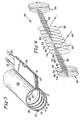
- a coil structure 2 consists of a first series of conductive rings 4, 6, 8 and 10 and a second series of conductive rings, 4', 6', 8' and 10'.
- the number of conductive rings and width of conductors illustrated are exemplary only, the number of rings and width employed in any specific application being a function of the length of the members to be treated and the current to be carried.
- Conductive rings 4 and 4' are interconnected by conductor 12
- conductive rings 6 and 6' are interconnected by conductor 14
- conductive rings 8 and 8' by conductor 16
- conductive rings 10 and 10' by conductor 18. All of the interconnections discussed above are of the ends of the conductive rings visible in Figure 1.
- the ends of the conductive rings not visible in Figure 1 are interconnected by conductors 12', 14' and 16' as illustrated in Figure 2 of the accompanying drawings.
- the lower end as illustrated in Figure 1 of conductive ring 4 is connected via a conductor 20 to one terminal of a source of alternating current (not illustrated).
- the end of the conductive ring 10' is connected via a conductor 22 to the other terminal of the aforesaid source of alternating current.
- Figure 2 the structure of Figure 1 is achieved by winding a flat spiral (pancake coil) starting with member 4 and winding a rectangular spiral ending with center conductor 22.
- the center conductor is folded at 90° to the elongated dimension of the conductors 4, 4', etc. to provide the lead 22 and to divide the conductive members into two groups, providing space air gap 24 of Figure 1.
- Conductor 20 forming a continuation of conductor 4 is parallel to conductor 22 in its folded position as illustrated clearly in Figure 2.
- the conductors 12, 14, 16 and 18 are folded over top of conductors 12', 14', 16' and 18' while the conductors 4, 6, 8, 10, 4', 6', 8' and 10' are formed into the corresponding conductive rings.
- the currents in the rings produce out-of-phase fields interiorly thereof.
- the air gap or space 24 substantially isolates the fields produced by the two coils thus forming two out-of-phase, low emitting solenoids with the crossover members 12, 14, 16 and 18 cancelling the field produced by the crossover members (not illustrated) and the fields of the members 20 and 22 also cancelling one another, while the fields external to the rings are quite weak as is the case in most solenoid configurations.
- FIG. 3 of the accompanying drawings there is illustrated a clamshell incorporating the coil structure of Figure 1.
- the coil structure 2 of Figure 1 is secured interiorly of a clamshell 23 comprised of two half sections 25 and 27 (jaws) hinged to one another by a hinge 29.
- the coil structure 2 as represented by conductive members 4, 6, 8 and 10, is secured interiorly of the clamshell and since the conductive members are quite thin they flex when the members 25 and 27 are rotated about hinge 29 to open the clamshell so as to permit side entry of a heater (a load) into the opened jaws.
- the jaws 25 and 27 have outwardly extending parallel flat surfaces or lips 31 and 33 disposed over (enclosing) the members 12, 14, 16, 18, 12', 14', 16' and 18' open the basic coil structure.
- the lips 31 and 33 are clamped closed by a latch 35 once the load is inserted and the jaws are closed.
- Coil structure 26 includes four coils 28, 30 32 and 34 with coils 28 and 30 interconnected by wires 36 and coils 32 and 34 interconnected by wires 38.
- Turn 40 of coil 30 has one end connected via lead 42 of the wires 36 to a turn 44 of coil 28.
- a wire 46 is connectable to a source of alternating current (not illustrated) and is connected to the end of the turn 40 not connected to lead 42.
- Turns 48, 50 and 52 are connected to one end of turns 54, 56 and 58 respectively, by leads 60, 62 and 64 and the other end of turns 44, 54 and 56 are connected by leads of bundle of wires 36 to turns 48, 50 and 52.
- the other end of turn 58 is connected to one end of a lower arc of turn 52 which crosses over and connects to turn 66 of coil 32.
- the pattern of interconnections of coils 32 and 34 is a mirror image of the interconnections between coils 28 and 30 with one end of a turn 68 closest to coil 34 being connected to a second terminal of a power
- the pattern of electromagnetic radiation from this coil structure both with and without the coils 28 and 34 is illustrated by the graphs of Figure 5. It is noted without coils 28 and 34, the level of radiation transmitted outwardly from the coils begins to exceed the radiation with the coils 28 and 34. The change in level begins to become significant at 0.3 inch from the center of the coil structure and at 0.5 inch the radiation with coils 28 and 34 is down 100 H/I from the structure without coils 28 and 34. This drop-off results from "cube" drop-off. It should be noted from Figure 5 that the coils 28 and 34 are located 0.5 inch from the junction of coils 30 and 32, the center of the structure.
- the coils 30 and 32 are placed over the ferromagnetic material to be heated, that is, the heater, and preferably the field produced by the coil is sufficient to cause the ferromagnetic material to be heated to approximately its effective Curie temperature if Curie temperature regulation is desired. If desired, the coils 28 and 34 may also be employed to energize the heater and other heaters.
- FIG. 6 and 7 there is illustrated a flat version of the coil structure of Figure 4 for use in griddles in, for instance, the fast food industry.
- the structure includes a ferromagnetic plate 60 forming the surface of the heated griddle.
- the coil structure of the present invention is element 62 and the intermediate layers are structure elements holding the various elements together.
- FIG. 7 A four cell arrangement is illustrated in Figure 7.
- Four cells or rectangular pancake coils 64, 66, 68 and 70 are interconnected in the same manner as the cylindrical coils of Figure 4.
- Coil 64 has an outermost turn 72 connected to outermost turn 74 of coil 66.
- Outermost turn 76 of coil 68 is connected to outermost turn 78 of coil 70.
- a current supply 80 is connected across ends 82 and 84 of the innermost turns of coils 64 and 70, respectively.
- the ends 86 and 88 of the innermost turns of coils 66 and 68, respectively, are connected together by lead 69.
- FIG. 8 A two coil arrangement of a pancake version of Figure 4 is illustrated in Figure 8.
- Two flat coils 90 and 92 have their outermost coils 94 and 96, respectively, connected together and ends 98 and 100 of innermost turns 102 and 104 connected across an ac source 106. Once again the current flows in the adjacent coils are in the opposite directions.
- the "rectangular" coil is the prior art single coil. Coil type Distance of a loop antenna from coil plate array d-15'' d-30'' perp. parallel prep. parallel Rectangular 20 mV 200 mV 4 mV 38 mV Rectangular with two cells (Figure 8) 9 mV 43 mV 1.6 mV 3.2 mV Rectangular with four cells ( Figure 7) 2 mV 1.8 mV 1 mV 1 mV 1 mV
- the frequency of the current preferably is 13.56 MHz but other frequencies may be employed with excellent results.
- ferromagnetic is employed herein to include any materials whose resistance reduces materially with temperature and includes without limitation ferromagnetics, ferrimagnetics and ferrites.
Abstract
Solenoid coils are provided that produce relatively low irradiation of electromagnetic fields with intense fields internally thereof for purposes of heating a metallic element, preferably a ferromagnetic element having a Curie temperature selected for the purpose for which the coil structure is to be employed, the coil structure in one embodiment comprising two coaxial coils of substantially equal diameter interconnected to produce in response to an alternating current being applied thereto out of phase magnetic fields that do not substantially interfere with one another as a result of the spacing between the coils. In a second embodiment the two coils are located between two additional coils that buck axial fields thereby together with fall off of the fields as the cube of the distance from the main coils provide a structure with low external radiation. The method of forming the first coil structure includes winding a pancake coil in the form of a spiral, rotating out of the plane of the coil the innermost leg of the spiral to provide the desired spacing of the coils, forming the pancake into a cylindrical shape with the cross members of the pancake being laid one over the other to provide cancellation of the fields produced by these members.
Description
- The present invention provides a method of fabricating and a structure including a hollow arcuate induction heating coil that produces low external radiation and more particularly to such a coil formed from a flat helically wound coil and a coil structure employing end coils to reduce radiation from interior coils.
- There are numerous induction coil structures in the induction heating and baking fields as well as the field of plastic pipe fusion such as exemplified in the latter case by U.S. Patent No. 5,125,690; International Publication Nos. WO81/02405 and WO82/02593 and WO82/02124 in addition to U.S. Serial No. 07/657,996 filed February 20, 1991 entitled "System and Method for Joining Plastic Materials"; U.S. Serial No. 07/776,378 filed January 24, 1992 entitled "Electro-Fusion Fitting"; and U.S. Serial No. 07/915,849 filed July 29, 1992 entitled "Electro-Fusion Fitting". The general theme of all of these applications and the patent is to employ a coil to inductively heat an element disposed between plastic members to be joined so as to heat the element; a metallic material, preferably a material such as a ferromagnetic material, that has its magnetic permeability materially reduced as a function of an increase of temperature beyond a threshold temperature. The threshold temperature is one which closely approaches the effective Curie temperature of the material. Such material in the references cited above is located in each instance between the members to be joined.
- Although the coils of the references are effective to some extent to accomplish the intended results, external radiation of magnetic flux is now recognized as a problem; particularly so as the knowledge of damage that can be caused by such external radiation increases.
- It is amongst the objects of the invention to provide coil structures having low magnetic field radiation external to the coil.
- It is another object of the present invention to provide an essentially hollow cylindrical coil structure that concentrates the magnetic field induced by an alternating electric current applied thereto interiorly of the coil and produces relatively little external magnetic radiation.
- It is still another object of the present invention to provide a method of producing a magnetic coil that radiates a relatively low magnetic field external to the coil.
- Yet another object of the present invention is to improve the overall level of emissions generated by induction cooking equipment for both the far field and near field conditions.
- The coil of the present invention includes in one preferred embodiment, two series of conductive rings being coaxial but spaced from one another. The rings are in the general form of a hollow cylinder with a second end of each ring of one series joined to a second end of a first ring of the other series of equal rank along the axis by a second conductor extending parallel to the axis of the cylinder and the first end of the ring of the other series joined to a first end of a second ring of the first series by a first conductor of a series of such conductors. The conductors interconnecting the conductive rings are in an overlapping array so as to buck each other's field, a plane intersecting them being remote from the axis of the cylinder. The interconnection of rings is outermost rings joined and remaining rings following in sequence the same order.
- In this manner the magnetic fields produced by the structure rings of the two series are out of phase with one another interiorly of the cylindrical rings. As a result of the space between the coils, the fields interiorly of the rings are intense while the usual advantages of a solenoid relative to external radiation are retained. Also the fields produced by the two sets of conductors interconnecting the rings of the two series since the current therein flow in opposite directions buck one another materially reducing radiation from these conductors.
- The coil structure described above may be fabricated by winding a rectangular pancake spiral of conductors with the unconnected end of the outermost conductor connectable to a first terminal of a source of alternating current and the unconnected end of the innermost conductor turned outwardly at its connected end to provide a space between two sets of conductors and a member to be connected to a second terminal of a source of alternating current. To form the coil described above the ends of the turns are overlapped as the cylindrical turns are formed thereby providing the conductors interconnecting the cylindrical conductors.
- In another embodiment, essentially the same effect as the above-described arrangement is achieved with the same basic arrangement of the cylindrical coils but the interconnection of the two series of conductor rings is effected by two coils one lying at but spaced from each end of the two series of rings. All interconnections between the conductive rings of one series are affected by connection through, on a one-for-one basis, the turns of the adjacent coils. The desired effect results from cube drop off, i.e., the field drops off as the cube of the distance from the ends of the coils.
- A flat pancake version with a four rectangular coil arrangement may be employed in commercial griddles, for instance, for fast food establishments. As in the circular version there are an even number of coils with adjacent coils oriented so that current in adjacent cells flows in opposite directions, the coils being substantially abutting each other in a two coil by two coil array. The shape aspect ratio of the individual cells in a particular design may vary, specifically, the individual coils may be of the same shape and identical or different aspect ratios or they may be of both different shapes and aspect ratios.
- The invention will now be described by way of example with reference to the accompanying drawings in which:-
- Figure 1 illustrates the coil structure of the preferred embodiment of the present invention;
- Figure 2 illustrates a flat spiral from which the coil structure of Figure 1 may be fabricated;
- Figure 3 illustrates the coil structure of the present invention in a clamshell;
- Figure 4 illustrates an alternative coil structure in accordance with the present invention;
- Figure 5 is a graph of the Henries/per ampere per meter as a function of location from center of the coil structure of Figure 4;
- Figure 6 is a side view of a griddle employing a ferromagnetic heating surface and a pancake coil arrangement as illustrated in Figure 7;
- Figure 7 is a top view of the coil structure employed in Figure 6; and
- Figure 8 is a two coil version of the coil version of Figure 7.
- Referring specifically to Figure 1 of the accompanying drawings, a
coil structure 2 consists of a first series ofconductive rings Conductive rings 4 and 4' are interconnected byconductor 12,conductive rings 6 and 6' are interconnected byconductor 14,conductive rings 8 and 8' byconductor 16 andconductive rings 10 and 10' byconductor 18. All of the interconnections discussed above are of the ends of the conductive rings visible in Figure 1. The ends of the conductive rings not visible in Figure 1 are interconnected by conductors 12', 14' and 16' as illustrated in Figure 2 of the accompanying drawings. - The lower end as illustrated in Figure 1 of
conductive ring 4 is connected via aconductor 20 to one terminal of a source of alternating current (not illustrated). The end of the conductive ring 10' is connected via aconductor 22 to the other terminal of the aforesaid source of alternating current. - The pattern of current flow in the conductive rings and conductors is as illustrated by arrows in Figure 1, such flow being obvious from the basic configuration of the structure as illustrated in Figure 2.
- Referring to Figure 2, the structure of Figure 1 is achieved by winding a flat spiral (pancake coil) starting with
member 4 and winding a rectangular spiral ending withcenter conductor 22. The center conductor is folded at 90° to the elongated dimension of theconductors 4, 4', etc. to provide thelead 22 and to divide the conductive members into two groups, providingspace air gap 24 of Figure 1.Conductor 20 forming a continuation ofconductor 4 is parallel toconductor 22 in its folded position as illustrated clearly in Figure 2. - To form the structure of Figure 1 from the structure of Figure 2, the
conductors conductors - It is noted that in all positions of the rings the currents in the rings produce out-of-phase fields interiorly thereof. The air gap or
space 24 substantially isolates the fields produced by the two coils thus forming two out-of-phase, low emitting solenoids with thecrossover members members - Referring to Figure 3 of the accompanying drawings, there is illustrated a clamshell incorporating the coil structure of Figure 1. The
coil structure 2 of Figure 1 is secured interiorly of aclamshell 23 comprised of twohalf sections 25 and 27 (jaws) hinged to one another by ahinge 29. As indicated, thecoil structure 2 as represented byconductive members members hinge 29 to open the clamshell so as to permit side entry of a heater (a load) into the opened jaws. - The
jaws lips members lips latch 35 once the load is inserted and the jaws are closed. - Referring specifically to Figure 4 of the accompanying drawings, there is provided an alternative coil structure for producing low electromagnetic radiations external to the coil.
-
Coil structure 26 includes fourcoils coils wires 36 andcoils wires 38. Turn 40 ofcoil 30 has one end connected vialead 42 of thewires 36 to aturn 44 ofcoil 28. Awire 46 is connectable to a source of alternating current (not illustrated) and is connected to the end of theturn 40 not connected tolead 42.Turns turns leads turns wires 36 to turns 48, 50 and 52. The other end ofturn 58 is connected to one end of a lower arc ofturn 52 which crosses over and connects toturn 66 ofcoil 32. The pattern of interconnections ofcoils coils turn 68 closest tocoil 34 being connected to a second terminal of a power supply. - The pattern of electromagnetic radiation from this coil structure both with and without the
coils coils coils coils coils coils coils - In use, normally the
coils coils - Referring now specifically to Figures 6 and 7 there is illustrated a flat version of the coil structure of Figure 4 for use in griddles in, for instance, the fast food industry.
- The structure includes a
ferromagnetic plate 60 forming the surface of the heated griddle. The coil structure of the present invention iselement 62 and the intermediate layers are structure elements holding the various elements together. - The details of the coil structure are illustrated in Figure 7. It has been determined that the unwanted emissions generated by induction heating equipment can be considerably diminished if the coil that couples the electromagnetic field to the ferromagnetic load is designed as an array of an even number of cells, oriented in such a way that adjacent cells generate electromagnetic fields with opposite directions.
- A four cell arrangement is illustrated in Figure 7. Four cells or rectangular pancake coils 64, 66, 68 and 70 are interconnected in the same manner as the cylindrical coils of Figure 4.
Coil 64 has anoutermost turn 72 connected tooutermost turn 74 ofcoil 66.Outermost turn 76 ofcoil 68 is connected tooutermost turn 78 ofcoil 70. Acurrent supply 80 is connected across ends 82 and 84 of the innermost turns ofcoils coils lead 69. Thus the currents flowing in each coil is in a direction opposite to that of the two coils adjacent thereto. Therefore this arrangement is the same so far as current flows are concerned as the coil structure of Figure 4. - A two coil arrangement of a pancake version of Figure 4 is illustrated in Figure 8. Two
flat coils outermost coils innermost turns ac source 106. Once again the current flows in the adjacent coils are in the opposite directions. - In the chart below the intensity of the magnetic fields measure 15'' and 30'' away from the 2 and 4 coil arrays as displayed. The "rectangular" coil is the prior art single coil.
Coil type Distance of a loop antenna from coil plate array d-15'' d-30'' perp. parallel prep. parallel Rectangular 20 mV 200 mV 4 mV 38 mV Rectangular with two cells (Figure 8) 9 mV 43 mV 1.6 mV 3.2 mV Rectangular with four cells (Figure 7) 2 mV 1.8 mV 1 mV 1 mV - Thus it is shown that the coil arrangement of Figures 7 and 8 are effective in reducing magnetic radiation, particularly the four coil array.
- The frequency of the current preferably is 13.56 MHz but other frequencies may be employed with excellent results. The term "effective Curie temperature" relates to the temperature at which there is a marked decrease in the permeability, a decrease sufficient to reduce the heating so that the hater begins to cool and again becomes ferromagnetic. Such temperature may be 1°C to 100°C less than the absolute Curie temperature depending upon the ferromagnetic material used. If Curie point temperature control is to be employed a constant current power supply is preferred so that the standard P=I²R becomes P=KR so that when effective Curie temperature is reached and the factor R decreases heating is decreased. As previously indicated the term "ferromagnetic" is employed herein to include any materials whose resistance reduces materially with temperature and includes without limitation ferromagnetics, ferrimagnetics and ferrites.
Claims (7)
- A griddle comprising
enerally flat ferromagnetic plate,
a flat coil structure generally parallel to and electrically insulated from said ferromagnetic plate,
said coil structure including at least two flat, spiral coils disposed side by side, and
means interconnecting said coils so that currents in said coils flow in opposite directions. - A griddle according to claim 1 wherein
said coil structure includes four coils in a two by two array,
said coils interconnected such that current in each coil flows in a direction opposite to both adjacent coils. - A flat pancake coil structure comprising
an even number of flat rectangular pancake coils of an equal number of turns;
said coils abutting one another,
said turns being in rectangular spiral form with a length of an outermost turn of each of two abutting coils being common to both said abutting coils,
said common outermost length interconnecting said coils such that current flows in opposite directions in said coils. - A pancake coil according to claim 3 wherein there are four such coils arranged in squares.
- A pancake coil according to claim 3 further comprising
means for connecting a source of current to innermost ends of adjacent coils. - A flat pancake coil structure comprising
an even number of flat rectangular pancake coils of an equal number of turns,
said turns being in a rectangular spiral configuration,
each said coil having an outer turn of the spiral of each coil abutting one another over their lengths and electrically interconnected such that the current flowing in each flows in the same direction. - A flat pancake coil structure comprising
four rectangular coils arranged in a generally square configuration,
said square configuration comprising two groups of two interconnected coils abutting one another such that all abutting turns have the current flowing therein in the same direction,
the innermost turn of one coil of each group being interconnected, and
an innermost turn of a different coil of each group having means to connect the coils across a source of alternating current.
Applications Claiming Priority (2)
| Application Number | Priority Date | Filing Date | Title |
|---|---|---|---|
| US07/974,734 US5304767A (en) | 1992-11-13 | 1992-11-13 | Low emission induction heating coil |
| US974734 | 1992-11-13 |
Publications (1)
| Publication Number | Publication Date |
|---|---|
| EP0602797A1 true EP0602797A1 (en) | 1994-06-22 |
Family
ID=25522385
Family Applications (2)
| Application Number | Title | Priority Date | Filing Date |
|---|---|---|---|
| EP93309009A Expired - Lifetime EP0599519B1 (en) | 1992-11-13 | 1993-11-11 | Low emission induction heating coil |
| EP93309008A Withdrawn EP0602797A1 (en) | 1992-11-13 | 1993-11-11 | Low emission induction heating coil |
Family Applications Before (1)
| Application Number | Title | Priority Date | Filing Date |
|---|---|---|---|
| EP93309009A Expired - Lifetime EP0599519B1 (en) | 1992-11-13 | 1993-11-11 | Low emission induction heating coil |
Country Status (5)
| Country | Link |
|---|---|
| US (2) | US5304767A (en) |
| EP (2) | EP0599519B1 (en) |
| JP (2) | JPH06243961A (en) |
| CA (2) | CA2102950C (en) |
| DE (2) | DE69319311D1 (en) |
Cited By (2)
| Publication number | Priority date | Publication date | Assignee | Title |
|---|---|---|---|---|
| AT5955U3 (en) * | 1994-10-09 | 2003-07-25 | Wuest Ernst Menu System | COOKER |
| DE102007025690A1 (en) * | 2007-06-01 | 2008-12-04 | Hpf Gmbh | Method and arrangement for heating a medium in an elongate container, in particular in a tubular liquid supply line |
Families Citing this family (70)
| Publication number | Priority date | Publication date | Assignee | Title |
|---|---|---|---|---|
| JP3141562B2 (en) * | 1992-05-27 | 2001-03-05 | 富士電機株式会社 | Thin film transformer device |
| US5786575A (en) * | 1995-12-20 | 1998-07-28 | Gas Research Institute | Wrap tool for magnetic field-responsive heat-fusible pipe couplings |
| FR2748885B1 (en) * | 1996-05-14 | 1998-08-14 | Europ Equip Menager | HIGH EFFICIENCY INDUCTION COOKING FIREPLACE |
| FR2792158B1 (en) * | 1999-04-09 | 2001-05-18 | Jaeger Regulation | MODULAR INDUCTION COOKING FIREPLACE WITH REDUCED RADIATION AND METHOD OF MAKING |
| US6528770B1 (en) | 1999-04-09 | 2003-03-04 | Jaeger Regulation | Induction cooking hob with induction heaters having power supplied by generators |
| US6753515B2 (en) * | 2000-04-28 | 2004-06-22 | Ricoh Company, Ltd. | Induction heating type fixing device for an image forming apparatus and induction heating coil therefor |
| US6396454B1 (en) * | 2000-06-23 | 2002-05-28 | Cue Corporation | Radio unit for computer systems |
| JP4545899B2 (en) * | 2000-07-31 | 2010-09-15 | キヤノン株式会社 | Heating apparatus and image forming apparatus |
| US6555801B1 (en) | 2002-01-23 | 2003-04-29 | Melrose, Inc. | Induction heating coil, device and method of use |
| GB0213375D0 (en) * | 2002-06-10 | 2002-07-24 | Univ City Hong Kong | Apparatus for energy transfer by induction |
| EP1404155B1 (en) * | 2002-09-26 | 2005-12-14 | MTECH Holding AB | Inductive frying hob arrangement |
| US20040084443A1 (en) * | 2002-11-01 | 2004-05-06 | Ulrich Mark A. | Method and apparatus for induction heating of a wound core |
| JP2004207700A (en) * | 2002-12-11 | 2004-07-22 | Canon Inc | Electronic component and method for manufacturing the same |
| TWM249190U (en) * | 2003-12-26 | 2004-11-01 | Hung-Wen Lin | Laminated chip inductor structure |
| US20100301037A1 (en) * | 2004-03-03 | 2010-12-02 | Wuest Ernst | Food treating device |
| FR2895638B1 (en) * | 2005-12-27 | 2008-04-18 | Brandt Ind Sas | INDUCING DEVICE WITH MULTIPLE INDIVIDUAL WINDINGS FOR INDUCTION COOKING FIREPLACE |
| CN2930548Y (en) * | 2006-07-13 | 2007-08-08 | 厦门灿坤实业股份有限公司 | Milk automatic foaming device |
| US7989012B2 (en) * | 2007-09-26 | 2011-08-02 | Kellogg Company | Induction cooking structure and system and method of using the same |
| US8065999B2 (en) * | 2008-07-14 | 2011-11-29 | W.C. Bradley Co. | Adjustable cooking grate for barbeque grills |
| JP5227832B2 (en) * | 2009-02-23 | 2013-07-03 | 三菱電機株式会社 | Induction heating cooker |
| US8133384B2 (en) * | 2009-03-02 | 2012-03-13 | Harris Corporation | Carbon strand radio frequency heating susceptor |
| US8101068B2 (en) * | 2009-03-02 | 2012-01-24 | Harris Corporation | Constant specific gravity heat minimization |
| US8887810B2 (en) * | 2009-03-02 | 2014-11-18 | Harris Corporation | In situ loop antenna arrays for subsurface hydrocarbon heating |
| US8128786B2 (en) * | 2009-03-02 | 2012-03-06 | Harris Corporation | RF heating to reduce the use of supplemental water added in the recovery of unconventional oil |
| US8729440B2 (en) | 2009-03-02 | 2014-05-20 | Harris Corporation | Applicator and method for RF heating of material |
| US9034176B2 (en) | 2009-03-02 | 2015-05-19 | Harris Corporation | Radio frequency heating of petroleum ore by particle susceptors |
| US8674274B2 (en) * | 2009-03-02 | 2014-03-18 | Harris Corporation | Apparatus and method for heating material by adjustable mode RF heating antenna array |
| US8120369B2 (en) * | 2009-03-02 | 2012-02-21 | Harris Corporation | Dielectric characterization of bituminous froth |
| US8494775B2 (en) * | 2009-03-02 | 2013-07-23 | Harris Corporation | Reflectometry real time remote sensing for in situ hydrocarbon processing |
| KR101535145B1 (en) * | 2009-05-04 | 2015-07-08 | 엘지전자 주식회사 | Cooker and controlling method thereof |
| JP2011018511A (en) * | 2009-07-08 | 2011-01-27 | Nakai:Kk | Electromagnetic induction heater |
| DE102009040825A1 (en) * | 2009-09-10 | 2011-03-24 | Sms Elotherm Gmbh | Inductor and use of such an inductor |
| TW201123993A (en) * | 2009-12-24 | 2011-07-01 | Delta Electronics Inc | Coil fixing unit and assembly structure of coil fixing unit and coil |
| KR101404386B1 (en) * | 2010-01-06 | 2014-06-09 | 신닛테츠스미킨 카부시키카이샤 | Induction heating coil, device for manufacturing of workpiece, and manufacturing method |
| JP5444134B2 (en) * | 2010-06-18 | 2014-03-19 | 東京電力株式会社 | Stator heating method and apparatus using induction heating |
| US8648760B2 (en) | 2010-06-22 | 2014-02-11 | Harris Corporation | Continuous dipole antenna |
| US8695702B2 (en) | 2010-06-22 | 2014-04-15 | Harris Corporation | Diaxial power transmission line for continuous dipole antenna |
| US8450664B2 (en) | 2010-07-13 | 2013-05-28 | Harris Corporation | Radio frequency heating fork |
| US8763691B2 (en) | 2010-07-20 | 2014-07-01 | Harris Corporation | Apparatus and method for heating of hydrocarbon deposits by axial RF coupler |
| US8772683B2 (en) | 2010-09-09 | 2014-07-08 | Harris Corporation | Apparatus and method for heating of hydrocarbon deposits by RF driven coaxial sleeve |
| US8692170B2 (en) | 2010-09-15 | 2014-04-08 | Harris Corporation | Litz heating antenna |
| US8646527B2 (en) | 2010-09-20 | 2014-02-11 | Harris Corporation | Radio frequency enhanced steam assisted gravity drainage method for recovery of hydrocarbons |
| US8789599B2 (en) | 2010-09-20 | 2014-07-29 | Harris Corporation | Radio frequency heat applicator for increased heavy oil recovery |
| US8511378B2 (en) | 2010-09-29 | 2013-08-20 | Harris Corporation | Control system for extraction of hydrocarbons from underground deposits |
| US8373516B2 (en) | 2010-10-13 | 2013-02-12 | Harris Corporation | Waveguide matching unit having gyrator |
| US8616273B2 (en) | 2010-11-17 | 2013-12-31 | Harris Corporation | Effective solvent extraction system incorporating electromagnetic heating |
| US8453739B2 (en) | 2010-11-19 | 2013-06-04 | Harris Corporation | Triaxial linear induction antenna array for increased heavy oil recovery |
| US8763692B2 (en) | 2010-11-19 | 2014-07-01 | Harris Corporation | Parallel fed well antenna array for increased heavy oil recovery |
| US8443887B2 (en) | 2010-11-19 | 2013-05-21 | Harris Corporation | Twinaxial linear induction antenna array for increased heavy oil recovery |
| US9844100B2 (en) | 2011-03-25 | 2017-12-12 | Raleigh C. Duncan | Electromagnetic wave reducing heater |
| US8877041B2 (en) | 2011-04-04 | 2014-11-04 | Harris Corporation | Hydrocarbon cracking antenna |
| TWI410986B (en) * | 2011-05-23 | 2013-10-01 | 矽品精密工業股份有限公司 | Differential symmetrical inductor |
| JP5812486B2 (en) * | 2011-10-06 | 2015-11-11 | 国立研究開発法人海洋研究開発機構 | Fusing equipment |
| CN103573247B (en) * | 2012-07-20 | 2019-05-17 | 中国石油集团长城钻探工程有限公司 | Induction logging parallel plane coil and induction logging equipment |
| JP5900274B2 (en) * | 2012-10-04 | 2016-04-06 | トヨタ車体株式会社 | Induction heating dryer |
| TWI495399B (en) * | 2013-03-08 | 2015-08-01 | Delta Electronics Inc | Electromagnetic induction heater capable of increasing range of heating |
| JP5842183B2 (en) * | 2013-05-20 | 2016-01-13 | パナソニックIpマネジメント株式会社 | Induction heating device |
| US10765597B2 (en) | 2014-08-23 | 2020-09-08 | High Tech Health International, Inc. | Sauna heating apparatus and methods |
| US10243411B2 (en) * | 2014-09-18 | 2019-03-26 | Qualcomm Incorporated | Wireless charger with uniform H-field generator and EMI reduction |
| CN104684126B (en) * | 2015-02-17 | 2017-03-01 | 沈阳工业大学 | The electromagnetic induction heating coil of distance adjustable |
| DE102015214666A1 (en) * | 2015-07-31 | 2017-02-02 | TRUMPF Hüttinger GmbH + Co. KG | Inductor and inductor arrangement |
| DE102016120049A1 (en) * | 2016-10-20 | 2018-04-26 | Ke-Kelit Kunststoffwerk Gmbh | Inductive welding of plastic objects by means of a coil arrangement with several individual coils |
| US11665790B2 (en) * | 2016-12-22 | 2023-05-30 | Whirlpool Corporation | Induction burner element having a plurality of single piece frames |
| US11039508B2 (en) * | 2017-05-19 | 2021-06-15 | Spring (U.S.A.) Corporation | Induction range |
| US11219101B2 (en) * | 2018-05-03 | 2022-01-04 | Haier Us Appliance Solutions, Inc. | Induction cooking appliance having multiple heating coils |
| ES2736077A1 (en) * | 2018-06-21 | 2019-12-23 | Bsh Electrodomesticos Espana Sa | Induction oven device (Machine-translation by Google Translate, not legally binding) |
| JP7290858B2 (en) * | 2019-04-02 | 2023-06-14 | 富士電子工業株式会社 | induction heating coil |
| US20200374989A1 (en) * | 2019-05-23 | 2020-11-26 | Spring (U.S.A.) Corporation | Induction Heating Surface |
| BR112022019039A2 (en) * | 2020-03-24 | 2022-11-01 | Midrex Technologies Inc | METHOD AND SYSTEM FOR HEATING DIRECT REDUCED IRON BETWEEN A DIRECT REDUCED IRON SOURCE AND PROCESSING EQUIPMENT FOR DIRECT REDUCED IRON, AND SUPPLY CONDUIT HEATER ASSEMBLY |
| CN111575448B (en) * | 2020-06-16 | 2021-10-22 | 广西汇恒机械制造有限公司 | Processing method of shaft |
Citations (5)
| Publication number | Priority date | Publication date | Assignee | Title |
|---|---|---|---|---|
| FR2481042A1 (en) * | 1980-04-18 | 1981-10-23 | Electricite De France | Cooker plates induction heating coils - comprise two mirror image bean-shaped coils with current circulating in opposite senses to improve heat distribution |
| GB2199720A (en) * | 1986-12-10 | 1988-07-13 | Electricite De France | Electric induction cooking appliances with reduced harmonic emission |
| DE3704581A1 (en) * | 1987-02-13 | 1988-09-15 | Thomson Brandt Gmbh | Cooker having inductively heated hotplates |
| EP0283859A2 (en) * | 1987-03-19 | 1988-09-28 | Thomson Electromenager S.A. | Coil arrangement, manufacturing process of pairs of coils and manufacturing device of pairs of coils |
| EP0442219A1 (en) * | 1990-02-16 | 1991-08-21 | Metcal Inc. | Rapid uniformly heating, highly efficient griddle |
Family Cites Families (27)
| Publication number | Priority date | Publication date | Assignee | Title |
|---|---|---|---|---|
| US2052010A (en) * | 1934-08-04 | 1936-08-25 | Chrysler Corp | Induction heating apparatus |
| US2452801A (en) * | 1944-06-07 | 1948-11-02 | Sunbeam Corp | Apparatus for high-frequency induction heating |
| US2480299A (en) * | 1946-05-16 | 1949-08-30 | Air Reduction | Apparatus for butt welding with induction heating |
| US2641682A (en) * | 1949-04-04 | 1953-06-09 | Kennametal Inc | Induction heating unit |
| US2756313A (en) * | 1953-07-08 | 1956-07-24 | Tung Sol Electric Inc | High frequency induction heater |
| US3038055A (en) * | 1958-03-31 | 1962-06-05 | Ajax Magnethermic Corp | Inductors for seam welding |
| CA851846A (en) * | 1965-08-31 | 1970-09-15 | Viart Fernand | Process and means for heating by induction |
| US3424886A (en) * | 1966-10-27 | 1969-01-28 | Ajax Magnethermic Corp | Induction heating |
| US3688233A (en) * | 1971-03-12 | 1972-08-29 | Westinghouse Electric Corp | Electrical inductive apparatus having serially interconnected coils |
| US3688236A (en) * | 1971-03-12 | 1972-08-29 | Westinghouse Electric Corp | Electrical inductive apparatus having serially interconnected windings |
| US3725630A (en) * | 1971-12-20 | 1973-04-03 | Cycle Dyne Inc | Inductive coil for heating a loop of conductive material |
| US3755644A (en) * | 1972-06-27 | 1973-08-28 | Growth Int Inc | High frequency induction heating apparatus |
| GB1446737A (en) * | 1972-11-15 | 1976-08-18 | Matsushita Electric Ind Co Ltd | Induction cooking appliances |
| US4010536A (en) * | 1973-04-04 | 1977-03-08 | Toshio Fujita | Method of adjusting two concentric windings in electrical induction devices |
| US4145591A (en) * | 1976-01-24 | 1979-03-20 | Nitto Chemical Industry Co., Ltd. | Induction heating apparatus with leakage flux reducing means |
| AT365027B (en) * | 1976-07-26 | 1981-12-10 | Stahlcord Ges M B H & Co Kg | METHOD FOR THE THERMAL SURFACE TREATMENT OF PARTICULARLY WIRE OR TAPE-BASED CARRIERS MADE OF FERROMAGNETIC MATERIAL |
| SE413716B (en) * | 1978-05-02 | 1980-06-16 | Asea Ab | POWER TRANSFORMER OR REACTOR |
| US4402309A (en) * | 1981-10-22 | 1983-09-06 | Donald L. Morton & Associates | Therapeutic magnetic electrode |
| US4629843A (en) * | 1984-04-11 | 1986-12-16 | Tdk Corporation | Induction cooking apparatus having a ferrite coil support |
| US4778971A (en) * | 1986-05-23 | 1988-10-18 | Kabushiki Kaisha Meidensha | Induction heating apparatus |
| FR2599482B1 (en) * | 1986-06-03 | 1988-07-29 | Commissariat Energie Atomique | HIGH FREQUENCY INDUCTION FUSION OVEN |
| GB2205720B (en) * | 1987-06-10 | 1991-01-02 | Electricity Council | Induction heater |
| US4959631A (en) * | 1987-09-29 | 1990-09-25 | Kabushiki Kaisha Toshiba | Planar inductor |
| FR2623691B1 (en) * | 1987-12-01 | 1990-03-09 | Electricite De France | APPARATUS FOR COOKING LOW THICKNESS DISHES SUCH AS OMELETTES, QUICHES OR THE LIKE |
| US5053593A (en) * | 1989-01-23 | 1991-10-01 | Nikko Corporation Ltd. | Low-frequency electromagnetic induction heater |
| US5125690A (en) * | 1989-12-15 | 1992-06-30 | Metcal, Inc. | Pipe joining system and method |
| US5194708A (en) * | 1990-08-24 | 1993-03-16 | Metcal, Inc. | Transverse electric heater |
-
1992
- 1992-11-13 US US07/974,734 patent/US5304767A/en not_active Expired - Lifetime
-
1993
- 1993-01-08 US US08/001,616 patent/US5376774A/en not_active Expired - Lifetime
- 1993-11-11 DE DE69319311A patent/DE69319311D1/en not_active Expired - Fee Related
- 1993-11-11 EP EP93309009A patent/EP0599519B1/en not_active Expired - Lifetime
- 1993-11-11 DE DE69319311T patent/DE69319311T4/en not_active Expired - Lifetime
- 1993-11-11 EP EP93309008A patent/EP0602797A1/en not_active Withdrawn
- 1993-11-12 CA CA002102950A patent/CA2102950C/en not_active Expired - Fee Related
- 1993-11-12 CA CA002102965A patent/CA2102965A1/en not_active Abandoned
- 1993-11-15 JP JP5308667A patent/JPH06243961A/en active Pending
- 1993-11-15 JP JP5308668A patent/JPH06243960A/en not_active Withdrawn
Patent Citations (5)
| Publication number | Priority date | Publication date | Assignee | Title |
|---|---|---|---|---|
| FR2481042A1 (en) * | 1980-04-18 | 1981-10-23 | Electricite De France | Cooker plates induction heating coils - comprise two mirror image bean-shaped coils with current circulating in opposite senses to improve heat distribution |
| GB2199720A (en) * | 1986-12-10 | 1988-07-13 | Electricite De France | Electric induction cooking appliances with reduced harmonic emission |
| DE3704581A1 (en) * | 1987-02-13 | 1988-09-15 | Thomson Brandt Gmbh | Cooker having inductively heated hotplates |
| EP0283859A2 (en) * | 1987-03-19 | 1988-09-28 | Thomson Electromenager S.A. | Coil arrangement, manufacturing process of pairs of coils and manufacturing device of pairs of coils |
| EP0442219A1 (en) * | 1990-02-16 | 1991-08-21 | Metcal Inc. | Rapid uniformly heating, highly efficient griddle |
Cited By (2)
| Publication number | Priority date | Publication date | Assignee | Title |
|---|---|---|---|---|
| AT5955U3 (en) * | 1994-10-09 | 2003-07-25 | Wuest Ernst Menu System | COOKER |
| DE102007025690A1 (en) * | 2007-06-01 | 2008-12-04 | Hpf Gmbh | Method and arrangement for heating a medium in an elongate container, in particular in a tubular liquid supply line |
Also Published As
| Publication number | Publication date |
|---|---|
| EP0599519A1 (en) | 1994-06-01 |
| US5376774A (en) | 1994-12-27 |
| US5304767A (en) | 1994-04-19 |
| CA2102950C (en) | 1996-10-29 |
| CA2102965A1 (en) | 1994-05-14 |
| JPH06243960A (en) | 1994-09-02 |
| DE69319311T2 (en) | 1999-02-25 |
| DE69319311D1 (en) | 1998-07-30 |
| EP0599519B1 (en) | 1998-06-24 |
| DE69319311T4 (en) | 2000-08-17 |
| JPH06243961A (en) | 1994-09-02 |
| CA2102950A1 (en) | 1994-05-14 |
Similar Documents
| Publication | Publication Date | Title |
|---|---|---|
| US5376774A (en) | Low emission induction heating coil | |
| CA1303104C (en) | High power self-regulating heater | |
| USRE36787E (en) | High power induction work coil for small strip susceptors | |
| US4453067A (en) | Induction heating coil | |
| JP3311391B2 (en) | Leakage inductance reducing transformer, high frequency circuit and power converter using the same, and method of reducing leakage inductance in transformer | |
| US5339061A (en) | Iron-free transformer | |
| US6369680B1 (en) | Transformer | |
| US5349165A (en) | Induction heater system for fusing plastics | |
| RU2072118C1 (en) | Induction heater for ferromagnetic material | |
| EP0295072B1 (en) | Induction heater | |
| EP0748577B1 (en) | Induction heating element | |
| US11224756B2 (en) | Magnetic field generating-apparatus for biostimulation | |
| US4812608A (en) | Oven for thermo-magnetic treatment of toroidal coils of amorphous ferro-magnetic ribbon material | |
| JP2939554B2 (en) | Induction cooker | |
| JP2873659B2 (en) | Uniform heating sheet for induction cooker | |
| CA1264796A (en) | High efficiency autoregulating heater | |
| EP0283859A3 (en) | Coil arrangement, manufacturing process of pairs of coils and manufacturing device of pairs of coils | |
| ES2284066T3 (en) | INDUCTOR WITH A ROLLED CORD FORMING A SPIRAL INDUCTION COIL. | |
| JPS62287591A (en) | Induction heating cooker | |
| JP3791976B2 (en) | High frequency heating device output transformer | |
| JPS636876Y2 (en) | ||
| JPH02220388A (en) | Heating device | |
| JP2697166B2 (en) | High frequency heating equipment | |
| CN110089199A (en) | Induction coil for induction heating utensil | |
| JPH08228912A (en) | Induction heating coil and induction heating rice cooker |
Legal Events
| Date | Code | Title | Description |
|---|---|---|---|
| PUAI | Public reference made under article 153(3) epc to a published international application that has entered the european phase |
Free format text: ORIGINAL CODE: 0009012 |
|
| AK | Designated contracting states |
Kind code of ref document: A1 Designated state(s): BE DE FR GB |
|
| 17P | Request for examination filed |
Effective date: 19941220 |
|
| 17Q | First examination report despatched |
Effective date: 19961216 |
|
| STAA | Information on the status of an ep patent application or granted ep patent |
Free format text: STATUS: THE APPLICATION IS DEEMED TO BE WITHDRAWN |
|
| 18D | Application deemed to be withdrawn |
Effective date: 19991122 |