EP0602639B1 - Rotor temperature control system - Google Patents
Rotor temperature control system Download PDFInfo
- Publication number
- EP0602639B1 EP0602639B1 EP93120317A EP93120317A EP0602639B1 EP 0602639 B1 EP0602639 B1 EP 0602639B1 EP 93120317 A EP93120317 A EP 93120317A EP 93120317 A EP93120317 A EP 93120317A EP 0602639 B1 EP0602639 B1 EP 0602639B1
- Authority
- EP
- European Patent Office
- Prior art keywords
- temperature
- rotor
- determining
- ambient
- operation factor
- Prior art date
- Legal status (The legal status is an assumption and is not a legal conclusion. Google has not performed a legal analysis and makes no representation as to the accuracy of the status listed.)
- Expired - Lifetime
Links
Images


Classifications
-
- B—PERFORMING OPERATIONS; TRANSPORTING
- B04—CENTRIFUGAL APPARATUS OR MACHINES FOR CARRYING-OUT PHYSICAL OR CHEMICAL PROCESSES
- B04B—CENTRIFUGES
- B04B15/00—Other accessories for centrifuges
- B04B15/02—Other accessories for centrifuges for cooling, heating, or heat insulating
-
- G—PHYSICS
- G05—CONTROLLING; REGULATING
- G05D—SYSTEMS FOR CONTROLLING OR REGULATING NON-ELECTRIC VARIABLES
- G05D23/00—Control of temperature
- G05D23/19—Control of temperature characterised by the use of electric means
- G05D23/27—Control of temperature characterised by the use of electric means with sensing element responsive to radiation
Definitions
- the present invention relates to a rotor temperature control system for a centrifuge as defined in the preamble of claim 1, and to a rotor temperature controlling method as defined in the preamble of claim 4.
- a system and a method of this kind are disclosed in GB-A-2 150 717. More particularly, the invention relates to a rotor temperature control system which is operable to modify an operation factor of a temperature regulating device based on an ambient temperature to control the temperature of a rotor in which samples to be separated are disposed to a target rotor temperature.
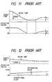
- a proportional control (P control), as shown in Fig. 10, has been proposed in the art which changes an operation factor of a temperature regulating device in proportion to an error E developing between an actual rotor temperature and a target rotor temperature.
- the proportional control also has been suffered from the following drawback.
- the moment the error E is reduced to zero, the operation factor is also set to zero.
- the rotor temperature rises above the target rotor temperature to produce a small error again since the target rotor temperature is usually set to a value lower than ambient temperatures and the temperature regulating device is warmed by the ambient air.
- the operation factor is increased again (e.g., several percentages D), however, the activities of elevating the rotor temperature and restricting same are balanced with each other, ultimately producing an error e .
- the so-called PI control using integral action (I action) along with the P control is known.
- the integral action is such that the error e is added in time-sequence to derive a correction value to correct the operation factor based thereon.
- an operation factor D corrected based on an integration value of the error e is provided to regulate the temperature of the rotor to a target rotor temperature.
- the operation factor of the temperature regulating device is changed in proportion to the error E between the actual rotor temperature and the target rotor temperature.
- the operation factor of the temperature regulating device is set to a greater value so that the rotor temperature reaches the target rotor temperature quickly.
- the operation factor of the temperature regulating device is set to a smaller value, undesirably requiring relatively long period of time for the rotor temperature to reach the target rotor temperature.
- a drawback in encountered in that the operation factor of the temperature regulating device is greatly dependent upon the degree of the temperature error between the rotor temperature and the target rotor temperature.
- GB-A-2 150 717 discloses a rotor temperature control system and a rotor temperature controlling method as defined in the preamble of claims 1 and 4, respectively.
- a cooling unit is used for cooling a rotor chamber.
- the actual temperature is monitored by means of a temperature sensor provided in the rotor chamber.
- the chamber temperature detected by means of the temperature sensor is compared in a control circuit with a predetermined reference temperature. If a temperature difference occurs, a solenoid valve is driven for controlling a coolant supply.
- a rotor temperature control system for a centrifuge which comprises an ambient temperature determining means for determining ambient temperature around the system to provide a signal indicative thereof, a temperature regulating means for regulating temperature of a rotor of the centrifuge according to an operation factor variable within a range of preselected maximum to minimum values, and a controlling means, responsive to the signal from the ambient temperature determining means, for controlling the operation factor of the temperature regulating means in a preselected relation to the ambient temperature and a given target rotor temperature to modify the temperature of the rotor to the target rotor temperature.
- a rotor temperature determining means is further provided which determines the temperature of the rotor and provides a signal indicative thereof.
- the controlling means operates the temperature regulating means at the operation factor determined in the preselected relation to the ambient temperature and the given target rotor temperature while monitoring a difference between the rotor temperature determined by the rotor temperature determining means and the target rotor temperature.
- the controlling means corrects the operation factor of the temperature regulating means determined in the preselected relation to the ambient temperature and the given target rotor temperature according to a correction value which is derived based on a difference between the rotor temperature determined by the rotor temperature determining means and the target rotor temperature.
- the temperature regulating means includes a heat radiating/absorbing means surrounding the rotor and a heat-exchanging means operable to transfer heat between ambient air and the heat radiating/absorbing means.
- the ambient temperature determining means monitors the temperature of the heat-exchanging means to determine the ambient temperature.
- the rotor temperature determining means includes a radiating temperature sensor which detects radiation heat produced from the rotor.
- the controlling means determines the rotor temperature based on the radiation heat from the rotor and the ambient temperature determined by the ambient temperature determining means.
- a rotor temperature controlling method for controlling temperature of a rotor of a centrifuge which comprises the steps of: determining ambient temperature around temperature regulating means for regulating temperature of the rotor according to an operation factor variable within a range of preselected maximum to minimum values; determining a value of the operation factor of the temperature regulating means in a preselected relation to the ambient temperature and a given target rotor temperature; and providing a control signal to the temperature regulating means to operate the temperature regulating means at the operation factor determined in the operation factor determining step for modifying the temperature of the rotor to the target rotor temperature.
- the rotor temperature controlling method further comprises the steps of determining temperature of the rotor and correcting the operation factor of the temperature regulating means determined in the preselected relation to the ambient temperature and the given target rotor temperature according to a correction value which is based on a difference between the rotor temperature determined by the rotor temperature determining means and the target rotor temperature.
- the temperature regulating means includes a heat radiating/absorbing means surrounding the rotor and a heat-exchanging means operable to transfer heat between ambient air and the heat radiating/absorbing means.
- the temperature of the heat-exchanging means is monitored to determine the ambient temperature.
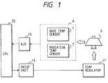
- the rotor temperature control system includes generally a rotor temperature detector 4, an A/D converter 18, a CPU 20, a drive unit 19, and a rotor temperature regulating assembly 17.
- the CPU 20 controls an operation factor of the rotor temperature regulating assembly 17 through the drive unit 19 based on a detection signal output from the rotor temperature detector 4 through the A/D converter.
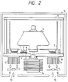
- the rotor temperature regulating assembly 17 includes a housing 16, a vacuum chamber 15, a bowl 7 surrounding the rotor 6, distance pieces or spacers 8 attached to the bowl 7, a radiating fin plate 10, thermoelectric cooling/heating elements 9 interposed between the spacers 8 and the radiating fin plate 10, respectively, radiating fins 11, and cooling fan 12 for cooling the radiating fins 11.
- thermoelectric cooling/heating elements 9 manifests properties which absorb heat of a quantity, according to a current applied thereto, through its surface and radiate the absorbed heat from the other surface.
- the rotor 6 in which samples are disposed is driven by a motor 14 at high speeds so that the samples are separated under centrifugal forces.
- the vacuum chamber 15 is maintained at high vacuum levels by a vacuum pump (not shown).
- the rotor temperature detector 4 includes a base temperature sensor 1, a radiation temperature sensor 2, a base plate 3, and a spacer 5.
- the base temperature sensor 1 is directly mounted on the base plate 3 to measure temperature thereof.
- the radiation temperature sensor 2 is so arranged on the base plate 3 as to be oriented toward the rotor 6 so that it receives radiation heat produced from the rotor 6 to determine a temperature difference between the rotor 6 and the base plate 3.
- the CPU 20 is responsive to sensor signals output from the base temperature sensor 1 and the radiation temperature sensor 2 through the A/D converter 18 to determine a rotor temperature based on the sum of the temperature difference determined by the radiation temperature sensor 2 and the base plate temperature measured by the base temperature sensor 1.
- thermoelectric cooling/heating elements 9 are responsive to the control signal from the CPU 20 to absorb heat through their upper surfaces so that the spacers 8 and the bowl 7 are cooled, the radiation cooling thereby taking place to decrease the temperature of the rotor 6.
- the thermoelectric cooling/heating elements 9 produce heat from their lower surfaces, which is, in turn, cooled through the radiating fins 11 and the radiating fin plate 10 by flesh air introduced through inlet ports 13 by the fans 12 so that the heat is transferred outside the housing 16 through an outlet port (not shown).
- the rotor 6 is heat-exchanged through the bowl 7, the spacers 8, the thermoelectric cooling/heating elements 9, the radiating fin plate 10, and the radiating fins 11 with the outside air without internal circulation of heat.
- thermoelectric cooling/heating elements 9 when heating the rotor 6, the CPU 20 provides a control signal to the thermoelectric cooling/heating elements 9 to produce a current flow in a direction opposite that when cooling the rotor 6, as mentioned above. This causes thermoelectric cooling/heating elements 9 to conduct heat away from the radiating fin plate 10 and the radiating fins 11 through the lower surfaces and to radiate the conducted heat to the spacers 8 and the bowl 7 through the upper surfaces, resulting in the rotor 8 being heated to a desired temperature.
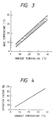
- the radiating fin plate 10 and the radiating fins 11 are exposed to the outside air so that it is maintained close to an ambient temperature.
- the base plate temperature measured by the base temperature sensor 1 may be, as shown in Fig. 3, considered to be substantially equal to the ambient temperature.
- the rotor temperature control system forms a heat-exchanging flow path extending from the rotor 6 through the bowl 7, the spacers 8, the thermoelectric cooling/heating elements 9, and the radiating fins 12 to the ambient air, and vice versa.
- the temperature of an intermediate part of the system such as the bowl 7 may be determined based on a constant rate, dependent upon mechanical arrangements of the system, relative to the rotor temperature and the ambient temperature.
- the amount of heat absorption, or heat exchange of the thermoelectric cooling/heating element 9 i.e., the operation factor of the temperature regulating assembly 17) is uniformly determined based on the rotor temperature and the ambient temperature.
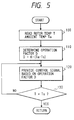
- the operation factor D required for regulating the rotor temperature to a target rotor temperature Ts is, as shown in Fig. 4, determined within a range of 0% to 100% based on an ambient temperature Ta according to the following equation.
- D K ⁇ (Ta - Ts) where K is a coefficient, peculiar to the system, as described above, dependent upon the mechanical arrangements of the system.
- the operation factor D may alternatively be determined by look-up using mapped data to select an appropriate one from among a plurality of values prestored in a memory based on the ambient temperature every initiation of operation of the system.
- FIG. 5 a flowchart of a program or sequence of the logical steps performed by the CPU 20.
- step 100 After entering the program in response to a starting operation of the system, the routine proceeds to step 100 wherein the rotor temperature T and the ambient temperature Ta are determined based on sensor signals from the base temperature sensor 1 and the radiating temperature sensor 2.
- step 120 a control signal having a current value corresponding to the operation factor D determined in step 110 is provided to the thermoelectric cooling/heating elements 9, respectively.
- step 130 it is determined whether the rotor temperature T reaches the target rotor temperature Ts or not. If a NO answer is obtained concluding that the rotor temperature T does not yet reach the target rotor temperature Ts, the routine returns back to step 120. Alternatively, if a YES answer is obtained in step 130, the routine returns back to the initial step.
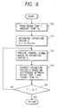
- Figs. 6 shows a flowchart representing an alternate embodiment according to the invention. This embodiment is different from the one, as shown in Fig. 5, only in that step 140 is provided after step 120, and explanation of other steps will be omitted here.
- step 140 the operation factor D is corrected, under the PID control, as discussed in the introductory part of the specification, by adding a correction operation factor which is determined based on an integration value derived by adding an error in time-sequence which will develop between the rotor temperature T and the target rotor temperature Ts and a variation in the rotor temperature T.
Landscapes
- Physics & Mathematics (AREA)
- General Physics & Mathematics (AREA)
- Engineering & Computer Science (AREA)
- Automation & Control Theory (AREA)
- Centrifugal Separators (AREA)
Description
Claims (5)
- A rotor temperature control system for a centrifuge comprising:ambient temperature determining means (1) for determining ambient temperature around the system to provide a signal indicative thereof;temperature regulating means (17) for regulating temperature of a rotor (6) of the centrifuge according to an operation factor variable within a range of preselected maximum to minimum values; andcontrolling means (20), responsive to the signal from said ambient temperature determining means (1), for controlling the operation factor of said temperature regulating means (17) in a preselected relation to the ambient temperature and a given target rotor temperature to modify the temperature of the rotor (6) to the target rotor temperature;
characterized in thatsaid rotor temperature control system further comprises rotor temperature determining means (22) for determining temperature of the rotor (6) and providing a signal indicative thereof, and in that said controlling (20) is provided for correcting the operation factor of said temperature regulating means (17) determined in the pre-selected relation to the ambient temperature and the given target rotor temperature according to a correction value which is based on a difference between the rotor temperature determined by said rotor temperature determining means (2) and the target rotor temperature. - The rotor temperature control system as set forth in claim 1,
characterized in thatsaid temperature regulating means (17) includes heat radiating/absorbing means (9) surrounding the rotor (6) and heat-exchanging means (10, 11) operable to transfer heat between ambient air and the heat radiating/absorbing means (9), said ambient temperature determining means (1) monitoring temperature of the heat-exchanging means (10, 11) determine the ambient temperature. - The rotor temperature control system as set forth in claim 1,
characterized in thatthe rotor temperature determining means (2) includes a radiating temperature sensor which detects radiation heat produced from the rotor (6), said controlling means (20) determining the rotor temperature based on the radiation heat from the rotor (6) and the ambient temperature determined by said ambient temperature determining means (1). - A rotor temperature controlling method for controlling temperature of a rotor (6) of a centrifuge comprising the steps of:determining ambient temperature around temperature regulating means (17) for regulating temperature of the rotor (6) according to an operation factor variable within a range of preselected maximum to minimum values; determining a value of the operation factor of said temperature regulating means (17) in a preselected relation to the ambient temperature and a given target rotor temperature; andproviding a control signal to said temperature regulating means (17) to operate said temperature regulating means (17) at the operation factor determined in said operation factor determining step for modifying the temperature of the rotor (6) to the target rotor temperature;
characterized in thatsaid rotor temperature controlling method further comprises the steps of determining temperature of the rotor (6) and correcting the operation factor of said temperature regulating means (17) determined in the preselected relation to the ambient temperature and the given target rotor temperature according to a correction value which is based on a difference between the rotor temperature determined by rotor temperature determining means (2) and the target rotor temperature. - The rotor temperature controlling method as set forth in claim 4,
characterized in thatsaid temperature regulating means (17) includes heat radiating/adsorbing means (9) surrounding the rotor (6) and heat-exchanging means (10, 11) operable to transfer heat between ambient air and the heat radiating/adsorbing means (9), and in that said ambient temperature determining step includes monitoring temperature of the heat-exchanging means (10, 11) to determine the ambient temperature.
Applications Claiming Priority (2)
| Application Number | Priority Date | Filing Date | Title |
|---|---|---|---|
| JP338650/92 | 1992-12-18 | ||
| JP33865092A JP3284628B2 (en) | 1992-12-18 | 1992-12-18 | centrifuge |
Publications (2)
| Publication Number | Publication Date |
|---|---|
| EP0602639A1 EP0602639A1 (en) | 1994-06-22 |
| EP0602639B1 true EP0602639B1 (en) | 1998-04-08 |
Family
ID=18320174
Family Applications (1)
| Application Number | Title | Priority Date | Filing Date |
|---|---|---|---|
| EP93120317A Expired - Lifetime EP0602639B1 (en) | 1992-12-18 | 1993-12-16 | Rotor temperature control system |
Country Status (4)
| Country | Link |
|---|---|
| US (1) | US5619422A (en) |
| EP (1) | EP0602639B1 (en) |
| JP (1) | JP3284628B2 (en) |
| DE (1) | DE69317865T2 (en) |
Families Citing this family (8)
| Publication number | Priority date | Publication date | Assignee | Title |
|---|---|---|---|---|
| JP2004064945A (en) * | 2002-07-31 | 2004-02-26 | Hitachi Koki Co Ltd | Rotating body drive |
| US8150558B2 (en) * | 2004-12-08 | 2012-04-03 | Iwate University | Temperature control method and temperature controller |
| DE202007004983U1 (en) * | 2007-04-04 | 2007-06-14 | Schaeffler Kg | Drive cooling device, e.g. for centrifuge via ambient air, has exhaust wheel which has air shaft for admission of exhaust wheel and which is mechanically decoupled by drive shaft of centrifuge drive |
| US8200347B2 (en) * | 2009-01-22 | 2012-06-12 | Mitsubishi Electric Research Laboratories, Inc. | Method and apparatus for hybrid resetting states proportional-integral-derivative and lag controllers |
| JP5861988B2 (en) * | 2011-04-15 | 2016-02-16 | 日立工機株式会社 | centrifuge |
| DE102014107294B4 (en) * | 2014-05-23 | 2017-02-09 | Andreas Hettich Gmbh & Co. Kg | centrifuge |
| CN105652916B (en) * | 2016-01-06 | 2017-12-01 | 京东方科技集团股份有限公司 | Temperature of processor control circuit |
| US11965874B2 (en) * | 2019-12-06 | 2024-04-23 | Ganapathi Pamula | Sample processing unit (SPU)-equipped drone for transporting and processing biological materials and method of using same |
Family Cites Families (11)
| Publication number | Priority date | Publication date | Assignee | Title |
|---|---|---|---|---|
| DE3113608A1 (en) * | 1980-04-03 | 1982-04-01 | Appliance Control Systems Pty. Ltd., Melbourne, Victoria | Regulation device |
| DE3343516C2 (en) * | 1983-12-01 | 1985-10-31 | Berthold Hermle Kg, 7209 Gosheim | Refrigerated centrifuge with interchangeable rotors |
| GB2162972B (en) * | 1984-08-10 | 1987-09-30 | Kelvin Lab Limited | Control of system parameters |
| DE3632671A1 (en) * | 1985-11-13 | 1987-05-21 | Heidelberger Druckmasch Ag | DEVICE FOR TEMPERATURE MONITORING OF A DC CURRENT SHUTTER MOTOR FOR DRIVING ROTARY PRINTING MACHINES |
| DD243650A1 (en) * | 1985-12-02 | 1987-03-11 | Medizin Labortechnik Veb K | METHOD FOR TEMPERATING THE ROTORS OF ULTRA CENTRIFUGES |
| DD266745A1 (en) * | 1986-01-29 | 1989-04-12 | Medizin Labortechnik Veb K | METHOD FOR TEMPERATING THE ROTORS OF ULTRA CENTRIFUGES |
| US4785637A (en) * | 1987-05-22 | 1988-11-22 | Beckman Instruments, Inc. | Thermoelectric cooling design |
| US4845341A (en) * | 1988-04-12 | 1989-07-04 | Robertshaw Controls Company | Heating system, control device therefor and methods of making the same |
| US4939437A (en) * | 1988-06-22 | 1990-07-03 | Siemens Energy & Automation, Inc. | Motor controller |
| US5002226A (en) * | 1990-01-16 | 1991-03-26 | Honeywell, Inc. | Thermostat with mechanical heat anticipation and droop control |
| US5397515A (en) * | 1992-10-30 | 1995-03-14 | Allen-Bradley Company, Inc. | Injection molding machine temperature control system |
-
1992
- 1992-12-18 JP JP33865092A patent/JP3284628B2/en not_active Expired - Lifetime
-
1993
- 1993-12-16 EP EP93120317A patent/EP0602639B1/en not_active Expired - Lifetime
- 1993-12-16 DE DE69317865T patent/DE69317865T2/en not_active Expired - Lifetime
- 1993-12-17 US US08/168,311 patent/US5619422A/en not_active Expired - Lifetime
Also Published As
| Publication number | Publication date |
|---|---|
| DE69317865D1 (en) | 1998-05-14 |
| JP3284628B2 (en) | 2002-05-20 |
| EP0602639A1 (en) | 1994-06-22 |
| DE69317865T2 (en) | 1998-08-06 |
| US5619422A (en) | 1997-04-08 |
| JPH06182259A (en) | 1994-07-05 |
Similar Documents
| Publication | Publication Date | Title |
|---|---|---|
| CA1244112A (en) | Means for setting the switching on and off periods of a burner of a hot water heating installation | |
| US7320434B2 (en) | Method of controlling electronic controlled thermostat | |
| KR100348588B1 (en) | Cooling system for vehicles | |
| EP2333268B1 (en) | Cooling system for engine | |
| JPH0259289B2 (en) | ||
| EP0206165A1 (en) | Clock thermostat | |
| US5619422A (en) | Rotor temperature control system | |
| US7171927B2 (en) | Control method for electronically controlled thermostat | |
| US9091471B2 (en) | Air conditioning apparatus with temperature responsive correction of upper limit rotational speed for a compressor | |
| JPH11287123A (en) | Cooling control device for internal combustion engine | |
| JP2573870B2 (en) | Cooling water flow control device for internal combustion engine | |
| US20190085752A1 (en) | Method and system for coolant flow control for a prime mover in a vehicle propulsion system | |
| JP2982322B2 (en) | Automatic temperature control device for absorption refrigerator | |
| JPH0473473A (en) | Coolant control device for internal combustion engine | |
| KR20100088426A (en) | Control method of air conditioner for vehicle | |
| JPH038457B2 (en) | ||
| JP2554452Y2 (en) | Temperature controller | |
| US4771739A (en) | Cooling system for an internal combustion engine | |
| JP2003184555A (en) | Dynamometer system for engine testing | |
| JP4123826B2 (en) | Water temperature control device | |
| JPH028629A (en) | Separate type heating device | |
| JPS6326825B2 (en) | ||
| JP2676197B2 (en) | Temperature control device for co-generation system | |
| JPH0214967B2 (en) | ||
| JPH0545011A (en) | Vending machine cooling system |
Legal Events
| Date | Code | Title | Description |
|---|---|---|---|
| PUAI | Public reference made under article 153(3) epc to a published international application that has entered the european phase |
Free format text: ORIGINAL CODE: 0009012 |
|
| AK | Designated contracting states |
Kind code of ref document: A1 Designated state(s): DE FR IT |
|
| 17P | Request for examination filed |
Effective date: 19941117 |
|
| 17Q | First examination report despatched |
Effective date: 19960229 |
|
| GRAG | Despatch of communication of intention to grant |
Free format text: ORIGINAL CODE: EPIDOS AGRA |
|
| GRAG | Despatch of communication of intention to grant |
Free format text: ORIGINAL CODE: EPIDOS AGRA |
|
| GRAH | Despatch of communication of intention to grant a patent |
Free format text: ORIGINAL CODE: EPIDOS IGRA |
|
| GRAH | Despatch of communication of intention to grant a patent |
Free format text: ORIGINAL CODE: EPIDOS IGRA |
|
| GRAA | (expected) grant |
Free format text: ORIGINAL CODE: 0009210 |
|
| AK | Designated contracting states |
Kind code of ref document: B1 Designated state(s): DE FR IT |
|
| ET | Fr: translation filed | ||
| REF | Corresponds to: |
Ref document number: 69317865 Country of ref document: DE Date of ref document: 19980514 |
|
| ITF | It: translation for a ep patent filed | ||
| PLBE | No opposition filed within time limit |
Free format text: ORIGINAL CODE: 0009261 |
|
| STAA | Information on the status of an ep patent application or granted ep patent |
Free format text: STATUS: NO OPPOSITION FILED WITHIN TIME LIMIT |
|
| 26N | No opposition filed | ||
| PGFP | Annual fee paid to national office [announced via postgrant information from national office to epo] |
Ref country code: DE Payment date: 20121213 Year of fee payment: 20 |
|
| PGFP | Annual fee paid to national office [announced via postgrant information from national office to epo] |
Ref country code: IT Payment date: 20121214 Year of fee payment: 20 |
|
| PGFP | Annual fee paid to national office [announced via postgrant information from national office to epo] |
Ref country code: FR Payment date: 20130107 Year of fee payment: 20 |
|
| REG | Reference to a national code |
Ref country code: DE Ref legal event code: R071 Ref document number: 69317865 Country of ref document: DE |
|
| REG | Reference to a national code |
Ref country code: DE Ref legal event code: R071 Ref document number: 69317865 Country of ref document: DE |
|
| PG25 | Lapsed in a contracting state [announced via postgrant information from national office to epo] |
Ref country code: DE Free format text: LAPSE BECAUSE OF EXPIRATION OF PROTECTION Effective date: 20131217 |