EP0602467A1 - Mit seltenen Erden dotierte faseroptische Verstärker - Google Patents
Mit seltenen Erden dotierte faseroptische Verstärker Download PDFInfo
- Publication number
- EP0602467A1 EP0602467A1 EP93119433A EP93119433A EP0602467A1 EP 0602467 A1 EP0602467 A1 EP 0602467A1 EP 93119433 A EP93119433 A EP 93119433A EP 93119433 A EP93119433 A EP 93119433A EP 0602467 A1 EP0602467 A1 EP 0602467A1
- Authority
- EP
- European Patent Office
- Prior art keywords
- thermal expansion
- core
- amplifier
- layer
- cladding
- Prior art date
- Legal status (The legal status is an assumption and is not a legal conclusion. Google has not performed a legal analysis and makes no representation as to the accuracy of the status listed.)
- Granted
Links
Images


Classifications
-
- G—PHYSICS
- G02—OPTICS
- G02B—OPTICAL ELEMENTS, SYSTEMS OR APPARATUS
- G02B6/00—Light guides; Structural details of arrangements comprising light guides and other optical elements, e.g. couplings
- G02B6/02—Optical fibres with cladding with or without a coating
- G02B6/036—Optical fibres with cladding with or without a coating core or cladding comprising multiple layers
- G02B6/03616—Optical fibres characterised both by the number of different refractive index layers around the central core segment, i.e. around the innermost high index core layer, and their relative refractive index difference
- G02B6/03638—Optical fibres characterised both by the number of different refractive index layers around the central core segment, i.e. around the innermost high index core layer, and their relative refractive index difference having 3 layers only
- G02B6/0365—Optical fibres characterised both by the number of different refractive index layers around the central core segment, i.e. around the innermost high index core layer, and their relative refractive index difference having 3 layers only arranged - - +
-
- C—CHEMISTRY; METALLURGY
- C03—GLASS; MINERAL OR SLAG WOOL
- C03B—MANUFACTURE, SHAPING, OR SUPPLEMENTARY PROCESSES
- C03B37/00—Manufacture or treatment of flakes, fibres, or filaments from softened glass, minerals, or slags
- C03B37/01—Manufacture of glass fibres or filaments
- C03B37/012—Manufacture of preforms for drawing fibres or filaments
- C03B37/014—Manufacture of preforms for drawing fibres or filaments made entirely or partially by chemical means, e.g. vapour phase deposition of bulk porous glass either by outside vapour deposition [OVD], or by outside vapour phase oxidation [OVPO] or by vapour axial deposition [VAD]
- C03B37/018—Manufacture of preforms for drawing fibres or filaments made entirely or partially by chemical means, e.g. vapour phase deposition of bulk porous glass either by outside vapour deposition [OVD], or by outside vapour phase oxidation [OVPO] or by vapour axial deposition [VAD] by glass deposition on a glass substrate, e.g. by inside-, modified-, plasma-, or plasma modified- chemical vapour deposition [ICVD, MCVD, PCVD, PMCVD], i.e. by thin layer coating on the inside or outside of a glass tube or on a glass rod
- C03B37/01807—Reactant delivery systems, e.g. reactant deposition burners
- C03B37/01838—Reactant delivery systems, e.g. reactant deposition burners for delivering and depositing additional reactants as liquids or solutions, e.g. for solution doping of the deposited glass
-
- C—CHEMISTRY; METALLURGY
- C03—GLASS; MINERAL OR SLAG WOOL
- C03C—CHEMICAL COMPOSITION OF GLASSES, GLAZES OR VITREOUS ENAMELS; SURFACE TREATMENT OF GLASS; SURFACE TREATMENT OF FIBRES OR FILAMENTS MADE FROM GLASS, MINERALS OR SLAGS; JOINING GLASS TO GLASS OR OTHER MATERIALS
- C03C13/00—Fibre or filament compositions
- C03C13/04—Fibre optics, e.g. core and clad fibre compositions
- C03C13/045—Silica-containing oxide glass compositions
- C03C13/046—Multicomponent glass compositions
-
- G—PHYSICS
- G02—OPTICS
- G02B—OPTICAL ELEMENTS, SYSTEMS OR APPARATUS
- G02B6/00—Light guides; Structural details of arrangements comprising light guides and other optical elements, e.g. couplings
- G02B6/02—Optical fibres with cladding with or without a coating
- G02B6/036—Optical fibres with cladding with or without a coating core or cladding comprising multiple layers
- G02B6/03616—Optical fibres characterised both by the number of different refractive index layers around the central core segment, i.e. around the innermost high index core layer, and their relative refractive index difference
- G02B6/03638—Optical fibres characterised both by the number of different refractive index layers around the central core segment, i.e. around the innermost high index core layer, and their relative refractive index difference having 3 layers only
- G02B6/03644—Optical fibres characterised both by the number of different refractive index layers around the central core segment, i.e. around the innermost high index core layer, and their relative refractive index difference having 3 layers only arranged - + -
-
- H—ELECTRICITY
- H01—ELECTRIC ELEMENTS
- H01S—DEVICES USING THE PROCESS OF LIGHT AMPLIFICATION BY STIMULATED EMISSION OF RADIATION [LASER] TO AMPLIFY OR GENERATE LIGHT; DEVICES USING STIMULATED EMISSION OF ELECTROMAGNETIC RADIATION IN WAVE RANGES OTHER THAN OPTICAL
- H01S3/00—Lasers, i.e. devices using stimulated emission of electromagnetic radiation in the infrared, visible or ultraviolet wave range
- H01S3/05—Construction or shape of optical resonators; Accommodation of active medium therein; Shape of active medium
- H01S3/06—Construction or shape of active medium
- H01S3/063—Waveguide lasers, i.e. whereby the dimensions of the waveguide are of the order of the light wavelength
- H01S3/067—Fibre lasers
- H01S3/06708—Constructional details of the fibre, e.g. compositions, cross-section, shape or tapering
-
- C—CHEMISTRY; METALLURGY
- C03—GLASS; MINERAL OR SLAG WOOL
- C03B—MANUFACTURE, SHAPING, OR SUPPLEMENTARY PROCESSES
- C03B2201/00—Type of glass produced
- C03B2201/06—Doped silica-based glasses
- C03B2201/08—Doped silica-based glasses doped with boron or fluorine or other refractive index decreasing dopant
- C03B2201/10—Doped silica-based glasses doped with boron or fluorine or other refractive index decreasing dopant doped with boron
-
- C—CHEMISTRY; METALLURGY
- C03—GLASS; MINERAL OR SLAG WOOL
- C03B—MANUFACTURE, SHAPING, OR SUPPLEMENTARY PROCESSES
- C03B2201/00—Type of glass produced
- C03B2201/06—Doped silica-based glasses
- C03B2201/08—Doped silica-based glasses doped with boron or fluorine or other refractive index decreasing dopant
- C03B2201/12—Doped silica-based glasses doped with boron or fluorine or other refractive index decreasing dopant doped with fluorine
-
- C—CHEMISTRY; METALLURGY
- C03—GLASS; MINERAL OR SLAG WOOL
- C03B—MANUFACTURE, SHAPING, OR SUPPLEMENTARY PROCESSES
- C03B2201/00—Type of glass produced
- C03B2201/06—Doped silica-based glasses
- C03B2201/08—Doped silica-based glasses doped with boron or fluorine or other refractive index decreasing dopant
- C03B2201/14—Doped silica-based glasses doped with boron or fluorine or other refractive index decreasing dopant doped with boron and fluorine
-
- C—CHEMISTRY; METALLURGY
- C03—GLASS; MINERAL OR SLAG WOOL
- C03B—MANUFACTURE, SHAPING, OR SUPPLEMENTARY PROCESSES
- C03B2201/00—Type of glass produced
- C03B2201/06—Doped silica-based glasses
- C03B2201/20—Doped silica-based glasses doped with non-metals other than boron or fluorine
- C03B2201/28—Doped silica-based glasses doped with non-metals other than boron or fluorine doped with phosphorus
-
- C—CHEMISTRY; METALLURGY
- C03—GLASS; MINERAL OR SLAG WOOL
- C03B—MANUFACTURE, SHAPING, OR SUPPLEMENTARY PROCESSES
- C03B2201/00—Type of glass produced
- C03B2201/06—Doped silica-based glasses
- C03B2201/30—Doped silica-based glasses doped with metals, e.g. Ga, Sn, Sb, Pb or Bi
- C03B2201/31—Doped silica-based glasses doped with metals, e.g. Ga, Sn, Sb, Pb or Bi doped with germanium
-
- C—CHEMISTRY; METALLURGY
- C03—GLASS; MINERAL OR SLAG WOOL
- C03B—MANUFACTURE, SHAPING, OR SUPPLEMENTARY PROCESSES
- C03B2201/00—Type of glass produced
- C03B2201/06—Doped silica-based glasses
- C03B2201/30—Doped silica-based glasses doped with metals, e.g. Ga, Sn, Sb, Pb or Bi
- C03B2201/34—Doped silica-based glasses doped with metals, e.g. Ga, Sn, Sb, Pb or Bi doped with rare earth metals, i.e. with Sc, Y or lanthanides, e.g. for laser-amplifiers
- C03B2201/36—Doped silica-based glasses doped with metals, e.g. Ga, Sn, Sb, Pb or Bi doped with rare earth metals, i.e. with Sc, Y or lanthanides, e.g. for laser-amplifiers doped with rare earth metals and aluminium, e.g. Er-Al co-doped
-
- C—CHEMISTRY; METALLURGY
- C03—GLASS; MINERAL OR SLAG WOOL
- C03B—MANUFACTURE, SHAPING, OR SUPPLEMENTARY PROCESSES
- C03B2203/00—Fibre product details, e.g. structure, shape
- C03B2203/10—Internal structure or shape details
- C03B2203/22—Radial profile of refractive index, composition or softening point
-
- H—ELECTRICITY
- H01—ELECTRIC ELEMENTS
- H01S—DEVICES USING THE PROCESS OF LIGHT AMPLIFICATION BY STIMULATED EMISSION OF RADIATION [LASER] TO AMPLIFY OR GENERATE LIGHT; DEVICES USING STIMULATED EMISSION OF ELECTROMAGNETIC RADIATION IN WAVE RANGES OTHER THAN OPTICAL
- H01S3/00—Lasers, i.e. devices using stimulated emission of electromagnetic radiation in the infrared, visible or ultraviolet wave range
- H01S3/05—Construction or shape of optical resonators; Accommodation of active medium therein; Shape of active medium
- H01S3/06—Construction or shape of active medium
- H01S3/063—Waveguide lasers, i.e. whereby the dimensions of the waveguide are of the order of the light wavelength
- H01S3/067—Fibre lasers
- H01S3/06708—Constructional details of the fibre, e.g. compositions, cross-section, shape or tapering
- H01S3/06729—Peculiar transverse fibre profile
-
- H—ELECTRICITY
- H01—ELECTRIC ELEMENTS
- H01S—DEVICES USING THE PROCESS OF LIGHT AMPLIFICATION BY STIMULATED EMISSION OF RADIATION [LASER] TO AMPLIFY OR GENERATE LIGHT; DEVICES USING STIMULATED EMISSION OF ELECTROMAGNETIC RADIATION IN WAVE RANGES OTHER THAN OPTICAL
- H01S3/00—Lasers, i.e. devices using stimulated emission of electromagnetic radiation in the infrared, visible or ultraviolet wave range
- H01S3/09—Processes or apparatus for excitation, e.g. pumping
- H01S3/091—Processes or apparatus for excitation, e.g. pumping using optical pumping
- H01S3/094—Processes or apparatus for excitation, e.g. pumping using optical pumping by coherent light
- H01S3/094003—Processes or apparatus for excitation, e.g. pumping using optical pumping by coherent light the pumped medium being a fibre
- H01S3/094011—Processes or apparatus for excitation, e.g. pumping using optical pumping by coherent light the pumped medium being a fibre with bidirectional pumping, i.e. with injection of the pump light from both two ends of the fibre
-
- H—ELECTRICITY
- H01—ELECTRIC ELEMENTS
- H01S—DEVICES USING THE PROCESS OF LIGHT AMPLIFICATION BY STIMULATED EMISSION OF RADIATION [LASER] TO AMPLIFY OR GENERATE LIGHT; DEVICES USING STIMULATED EMISSION OF ELECTROMAGNETIC RADIATION IN WAVE RANGES OTHER THAN OPTICAL
- H01S3/00—Lasers, i.e. devices using stimulated emission of electromagnetic radiation in the infrared, visible or ultraviolet wave range
- H01S3/14—Lasers, i.e. devices using stimulated emission of electromagnetic radiation in the infrared, visible or ultraviolet wave range characterised by the material used as the active medium
- H01S3/16—Solid materials
- H01S3/1691—Solid materials characterised by additives / sensitisers / promoters as further dopants
Definitions
- Optical amplifiers are optical devices in which a length of rare earth doped optical fibre is pumped at a pump wavelength of the rare earth dopant, to cause population inversion of the dopant, which causes a signal, at a signal wavelength, propagating along said fibre to be amplified.
- An amplifier has a gain efficiency which is defined as the ratio between the amplification gain of the signal and the corresponding pump power.
- NA (n12 - n22) 1/2
- n1 and n2 being the refractive indexes of core and cladding respectively.
- a refractive index raising dopant such as GeO2 typically used in a SiO2 core of a fibre having a SiO2 cladding
- DE 4041151A discloses a preform for a fibre having a GeO2 doped SiO2 core and P2O5 and F2 doped silica cladding in which the content of the P2O5 in the cladding increases from the outer surface to the inner surface thereof; this is said useful to achieve a drawing speed of 120 m/min and an attenuation of 0.3 dB/km at 1300 nm.
- the difference in thermal expansion coefficients was cause of stress at core-cladding interface and of a stress-related background loss or attenuation, particularly at certain wavelengths, and more particularly at pump wavelength in rare earth doped fibre amplifiers.
- the stess-related fiber attenuation would have been considered negligible particularly in a fiber amplifier, making use of an active fiber of some meters length only, doped with a dopant having considerably higher light attenuating properties at the signal wavelength.
- an amplifier having an erbium doped fibre, without erbium confinement, having a NA higher than 0.2 in which the background loss of the fibre at the pump wavelength is at a level which does not significantly reduce the optimum gain efficiency of the amplifier from its theoretical value.
- this is achieved by having the difference in the coefficients of thermal expansion of the core and cladding adjacent the core/cladding interface at a value which is less than a predetermined value which corresponds to a ratio of erbium loss to background greater than a predetermined ratio.
- the invention provides an optical amplifier for amplifying an optical signal having a signal wavelength, comprising an optical fibre having an erbium doped core surrounded by cladding, a pump for pumping the fibre with pump light at a pump wavelength coupled to the fibre, input means for inputting a signal to be amplified to the amplifier and output means for outputting an amplified signal from the amplifier, wherein said fibre has a NA higher than 0.2 and wherein the difference in the coefficient of thermal expansion of the core adjacent the core/cladding interface and the coefficient of thermal expansion of the cladding at at least one radius less than 2 ⁇ m from said interface is lower than a predetermined value, corresponding to a ratio of erbium loss to background loss, at said pump wavelength, greater than a minimum ratio calculated by a given increasing function of the ratio erbium loss/background loss versus erbium loss, in which said minimum ratio is about 20 when erbium loss is 0.15 dB/m and about 120 when erbium loss is 3.5 dB/m
- the above-mentioned given function may be linearly increasing in the range of erbium loss between 0.15 and 3.5 dB/m.
- the erbium loss in the fibre corresponds to an erbium content lower than a value at which significant erbium clustering in the glass takes place.
- the erbium content may be lower than a value corresponding to an erbium loss of 3.3dB/m or more preferably 2.5 dB/m.
- the difference in the coefficient of thermal expansion of the core adjacent the core/cladding interface and the coefficient of thermal expansion of the cladding at at least one radius less than 2 ⁇ m from said interface may be less than 50%, preferably less than 20% and more preferably less than 10%.
- the cladding may comprise an outer annular layer having a substantially constant coefficient of thermal expansion throughout its thickness and the difference in said substantially constant coefficient of thermal expansion and the coefficient of thermal expansion of the cladding radially inwardly of the outer layer but adjacent the outer layer is less than 50%, preferably less than 20% and more preferably less than 10%.
- the coefficient of thermal expansion of said cladding varies gradually between adjacent said outer layer and said at least one radius in a stress relieving annular layer of said cladding between said outer layer and said core.
- the stress relieving annular layer may contain thermal expansion modifying dopant, such as at least one of P2O5, GeO2 and B2O3, present in an amount which increases from the radially outer region to the radially inner region thereof.
- thermal expansion modifying dopant such as at least one of P2O5, GeO2 and B2O3, present in an amount which increases from the radially outer region to the radially inner region thereof.
- the thermal expansion modifying dopant may also modify the refractive index of the annular stress relieving layer in which case preferably that layer contains a refractive index modifying dopant (such as F2, when the thermal expansion modifying dopant is a refractive index raiser) present in an amount which increases from the radially outer region to the radially inner region thereof to compensate for the refractive index modifying effect of the thermal expansion modifying dopant, whereby the refractive index of the annular stress relieving layer is substantially constant throughout its thickness.
- a refractive index modifying dopant such as F2
- the refractive index of the annular stress relieving layer varies by less than 0.4% across its thickness, and preferably is substantially the same as that of the annular outer layer.
- the cladding may comprise an annular barrier layer immediately adjacent the core for providing a barrier to diffusion of dopants between the core and the remainder of the cladding radially outwardly of the barrier layer.
- the cladding may also be defined as having an outer annular layer having a first coefficient of thermal expansion, the core having a second coefficient of thermal expansion, and the cladding having an annular stress relieving layer between said outer layer and said core having a coefficient of thermal expansion which varies radially inwardly from a third value to a fourth value, the third value being closer to the first value than the second value and the fourth value being closer to the second value than the first value.
- first and third values are substantially the same and the second and fourth values are substantially the same, and an annular barrier layer may be provided between said core and said stress relieving layer for providing a barrier to diffusion of dopants between said core and stress relieving layer.
- the barrier layer which will have a coefficient of thermal expansion significantly different from that of the adjacent core or cladding, should have a small radial thickness such that residual stress therein is small.
- the barrier layer may have a radial thickness between 0.5 and 1.5 ⁇ m.
- the maximum radial thickness may be less than or equal to 0.22 ( ⁇ c .r c )/ ⁇ b where ⁇ c the coefficient of thermal expansion of the core, ⁇ b is the coefficient of thermal expansion of the barrier layer, and r c is the radius of the core.
- the invention also includes a telecommunication system comprising a signal source for generating signals at a signal wavelength, a signal receiver for receiving signals at said signal wavelength, and a signal transmission fibre line between said source and receiver line for transmitting said signals, said line including an optical amplifier therein as defined above.
- the invention includes an optical fibre having a NA higher than 0.2, comprising a rare earth doped core and cladding surrounding said core, wherein the difference in the coefficient of thermal expansion of the core adjacent the core/cladding interface and the coefficient of thermal expansion of the cladding at at least one radius less than 2 ⁇ m from said interface is less than 50%.
- the invention includes an optical fibre comprising a core surrounded with a cladding, an outer annular layer of the cladding having a first coefficient of thermal expansion, the core having a second coefficient of thermal expansion, and the cladding having an annular stress relieving layer between said outer layer and said core having a coefficient of thermal expansion which varies radially inwardly from a third value to a fourth value, the third value being closer to the first value than the second value and the fourth value being closer to the second value than the first value.
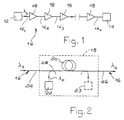
- a telecommunication system 10 comprising a signal source 12 for generating signals at a signal wavelength ⁇ s , a signal receiver 14 for receiving signals at the signal wavelength ⁇ s , and a signal transmission fibre line 16 between the source and receiver for transmitting the signals.
- the line includes a plurality of optical amplifiers 18 therein for amplifying the signal from an upstream length of line 16 which signal has been attenuated during transmission therealong for onward transmission along a downstream length of line 16.
- the system 10 may be a submarine telecommunication system, in which the line 16 comprises optical cables 161, 162, 163 ... 16 n respectively connecting the source 12 to the first of the amplifiers 18, that amplifier to the adjacent one and the last amplifier to the receiver 14.
- the line 16 comprises optical cables 161, 162, 163 ... 16 n respectively connecting the source 12 to the first of the amplifiers 18, that amplifier to the adjacent one and the last amplifier to the receiver 14.
- Each optical cable 161, 162 ... 16 n comprises at least one optical fibre and has a length which may be of some tens of kilometres to some hundreds of kilometres.
- Each optical amplifier 18 can amplify the signal with a gain which is of the order of about 20-30 dB, or greater.
- each optical amplifier 18 comprises a length of erbium doped optical fibre 20, a pump laser 22 for pumping the fibre 20 at a pump wavelength coupled to an end thereof and means coupling each end of the fibre 20 to a respective transmission fibre 24, 26 of the line 16 upstream and downstream of the amplifier for inputting a signal to be amplified to the amplifier and outputting an amplified signal from the amplifier.
- the pump 22 and fibre 24 upstream of the amplifier are coupled via a dichroic coupler 28 to an upstream end of the erbium doped fibre 20 so that the pump and signal light co-propagate through the fibre 20.
- the pump laser may instead be coupled to the downstream end of the erbium doped fibre 20 as indicated in dotted line at 23 so that the pump and signal light counterpropagate through the fibre or a respective pump laser may be coupled to each end of the fibre 20.
- the wavelength of the pump is 980 nm.
- An erbium doped fiber suitable for use with these amplifiers, is a single mode fiber, both at signal and pump wavelength, made of SiO2 glass, having the core doped with GeO2, or Al2O3, or both, defining an area with higher refractive index; a cladding surrounds the core, having a constant refractive index, lower than that of the core, defining a so called "step index" profile of the fiber.
- the cladding is formed by an inner, or synthetic cladding, and by an outer cladding, made of pure silica, having the same refractive indexes.
- This fiber structure and particularly the cladding composition, conveniently enable direct and low-loss fiber-to-fiber fusion splicing with the conventional transmission optical fibers.
- the erbium doped fiber is made through the so called “MCVD” tecnique, well known in the art, which produces a particularly sharp step-index profile, with an index change, at the core-cladding interface, confined in less than about 0.5 ⁇ m.
- the MCVD technique is used to make the core and the synthetic cladding of the fiber, that is the area where the light propagates; the addition of dopants such as erbium or alumina is conveniently made by the "solution doping" technique, known in the art.
- the core of the fibre 20 is SiO2 doped with GeO2 (and possibly Al2O3) as an index raiser in addition to erbium.
- the signal has a wavelength in the range 1531- 1536 nm, and the Er doped fibre is doped with GeO2 only to increase the refractive index, taking advantage of the high gain peak of erbium in a SiO2/GeO2 system in that wavelength range.
- the optimum gain efficiency was found to be significantly lower than the theoretical value.
- the NA of the fibres used in the tests would result in the coefficient of thermal expansion of the core being substantially greater than that of the cladding if the cladding were undoped SiO2. For example, for a NA of 0.3 these coefficients would be 3.1 x 10 ⁇ 6C ⁇ 1 for the core and 0.5 x 10 ⁇ 6C ⁇ 1 for the cladding in view of the GeO2 content (approximately 24 mol%) of the core required to provide a NA of 0.3.
- the cladding in the embodiment includes a stress relieving annular layer 30 between an outer SiO2 layer 32 of the cladding and the erbium doped GeO2-SiO2 core which is referenced 34.
- the coefficient of thermal expansion varies radially inwardly from the value of the coefficient of thermal expansion of the outer layer 32 and the value of the coefficient of thermal expansion of the core as indicated by the chain dotted line 36 in Figure 4 which shows the difference ⁇ in this coefficient from that of the outer cladding layer across the fibre for the case where the NA is 0.3.
- the value of the coefficient of thermal expansion of the outer layer is substantially constant throughout its thickness and the value of the coefficient of thermal expansion of the core is substantially constant throughout its thickness.
- the variation in the coefficient of thermal expansion across the thickness of the stress relieving layer 30 is achieved by doping that layer with P2O5, which is a thermal expansion raising dopant, such that the layer 30 contains P2O5 in an amount which increases from the radially outer region of the layer 30 to the radially inner region thereof.
- P2O5 acts as a refractive index raiser.
- the layer 30 is doped with F2, which is a refractive index lowering dopant, such that the layer 30 contains F2 in an amount which increases from the radially outer region of the layer 30 to the radially inner region thereof with a consequent effect on the refractive index, as indicated by the dotted lines 40 in Figure 4, whereby the refractive index of the layer 30 is substantially constant throughout its thickness and is matched to the refractive index of the outer cladding layer 32 as indicated in Figure 4 where the solid line shows the difference ⁇ n in refractive index from that of the outer cladding layer across the fibre.
- the refractive index of the layer 30 is matched to that of the outer layer 32 to preserve the step-index profile of the fibre.
- the content of the P2O5 in the stress relieving layer increases from about 0 mol% at its radially outer region to about 15 mol% at its radially inner region.
- the inclusion of 15 mol% P2O5 gives rise to an increase of about 0.01 in refractive index and about 3 mol% F2 is required to provide a corresponding decrease in refractive index.
- the content of F2 in the stress relieving layer increases from about 0 mol% at its radially outer region to about 3 mol% at its radially inner region.
- Manufacturing tolerances may allow the content of P2O5 and F2 to vary by up to say 0.4 mol% at any given radius from the theoretical content, with a possible resulting variation in the refractive index of the layer 30 across its thickness. However, preferably this variation is less than 0.4%.
- the cladding of the fibre also includes an annular barrier layer 42 immediately adjacent the core 34 for providing a barrier to diffusion of dopants between the core and the remainder of the cladding radially inwardly of the barrier layer 42.
- the barrier layer is provided since diffusion of P2O5 from the stress relieving layer 30 to the core is undesirable.
- the barrier layer is undoped SiO2 and accordingly does not alter the step-index profile of the fibre.
- the coefficient of thermal expansion of the barrier layer is significantly different from that of the core and the radially inner region of the stress relieving layer 30.
- the radial thickness of the barrier layer is sufficiently small that the residual stress therein caused by this difference is small and has minimal effect on the cladding/core interface.
- the fibre illustrated by Figures 3 and 4 is drawn from a preform manufactured using the MCVD process and solution doping.
- Flow rates (in SCC/MIN) and the number of passes of the reagents for forming the preform layers in a SiO2 substrate tube corresponding to the stress relieving layer, barrier layer and core are given in the following table: Passes SiCl4 GeCl4 POCl3 CF2Cl2 O2 Stress relieving layer 30 600 - 0-370 0-7 800 Barrier layer 2 400 - - - 600 Core 1 100 300 - - 300
- Erbium is introduced into the core layer of the preform, without confinement, by solution doping.
- the core 34 has a diameter of 2.3 ⁇ m
- the barrier layer 42 has a radial thickness of 1 ⁇ m (giving it an outside diameter of 4.3 ⁇ m)
- the stress relieving layer 30 has a radial thickness of 5.35 ⁇ m (giving it an outside diameter of 15 ⁇ m)
- the outer cladding layer 32 has a radial thickness of about 55 ⁇ m.
- the fibre has a NA of 0.3 as mentioned previously, a cut-off wavelength of 900 nm, a mode field diameter at 980 nm of 2.6 ⁇ m and a mode field diameter at 1536 nm of 4.2 ⁇ m.
- both of these mode field diameters are within the SiO2 barrier layer 42 and there is no field extension into the stress-relieving layer 30 when the thickness of the barrier layer is 1 ⁇ m. Furthermore, with a thickness of about 5 ⁇ m the change of the coefficient of thermal expansion across the stress relieving layer is about 0.5 x 10 ⁇ 6C ⁇ 1 ⁇ m ⁇ 1 which experimentally has been shown to be preferable for preventing undesirable residual stress and the core/cladding interface.
- the radial thicknesses of the barrier layer and stress relieving layer are 1 ⁇ m and about 5 ⁇ m it is to be understood that the barrier layer may have a radial thickness of between 0.5 and 1.5 ⁇ m and the stress relieving layer may have a radial thickness of between 2.5 and 7.5 ⁇ m.
- the barrier layer will not be thick enough to prevent P2O5 diffusing into the core. Above the upper limit of 1.5 ⁇ m, stress due to the presence of the barrier layer will significantly reduce the effectiveness of the stress relieving layer.
- the ratio of the product of the coefficient of thermal expansion of the barrier layer ⁇ b and its radius r b to the product of the coefficient of thermal expansion of the core ⁇ c and its radius r c should be less than or equal to 0.22.
- the lower limit of 2.5 ⁇ m for the thickness of the stress relieving layer 30 is determined by the need to locate the transition of the coefficient of thermal expansion in the cladding to that of the SiO2 outer layer sufficiently far from the core/cladding interface that there is no adverse effect caused thereby on the optical power of the guided mode.
- the ratio of the outer diameter of the layer 30 to the diameter of the core should be not less than 4.
- the core diameter is 2.3 ⁇ m and the barrier layer outer diameter is 4.3 ⁇ m if the layer 30 had a thickness of 2.5 ⁇ m its outer diameter would be 9.3 ⁇ m which is greater than four times the core diameter.
- the upper limit of 7.5 ⁇ m is determined by the requirement that the presence of the stress relieving layer should not adversely affect the function of the outer layer of the cladding as a support. In this regard it is desirable to satisfy the following condition of radial expansion thermal balance: where R is the outside diameter of the fibre and M is the outside diameter of the stress relieving layer 30.
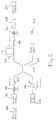
- Figure 5 shows a test apparatus 50 for measuring the gain efficiency of an amplifier using alternative erbium doped fibres.
- the apparatus simulates the amplifier of Figure 2 but has extra components for test purposes.
- the apparatus comprises an erbium doped fibre 52 arranged to be pumped by a pump laser 54 via an optical attenuator 56 and supplied with a signal to be amplified from a function generator 58 and tunable laser 60.
- the pump and signal light co-propagate through the fibre 52 being coupled to one end via a wavelength division multiplexer for coupling wavelengths of 980 nm from the pump laser and 1536 nm from the tunable laser 60 via an optical isolator 64 to the input end of the fibre 52.
- An optical isolator 66 is also provided at the output end of the fibre 52 and a Fabry-Perot optical filter 68 is provided downstream of the isolator 66 so that only the signal of interest is measured by a power meter 70 connected thereto.
- a power meter 72 is connected to the wavelength division multiplexer for measuring the power of the pump light.
- Connectors 74 and 76 are provided upstream and downstream respectively of the isolators 64 and 66 for convenience.
- the theoretical maximum efficiency is calculated considering a number of characteristics of the fibre, including NA, cut-off wavelength ⁇ c , Er confinement factor, fibre length, pump power.
- fibre C is the fibre disclosed in connection with Figures 3 and 4 and fibres A, B, D, I and L are fibres made in the same manner - i.e. fibres in which the cladding is provided with a stress relieving annular layer 30 as described above and may be described as matched index - matched stress (MI-MS).
- Fibres E to H, J, K and N on the other hand have a cladding which is not provided with a stress relieving annular but does have substantially constant refractive index throughout its thickness and accordingly may be described as matched index (MI).
- fibres A to D, I and L provided with a MI-MS cladding produce an optimum gain efficiency close to the theoretical maximum whereas fibres E to H, J and K having NA's of the same order produce optimum gain efficiencies which are significantly lower than the theoretical maximum values.
- the fibres A to D, I and L which produce optimum gain efficiencies close to the theoretical maximum have a relationship between erbium loss and background loss at the pump wavelength which is such that the ratio of erbium loss to background loss is greater than a minimum ratio calculated by a given increasing function of the ratio of erbium loss/background loss versus erbium loss in which the minimum ratio is about 20 when the erbium loss is 0.15 dB/m and about 120 when the erbium loss is about 3.5 dB/m.
- the line is interrupted before erbium loss reaches zero, because a minimum theoretical background loss in the fibre cannot be avoided, and represented with a broken line after an erbium loss greater than about 3, because with increasing erbium content in the fibre (and corresponding erbium loss) the risk of clustering becomes relevant depending on the fibre characteristics and construction, which can alter the results.
- the erbium loss in the fibre should correspond to an erbium content lower than a value at which significant erbium clustering occurs. Having regard to Figure 7, the erbium content should be lower than a value corresponding to an erbium loss of 3.3dB/m or more preferably 2.5dB/m.
- fibre N is not provided with an MI-MS cladding like fibres A to D, I and L, it nevertheless produces an optimum gain efficiency close to the theoretical maximum.
- NA 0.2
- the coefficient of thermal expansion of the stress relieving layer 30 at its radially inner region is not essential to provide an advantageous reduction in the residual stress at the cladding/core interface.
- an advantageous reduction may be provided if the difference is less than say 50%, preferably less than 20% and more preferably less than 10%.
- a 50% difference between the coefficients of thermal expansion of the core and the stress relieving layer at its radially inner region in a fibre having a 0.3 NA has a loss performance which is substantially the same as that of a fibre having a NA of 0.2 in which no stress relieving layer is provided.
- the difference in the thermal expansion of the core and that of the cladding at at least one radius less than 2 ⁇ m from the core cladding interface should be less than 50%, preferably less than 20% and more preferably less than 10%.
- the coefficient of thermal expansion of the stress relieving layer 30 at its radially outer region is same as that of the outer cladding layer 32, in order to reduce residual stress at the interface of these two layers, acceptable results are achievable where the difference between these coefficients is less than 50%, preferably less than 20% and more preferably less than 10%.
- the coefficient of thermal expansion at a given radius is determined by making an analysis of the concentration of the components of the fibre at that radius and referring to known tables.
- the coefficient of thermal expansion of the cladding in the stress relieving layer 30 varies gradually between adjacent the outer layer 30 and the above-mentioned radius less than 2 ⁇ m from the core/cladding interface, and as shown by the chain-dotted line in Figure 4 preferably this variation should be continuous and more preferably substantially uniform.
- the stress relieving layer 30 has a coefficient of thermal expansion which varies radially inwardly from one value, which is closer to the value of the coefficient of thermal expansion of the outer cladding layer 32 than to the value of the coefficient of thermal expansion of the core 34, to another value, which is close to the value of the coefficient of thermal expansion of the core than to the value of the coefficient of thermal expansion of the outer cladding layer.
- these two values of the coefficient of thermal expansion of the layer 30 are substantially the same as the values of the coefficients of thermal expansion of the outer cladding layer and core respectively.
- the barrier layer 42 is described as being of undoped SiO2, some dopant from the core and stress relieving layer will diffuse into it.
- the barrier layer may contain up to 0.1 mol% P2O5, 0.3 mol% F2, 0.4 mol% GeO2, 0.4 mol% Al2O3, 0.1 mol% B2O3, due to diffusion.
- the barrier layer may be intentionally doped with GeO2 (say 1.4 mol%) and F2 (say 0.6 mol%), (in an index-matching relationship), even if this renders less effective the barrier effect and possibly a slightly bigger size of the barrier layer is required.
- the presence of small amounts of dopants in the SiO2 glass of the barrier layer causes the diffusion of the dopants from the core and from the stress relieving layer to increase: accordingly, if dopants are introduced in the barrier layer for any possible reasons, a correspondingly thicker barrier layer would be required to maintain the desired concentration profile in the core and in the stress relieving layer.
- said thickness increase of the barrier layer should not exceed a value causing a significant effect on the background loss.
- dopants may be used in the stress relieving layer.
- a combination of GeO2 and B2O3 may be used as a thermal expansion increasing dopant with F2 being used as before as a refractive index lowered to compensate with B2O3 for the refractive index raising effect of the GeO2.
- the content of GeO2, B2O3 and F2 increase from about 0 mol% at the radially outer region of the layer to about 20, 10 and 4 mol% respectively at the radially inner region thereof.
- a barrier layer is not required since small amounts of dopant diffusion between the core and stress relieving layer are acceptable.
- Another combination of dopants from the stress relieving layer is Al2O3/B2O3/F2.
- GeO2 as the refractive index raising dopant of the core
- P2O5 or Al2O3 may also be used.
- the barrier layer between the core and the stress relieving layer need only be present when large amounts of dopant diffusion is undesirable.
- the following table indicates whether or not a SiO2 barrier layer should be provided for various combinations of core and stress relieving layer dopants.
- Stress relieving layer dopants Core dopant GeO2 Al2O3 P2O5 P2O5-F Yes Yes No GeO2-B2O3-F No Yes Yes Al2O3-B2O3-F Yes No Yes
- the barrier layer may contain up to 1.4 mol% of Al2O3 and up to 0.1 mol% of B2O3.
Applications Claiming Priority (2)
| Application Number | Priority Date | Filing Date | Title |
|---|---|---|---|
| GB9226024 | 1992-12-14 | ||
| GB9226024A GB2273389B (en) | 1992-12-14 | 1992-12-14 | Rare earth doped optical fibre amplifiers |
Publications (2)
| Publication Number | Publication Date |
|---|---|
| EP0602467A1 true EP0602467A1 (de) | 1994-06-22 |
| EP0602467B1 EP0602467B1 (de) | 1998-05-13 |
Family
ID=10726569
Family Applications (1)
| Application Number | Title | Priority Date | Filing Date |
|---|---|---|---|
| EP93119433A Expired - Lifetime EP0602467B1 (de) | 1992-12-14 | 1993-12-02 | Mit seltenen Erden dotierte faseroptische Verstärker |
Country Status (11)
| Country | Link |
|---|---|
| US (1) | US5491581A (de) |
| EP (1) | EP0602467B1 (de) |
| JP (1) | JPH06250243A (de) |
| AU (1) | AU666983B2 (de) |
| BR (1) | BR9305307A (de) |
| CA (1) | CA2110930C (de) |
| DE (1) | DE69318523T2 (de) |
| DK (1) | DK0602467T3 (de) |
| ES (1) | ES2119853T3 (de) |
| GB (1) | GB2273389B (de) |
| NZ (2) | NZ299758A (de) |
Cited By (4)
| Publication number | Priority date | Publication date | Assignee | Title |
|---|---|---|---|---|
| FR2740563A1 (fr) * | 1995-10-31 | 1997-04-30 | Alcatel Submarcom | Fibre optique comprenant un dopant fluorescent |
| EP0982817A1 (de) * | 1998-08-27 | 2000-03-01 | Alcatel | Optische Faser mit einem fluordotierten Mantel für die Verwendung in einem optischen Verstärker |
| EP1136849A1 (de) * | 1998-11-02 | 2001-09-26 | Sumitomo Electric Industries, Ltd. | Monomodige optische faser und ihr herstellungsverfahren |
| EP1359128A2 (de) * | 2002-04-30 | 2003-11-05 | Corning Incorporated | Verfahren zur Herstellung von Vorformen für optische Fasern aus Phosphorsilikatglas und die daraus gezogenen optischen Fasern |
Families Citing this family (37)
| Publication number | Priority date | Publication date | Assignee | Title |
|---|---|---|---|---|
| GB2273389B (en) * | 1992-12-14 | 1996-07-17 | Pirelli Cavi Spa | Rare earth doped optical fibre amplifiers |
| US5854865A (en) * | 1995-12-07 | 1998-12-29 | The United States Of America As Represented By The Secretary Of The Navy | Method and apparatus for side pumping an optical fiber |
| KR100194421B1 (ko) * | 1996-01-29 | 1999-06-15 | 윤종용 | 광섬유증폭기 |
| JPH1079543A (ja) * | 1996-09-03 | 1998-03-24 | Fujitsu Ltd | 希土類ドープ光ファイバ |
| US5708669A (en) * | 1996-09-24 | 1998-01-13 | Lucent Technologies Inc. | Article comprising a cladding-pumped optical fiber laser |
| US5877890A (en) * | 1996-10-30 | 1999-03-02 | Rutgers, The State University Of New Jersey | Optical-fiber amplifier having high-saturation output |
| US5889610A (en) * | 1996-12-31 | 1999-03-30 | Lucent Technologies Inc. | Optical protection switching system |
| US5930013A (en) * | 1996-12-31 | 1999-07-27 | Lucent Technologies Inc. | Optical switched selector |
| US5815613A (en) * | 1996-12-31 | 1998-09-29 | Lucent Technologies Inc. | Optical switched distributor |
| US6263003B1 (en) * | 1997-02-14 | 2001-07-17 | Alliedsignal Inc. | High-power cladding-pumped broadband fiber source and amplifier |
| US6783705B1 (en) | 1997-04-11 | 2004-08-31 | Waters Investments Limited | Calibration medium for wavelength calibration of U.V. absorbance detectors and methods for calibration |
| US5949941A (en) * | 1997-11-21 | 1999-09-07 | Lucent Technologies Inc. | Cladding-pumped fiber structures |
| FR2778751B1 (fr) * | 1998-05-14 | 2000-06-16 | Alsthom Cge Alcatel | Fibre optique pour amplificateur optique a gain plat |
| JP3527707B2 (ja) * | 1998-06-25 | 2004-05-17 | サムスン エレクトロニクス カンパニー リミテッド | Oh遮断層を具備した光ファイバのプレフォーム及びその製造方法 |
| JP2000252559A (ja) * | 1999-03-01 | 2000-09-14 | Nec Corp | ダブルクラッドファイバおよび光ファイバアンプ |
| KR100334789B1 (ko) * | 1999-07-22 | 2002-05-02 | 윤종용 | 피드 백 루프를 이용한 광학 소자 측정용 광대역 광원 |
| US6474106B1 (en) | 1999-11-30 | 2002-11-05 | Corning Incorporated | Rare earth and alumina-doped optical fiber preform process |
| WO2001064010A2 (en) * | 2000-03-03 | 2001-09-07 | Optical Technologies Italia S.P.A | Optical amplifier and optical transmission system |
| JP2001267665A (ja) * | 2000-03-16 | 2001-09-28 | Sumitomo Electric Ind Ltd | 光増幅用光ファイバ、光ファイバ増幅器および光ファイバレーザ発振器 |
| JP2002009376A (ja) * | 2000-06-23 | 2002-01-11 | Furukawa Electric Co Ltd:The | 光増幅用光ファイバ |
| CA2436579C (en) | 2001-02-02 | 2006-09-26 | Ministry Of Information Technology | A process for making rare earth doped optical fibre |
| US6751990B2 (en) | 2001-03-06 | 2004-06-22 | Council Of Scientific And Industrial Research | Process for making rare earth doped optical fiber |
| US6766075B1 (en) * | 2001-05-11 | 2004-07-20 | Pc Photonics Corporation | Side pumping of optical fiber systems via multiple delivery fibers |
| US6778319B2 (en) * | 2001-09-10 | 2004-08-17 | Np Photonics, Inc. | Side-pumped multi-port optical amplifier and method of manufacture using fiber drawing technologies |
| US6717721B2 (en) * | 2001-12-21 | 2004-04-06 | Corning Incorporated | Large effective area erbium doped fiber optical amplifier |
| US20030167800A1 (en) * | 2002-03-11 | 2003-09-11 | Atkins Robert M. | Soot layer formation for solution doping of glass preforms |
| US6851281B2 (en) * | 2002-03-28 | 2005-02-08 | Council Of Scientific And Industrial Research | Method of fabricating rare earth doped optical fibre |
| FR2893149B1 (fr) * | 2005-11-10 | 2008-01-11 | Draka Comteq France | Fibre optique monomode. |
| EP2020062A2 (de) * | 2006-03-28 | 2009-02-04 | Crystal Fibre A/S | Hochleistungsverstärker-silica-glasmaterial |
| FR2899693B1 (fr) * | 2006-04-10 | 2008-08-22 | Draka Comteq France | Fibre optique monomode. |
| US7620282B2 (en) * | 2006-08-31 | 2009-11-17 | Corning Incorporated | Low bend loss single mode optical fiber |
| EP2135122A4 (de) * | 2007-03-15 | 2011-08-24 | Nlight Oy | Faseroptische struktur und verfahren zu ihrer herstellung |
| CN102099711B (zh) * | 2007-11-09 | 2014-05-14 | 德雷卡通信技术公司 | 抗微弯光纤 |
| FR2930997B1 (fr) * | 2008-05-06 | 2010-08-13 | Draka Comteq France Sa | Fibre optique monomode |
| US7773848B2 (en) | 2008-07-30 | 2010-08-10 | Corning Incorporated | Low bend loss single mode optical fiber |
| US8879879B2 (en) | 2009-06-12 | 2014-11-04 | J-Fiber Gmbh | Optical fiber, in particular a laser fiber containing a doped glass fiber core and cladding around the fiberglass core |
| DE202010018631U1 (de) * | 2009-12-04 | 2019-02-18 | Mindsinsync Limited | Gepolsterte Absorptionsmatte |
Citations (5)
| Publication number | Priority date | Publication date | Assignee | Title |
|---|---|---|---|---|
| EP0041864A2 (de) * | 1980-06-09 | 1981-12-16 | Corning Glass Works | Optischer Wellenleiter im Infrarotbereich mit geringen Verlusten |
| US4358181A (en) * | 1977-09-29 | 1982-11-09 | Corning Glass Works | Gradient index optical waveguide and method of making |
| US4820018A (en) * | 1987-10-30 | 1989-04-11 | Gte Laboratories Incorporated | Optical fiber for light amplification |
| DE3820217A1 (de) * | 1988-06-14 | 1989-12-21 | Rheydt Kabelwerk Ag | Lichtwellenleiter, insbesondere einmodenfaser |
| JPH04102833A (ja) * | 1990-08-22 | 1992-04-03 | Sumitomo Electric Ind Ltd | 機能性光ファイバ |
Family Cites Families (12)
| Publication number | Priority date | Publication date | Assignee | Title |
|---|---|---|---|---|
| US4339173A (en) * | 1975-09-08 | 1982-07-13 | Corning Glass Works | Optical waveguide containing P2 O5 and GeO2 |
| US4302074A (en) * | 1979-04-02 | 1981-11-24 | Bell Telephone Laboratories, Incorporated | Aluminum metaphosphate optical fibers |
| US4413882A (en) * | 1980-07-03 | 1983-11-08 | Corning Glass Works | Low viscosity core glass optical fiber |
| US4664473A (en) * | 1985-04-01 | 1987-05-12 | Corning Glass Works | Optical fiber formed of MgO--Al2 O3 --SiO2 glass |
| US4782491A (en) * | 1987-04-09 | 1988-11-01 | Polaroid Corporation | Ion doped, fused silica glass fiber laser |
| US5005175A (en) * | 1989-11-27 | 1991-04-02 | At&T Bell Laboratories | Erbium-doped fiber amplifier |
| US5027079A (en) * | 1990-01-19 | 1991-06-25 | At&T Bell Laboratories | Erbium-doped fiber amplifier |
| WO1991013038A1 (en) * | 1990-02-28 | 1991-09-05 | Otc Limited | A rare-earth doped fibre |
| US5058976A (en) * | 1990-08-03 | 1991-10-22 | At&T Bell Laboratories | System comprising Er-doped optical fiber |
| US5148510A (en) * | 1990-11-28 | 1992-09-15 | Corning Incorporated | Optical fiber made of galliobismuthate glasses and optical devices using same |
| US5119460A (en) * | 1991-04-25 | 1992-06-02 | At&T Bell Laboratories | Erbium-doped planar optical device |
| GB2273389B (en) * | 1992-12-14 | 1996-07-17 | Pirelli Cavi Spa | Rare earth doped optical fibre amplifiers |
-
1992
- 1992-12-14 GB GB9226024A patent/GB2273389B/en not_active Expired - Fee Related
-
1993
- 1993-11-19 US US08/154,957 patent/US5491581A/en not_active Expired - Fee Related
- 1993-12-01 AU AU52091/93A patent/AU666983B2/en not_active Ceased
- 1993-12-02 NZ NZ299758A patent/NZ299758A/en unknown
- 1993-12-02 DK DK93119433T patent/DK0602467T3/da active
- 1993-12-02 NZ NZ250346A patent/NZ250346A/en unknown
- 1993-12-02 ES ES93119433T patent/ES2119853T3/es not_active Expired - Lifetime
- 1993-12-02 DE DE69318523T patent/DE69318523T2/de not_active Expired - Fee Related
- 1993-12-02 EP EP93119433A patent/EP0602467B1/de not_active Expired - Lifetime
- 1993-12-08 CA CA002110930A patent/CA2110930C/en not_active Expired - Fee Related
- 1993-12-14 BR BR9305307A patent/BR9305307A/pt not_active IP Right Cessation
- 1993-12-14 JP JP5313692A patent/JPH06250243A/ja active Pending
Patent Citations (5)
| Publication number | Priority date | Publication date | Assignee | Title |
|---|---|---|---|---|
| US4358181A (en) * | 1977-09-29 | 1982-11-09 | Corning Glass Works | Gradient index optical waveguide and method of making |
| EP0041864A2 (de) * | 1980-06-09 | 1981-12-16 | Corning Glass Works | Optischer Wellenleiter im Infrarotbereich mit geringen Verlusten |
| US4820018A (en) * | 1987-10-30 | 1989-04-11 | Gte Laboratories Incorporated | Optical fiber for light amplification |
| DE3820217A1 (de) * | 1988-06-14 | 1989-12-21 | Rheydt Kabelwerk Ag | Lichtwellenleiter, insbesondere einmodenfaser |
| JPH04102833A (ja) * | 1990-08-22 | 1992-04-03 | Sumitomo Electric Ind Ltd | 機能性光ファイバ |
Non-Patent Citations (2)
| Title |
|---|
| M.N. ZERVAS ET AL.: "Tradeoff between gain efficiency and noise figure in an optimized fiber amplifier", OPTICAL FIBER COMMUNICATION CONFERENCE. TECHNICAL DIGEST SERIES, vol. 5, 2 February 1992 (1992-02-02), NEW YORK, US, pages 148 - 149 * |
| PATENT ABSTRACTS OF JAPAN vol. 16, no. 341 (P - 1391) 23 July 1992 (1992-07-23) * |
Cited By (10)
| Publication number | Priority date | Publication date | Assignee | Title |
|---|---|---|---|---|
| FR2740563A1 (fr) * | 1995-10-31 | 1997-04-30 | Alcatel Submarcom | Fibre optique comprenant un dopant fluorescent |
| WO1997016875A1 (fr) * | 1995-10-31 | 1997-05-09 | Alcatel Submarine Networks | Fibre optique comprenant un dopant fluorescent |
| US5892876A (en) * | 1995-10-31 | 1999-04-06 | Alcatel Submarine Networks | Optical fiber including a fluorescent dopant |
| EP0982817A1 (de) * | 1998-08-27 | 2000-03-01 | Alcatel | Optische Faser mit einem fluordotierten Mantel für die Verwendung in einem optischen Verstärker |
| FR2782807A1 (fr) * | 1998-08-27 | 2000-03-03 | Alsthom Cge Alcatel | Fibre optique a usage d'amplificateur optique avec une gaine dopee au fluor |
| EP1136849A1 (de) * | 1998-11-02 | 2001-09-26 | Sumitomo Electric Industries, Ltd. | Monomodige optische faser und ihr herstellungsverfahren |
| EP1136849A4 (de) * | 1998-11-02 | 2002-09-04 | Sumitomo Electric Industries | Monomodige optische faser und ihr herstellungsverfahren |
| US6625360B2 (en) | 1998-11-02 | 2003-09-23 | Sumitomo Electric Industries, Ltd. | Single-mode optical fibers and fabrication methods thereof |
| EP1359128A2 (de) * | 2002-04-30 | 2003-11-05 | Corning Incorporated | Verfahren zur Herstellung von Vorformen für optische Fasern aus Phosphorsilikatglas und die daraus gezogenen optischen Fasern |
| EP1359128A3 (de) * | 2002-04-30 | 2004-10-06 | Corning Incorporated | Verfahren zur Herstellung von Vorformen für optische Fasern aus Phosphorsilikatglas und die daraus gezogenen optischen Fasern |
Also Published As
| Publication number | Publication date |
|---|---|
| DE69318523T2 (de) | 1998-12-17 |
| AU666983B2 (en) | 1996-02-29 |
| EP0602467B1 (de) | 1998-05-13 |
| BR9305307A (pt) | 1994-06-21 |
| NZ299758A (en) | 1998-04-27 |
| GB9226024D0 (en) | 1993-02-10 |
| CA2110930A1 (en) | 1994-06-15 |
| GB2273389A (en) | 1994-06-15 |
| NZ250346A (en) | 1997-01-29 |
| ES2119853T3 (es) | 1998-10-16 |
| AU5209193A (en) | 1994-06-23 |
| JPH06250243A (ja) | 1994-09-09 |
| GB2273389B (en) | 1996-07-17 |
| DK0602467T3 (da) | 1999-03-01 |
| DE69318523D1 (de) | 1998-06-18 |
| CA2110930C (en) | 1999-07-20 |
| US5491581A (en) | 1996-02-13 |
Similar Documents
| Publication | Publication Date | Title |
|---|---|---|
| EP0602467B1 (de) | Mit seltenen Erden dotierte faseroptische Verstärker | |
| EP0522201B1 (de) | Faseroptischer Verstärker mit Filter | |
| USRE38298E1 (en) | Double-core active fiber optical amplifier having a wide-band signal wavelength | |
| EP1488261B1 (de) | Optische faser mit niedrigen biegeverlusten und daraus hergestellte komponenten | |
| US9722388B2 (en) | Multi-core optical amplifying fiber device and multi-core optical fiber amplifier | |
| EP0504479B1 (de) | Faseroptischer Verstärker und Koppler | |
| US5067789A (en) | Fiber optic coupling filter and amplifier | |
| US4447127A (en) | Low loss single mode fiber | |
| US20110279888A1 (en) | Multicore transmission and amplifier fibers and schemes for launching pump light to amplifier cores | |
| US7406236B2 (en) | Optical fiber and optical fiber coupler, erbium-doped optical fiber amplifier, and optical waveguide using the same | |
| EP0695003A1 (de) | Optische Mehrkernfaser mit Dotierung aus seltenen Erden, Herstellungsmethode dafür und optischer Verstärker mit dieser Faser | |
| US6742939B2 (en) | Optical fiber fusion splice having a controlled mode field diameter expansion match | |
| CN1073765C (zh) | 混合光纤放大器 | |
| EP1686401B1 (de) | Transmissionsfaser mit optischer Verstärkung und deren Herstellungsverfahren | |
| US5502591A (en) | Optical amplifier with a doped fluoride glass of optical fibre and process for producing said amplifier | |
| US20230006410A1 (en) | Optical amplifying fiber, optical fiber amplifier, and optical communication system | |
| EP1533634B1 (de) | Optische faser, faseroptischer koppler damit, erbium geladener optischer faserverstärker und lichtleiter | |
| US5805332A (en) | Optical fiber amplifier | |
| EP1609008B1 (de) | Mikrostruktuierte optische fasern | |
| Yanagita et al. | 26 dB amplification at 1.31 μm in a novel Pr3+-doped InF3/GaF3-based fiber | |
| Dianov et al. | Highly efficient phosphosilicate Raman fiber lasers for optical amplifiers pumping |
Legal Events
| Date | Code | Title | Description |
|---|---|---|---|
| PUAI | Public reference made under article 153(3) epc to a published international application that has entered the european phase |
Free format text: ORIGINAL CODE: 0009012 |
|
| AK | Designated contracting states |
Kind code of ref document: A1 Designated state(s): CH DE DK ES FR GB IT LI NL SE |
|
| RAP1 | Party data changed (applicant data changed or rights of an application transferred) |
Owner name: PIRELLI CAVI S.P.A. |
|
| 17P | Request for examination filed |
Effective date: 19941010 |
|
| 17Q | First examination report despatched |
Effective date: 19961107 |
|
| GRAG | Despatch of communication of intention to grant |
Free format text: ORIGINAL CODE: EPIDOS AGRA |
|
| GRAG | Despatch of communication of intention to grant |
Free format text: ORIGINAL CODE: EPIDOS AGRA |
|
| GRAH | Despatch of communication of intention to grant a patent |
Free format text: ORIGINAL CODE: EPIDOS IGRA |
|
| RAP1 | Party data changed (applicant data changed or rights of an application transferred) |
Owner name: PIRELLI CAVI E SISTEMI S.P.A. |
|
| GRAH | Despatch of communication of intention to grant a patent |
Free format text: ORIGINAL CODE: EPIDOS IGRA |
|
| GRAA | (expected) grant |
Free format text: ORIGINAL CODE: 0009210 |
|
| AK | Designated contracting states |
Kind code of ref document: B1 Designated state(s): CH DE DK ES FR GB IT LI NL SE |
|
| REG | Reference to a national code |
Ref country code: CH Ref legal event code: EP |
|
| REF | Corresponds to: |
Ref document number: 69318523 Country of ref document: DE Date of ref document: 19980618 |
|
| REG | Reference to a national code |
Ref country code: CH Ref legal event code: NV Representative=s name: FIAMMENGHI-FIAMMENGHI |
|
| ET | Fr: translation filed | ||
| REG | Reference to a national code |
Ref country code: ES Ref legal event code: FG2A Ref document number: 2119853 Country of ref document: ES Kind code of ref document: T3 |
|
| REG | Reference to a national code |
Ref country code: DK Ref legal event code: T3 |
|
| PLBE | No opposition filed within time limit |
Free format text: ORIGINAL CODE: 0009261 |
|
| STAA | Information on the status of an ep patent application or granted ep patent |
Free format text: STATUS: NO OPPOSITION FILED WITHIN TIME LIMIT |
|
| 26N | No opposition filed | ||
| PGFP | Annual fee paid to national office [announced via postgrant information from national office to epo] |
Ref country code: SE Payment date: 20011120 Year of fee payment: 9 Ref country code: NL Payment date: 20011120 Year of fee payment: 9 |
|
| PGFP | Annual fee paid to national office [announced via postgrant information from national office to epo] |
Ref country code: DK Payment date: 20011121 Year of fee payment: 9 Ref country code: CH Payment date: 20011121 Year of fee payment: 9 |
|
| REG | Reference to a national code |
Ref country code: GB Ref legal event code: IF02 |
|
| PGFP | Annual fee paid to national office [announced via postgrant information from national office to epo] |
Ref country code: ES Payment date: 20020109 Year of fee payment: 9 |
|
| REG | Reference to a national code |
Ref country code: FR Ref legal event code: TP |
|
| PG25 | Lapsed in a contracting state [announced via postgrant information from national office to epo] |
Ref country code: SE Free format text: LAPSE BECAUSE OF NON-PAYMENT OF DUE FEES Effective date: 20021203 Ref country code: ES Free format text: LAPSE BECAUSE OF NON-PAYMENT OF DUE FEES Effective date: 20021203 |
|
| PGFP | Annual fee paid to national office [announced via postgrant information from national office to epo] |
Ref country code: DE Payment date: 20021230 Year of fee payment: 10 |
|
| PG25 | Lapsed in a contracting state [announced via postgrant information from national office to epo] |
Ref country code: LI Free format text: LAPSE BECAUSE OF NON-PAYMENT OF DUE FEES Effective date: 20021231 Ref country code: CH Free format text: LAPSE BECAUSE OF NON-PAYMENT OF DUE FEES Effective date: 20021231 |
|
| PG25 | Lapsed in a contracting state [announced via postgrant information from national office to epo] |
Ref country code: DK Free format text: LAPSE BECAUSE OF NON-PAYMENT OF DUE FEES Effective date: 20030131 |
|
| PG25 | Lapsed in a contracting state [announced via postgrant information from national office to epo] |
Ref country code: NL Free format text: LAPSE BECAUSE OF NON-PAYMENT OF DUE FEES Effective date: 20030701 |
|
| REG | Reference to a national code |
Ref country code: DK Ref legal event code: EBP |
|
| EUG | Se: european patent has lapsed | ||
| REG | Reference to a national code |
Ref country code: CH Ref legal event code: PL |
|
| NLV4 | Nl: lapsed or anulled due to non-payment of the annual fee |
Effective date: 20030701 |
|
| PG25 | Lapsed in a contracting state [announced via postgrant information from national office to epo] |
Ref country code: DE Free format text: LAPSE BECAUSE OF NON-PAYMENT OF DUE FEES Effective date: 20040701 |
|
| REG | Reference to a national code |
Ref country code: ES Ref legal event code: FD2A Effective date: 20021203 |
|
| PG25 | Lapsed in a contracting state [announced via postgrant information from national office to epo] |
Ref country code: IT Free format text: LAPSE BECAUSE OF NON-PAYMENT OF DUE FEES;WARNING: LAPSES OF ITALIAN PATENTS WITH EFFECTIVE DATE BEFORE 2007 MAY HAVE OCCURRED AT ANY TIME BEFORE 2007. THE CORRECT EFFECTIVE DATE MAY BE DIFFERENT FROM THE ONE RECORDED. Effective date: 20051202 |
|
| PGFP | Annual fee paid to national office [announced via postgrant information from national office to epo] |
Ref country code: FR Payment date: 20051216 Year of fee payment: 13 |
|
| PGFP | Annual fee paid to national office [announced via postgrant information from national office to epo] |
Ref country code: GB Payment date: 20061222 Year of fee payment: 14 |
|
| REG | Reference to a national code |
Ref country code: FR Ref legal event code: ST Effective date: 20070831 |
|
| PG25 | Lapsed in a contracting state [announced via postgrant information from national office to epo] |
Ref country code: FR Free format text: LAPSE BECAUSE OF NON-PAYMENT OF DUE FEES Effective date: 20070102 |
|
| GBPC | Gb: european patent ceased through non-payment of renewal fee |
Effective date: 20071202 |
|
| PG25 | Lapsed in a contracting state [announced via postgrant information from national office to epo] |
Ref country code: GB Free format text: LAPSE BECAUSE OF NON-PAYMENT OF DUE FEES Effective date: 20071202 |